EP0468432B1 - Automatisches Blattzufuhrgerät - Google Patents
Automatisches Blattzufuhrgerät Download PDFInfo
- Publication number
- EP0468432B1 EP0468432B1 EP91112309A EP91112309A EP0468432B1 EP 0468432 B1 EP0468432 B1 EP 0468432B1 EP 91112309 A EP91112309 A EP 91112309A EP 91112309 A EP91112309 A EP 91112309A EP 0468432 B1 EP0468432 B1 EP 0468432B1
- Authority
- EP
- European Patent Office
- Prior art keywords
- sheet
- rotary member
- roller
- supply rotary
- original
- Prior art date
- Legal status (The legal status is an assumption and is not a legal conclusion. Google has not performed a legal analysis and makes no representation as to the accuracy of the status listed.)
- Expired - Lifetime
Links
- 238000000926 separation method Methods 0.000 claims description 113
- 230000002093 peripheral effect Effects 0.000 claims description 16
- 230000000063 preceeding effect Effects 0.000 claims 1
- 238000001514 detection method Methods 0.000 description 7
- 229920001875 Ebonite Polymers 0.000 description 2
- 239000000463 material Substances 0.000 description 2
- 239000002184 metal Substances 0.000 description 2
- 230000005540 biological transmission Effects 0.000 description 1
- 238000007796 conventional method Methods 0.000 description 1
- 239000004519 grease Substances 0.000 description 1
- 238000000034 method Methods 0.000 description 1
- 230000001360 synchronised effect Effects 0.000 description 1
- 229920003002 synthetic resin Polymers 0.000 description 1
- 239000000057 synthetic resin Substances 0.000 description 1
Images



Classifications
-
- H—ELECTRICITY
- H04—ELECTRIC COMMUNICATION TECHNIQUE
- H04N—PICTORIAL COMMUNICATION, e.g. TELEVISION
- H04N1/00—Scanning, transmission or reproduction of documents or the like, e.g. facsimile transmission; Details thereof
- H04N1/00567—Handling of original or reproduction media, e.g. cutting, separating, stacking
- H04N1/00657—Compensating for different handling speeds of different apparatus or arrangements for handling a plurality of sheets simultaneously, e.g. mechanical buffering
-
- B—PERFORMING OPERATIONS; TRANSPORTING
- B65—CONVEYING; PACKING; STORING; HANDLING THIN OR FILAMENTARY MATERIAL
- B65H—HANDLING THIN OR FILAMENTARY MATERIAL, e.g. SHEETS, WEBS, CABLES
- B65H5/00—Feeding articles separated from piles; Feeding articles to machines
- B65H5/06—Feeding articles separated from piles; Feeding articles to machines by rollers or balls, e.g. between rollers
- B65H5/062—Feeding articles separated from piles; Feeding articles to machines by rollers or balls, e.g. between rollers between rollers or balls
-
- H—ELECTRICITY
- H04—ELECTRIC COMMUNICATION TECHNIQUE
- H04N—PICTORIAL COMMUNICATION, e.g. TELEVISION
- H04N1/00—Scanning, transmission or reproduction of documents or the like, e.g. facsimile transmission; Details thereof
- H04N1/00567—Handling of original or reproduction media, e.g. cutting, separating, stacking
Definitions
- the present invention relates to an automatic sheet supplying apparatus which is incorporated into a recording system or an image reading system such as a facsimile, laser beam printer, image reader the like.
- a sheet supplying apparatus comprising a sheet separating means including a separation roller and a friction member urged against the separation roller with a predetermined pressure, and a sheet supply means including a sheet supply roller and a driven roller urged against the sheet supply roller with a predetermined pressure has been known.
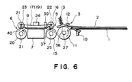
- Figs. 6 and 7 show an example of a conventional automatic sheet supplying apparatus of the above-mentioned type.
- the reference numeral 1 denotes an original support on which original sheets 2 are stacked; 3 denotes a sheet separating means disposed at a downstream side of the original support 1; 5 denotes a sheet supply means disposed at a downstream side of the sheet separating means 3; 6 denotes a sheet ejecting means disposed at a downstream side of the sheet supply means 5; and 7 denotes an image sensor of contact type disposed below an upper original guide plate 9 between the sheet supply means 5 and the sheet ejecting means 6.
- An original presence/absence detection sensor 10 for detecting the presence or absence of the original sheet 2 stacked on the original support 1 is provided in connection with the original support 1.
- the sheet separating means 3 is constituted by a separation roller 11 and a friction plate (friction member) 12 urged against the separation roller 11 with a predetermined pressure.
- the friction plate 12 is biased by a separating and urging spring (coil spring) 13 toward the separation roller.
- the sheet supply means 5 is constituted by a sheet supply roller 15 and a driven roller 16 urged against the sheet supply roller 15 with a predetermined pressure.
- the driven roller 16 is biased by a plurality of leaf springs 17, 19 toward the sheet supply roller.
- the sheet ejecting means 6 is constituted by an ejector roller 20 and a driven roller 21 urged against the ejector roller 20 with a predetermined pressure.
- the driven roller 21 is biased by a plurality of leaf springs 17, 19 toward the ejector roller.
- the ejector roller 20 and the driven roller 21 of the sheet ejecting means 6 are made of material same as those of the sheet supply roller 15 and the driven roller 16 of the sheet supply means 5, respectively.
- the leaf springs 17, 19 extend between and are rested on shafts 22, 23 of the driven rollers 16, 21 so that they apply the same pressure to the roller shafts 22, 23 by a weight 24 disposed at central portions of the leaf springs.
- a rotational force from a motor (not shown) is transmitted to the separation roller 11 of the sheet separating means 3, the sheet supply roller 15 of the sheet supply means 5 and the ejector roller 20 of the sheet ejecting means 6.
- the rotational force of the motor is firstly transmitted to the sheet supply roller 15, and the rotational force transmitted to the sheet supply roller 15 is transmitted to the separation roller 11 and the ejector roller 20.
- a gear 26 for transmitting the rotational force of the motor is attached to one end of a roller shaft 25 of the sheet supply roller 15.
- a gear 30 connected to the gear 26 through an intermediate gear 29 is attached to one end of a roller shaft 27 of the separation roller 11.
- pulleys 32, 33 having the same diameters are attached to one end of the roller shaft 25 of the sheet supply roller 15 and one end of a roller shaft 31 of the ejector roller 20, these pulleys being interconnected by an endless belt 35.
- the rotational force transmitted to the sheet supply roller 15 is transmitted to the separation roller 11 via the gear 26, intermediate gear 29 and gear 30, and, at the same time, is transmitted to the ejector roller 20 via the belt 35.
- the motor is drivingly rotated when the original presence/absence sensor 10 detects the original sheet 2 stacked on the original support 1.
- the sheet separating means 3 since the relation between a friction force ⁇ 1 (between the separation roller 11 and the original sheet 2) and a friction force ⁇ 2 (between the friction plate 12 and the original sheet 2) and a friction force ⁇ 3 (between the original sheets 2) is so selected as to be ⁇ 1 > ⁇ 2 > ⁇ 3 , a plurality of originals 2 can be separated in a nip between the separation roller 11 and the friction plate 12 so that only the lowermost original sheet is separated by the separation roller 11 and is fed.
- the original sheet When the leading end of the original sheet is pinched by a nip 40 between the ejector roller 20 and the driven roller 21, the original sheet is conveyed without any slack by means of the ejector roller 20 and the sheet supply roller 15 which are rotated at the same speed.
- the original sheet When a trailing end of the original sheet 2 has passed through the nip 37 between the sheet supply roller 15 and the driven roller 16 and is detected by the original end detection sensor 39, the original sheet is conveyed by the ejector roller 20 by a predetermined amount.
- the above-mentioned conventional automatic sheet supplying apparatus is so designed that, immediately after the trailing end of the firstly fed original sheet 2 has passed through the nip 36 between the separation roller 11 and the friction plate 12, a next original sheet 2 rested on the original support 1 is supplied with following the firstly fed original sheet 2.
- the original end detection sensor 39 cannot correctly detect the trailing end of the firstly fed original sheet 2 and the leading end of the next original sheet 2, with the result that the image information cannot be correctly read by the image sensor 7 and/or the original sheet cannot be correctly ejected.
- the conventional automatic sheet supplying apparatus is so designed that there is a difference in sheet feeding speed between the previous original sheet 2 and the next original sheet 2 by setting a peripheral speed of the sheet supply roller 15 to be faster than that of the separation roller 11. In this way, since the previous original sheet is conveyed by the faster sheet supply roller 15 and the next original sheet 2 is conveyed by the slower separation roller 11, a gap is created between the trailing end of the previous original sheet 2 and the leading end of the next original sheet 2.
- a one-way clutch 41 of needle type is provided on the gear 30 attached to the roller shaft 27 of the separation roller 11 so that, when the original sheet 2 is fed at a speed greater than the peripheral speed of the separation roller 11, the peripheral speed of the separation roller 11 becomes the same as the speed of the original sheet 2.
- the one-way clutch 41 of needle type is very expensive, and does not permit to reduce a pitch circle of the gear 30 due to the outer configuration of the clutch, and, accordingly, the roller shaft 27 is lengthened, thus limiting the applications of the apparatus.
- the one-way clutch when used, if outer diameters of the separation roller 11 and the sheet supply roller 15 are preselected, the numbers of teeth of the gears associated with the separation roller 11 and the sheet supply roller 15 must be altered in order to control the gap between the previous original sheet 2 and the next original sheet 2, which is very difficult in design.
- a spring clutch In place of the one-way clutch of needle type, a spring clutch can be used.
- the spring clutch has a disadvantage that it generates the noise and/or slip if an amount of grease applied to the clutch is not proper, the control of the spring clutch is very troublesome.
- the US-A-3 184 231 shows a sheet feeding mechanism for a facsimile transmitter having a feed roller for separating the sheets and feeding the sheets into a copy feeding system.
- the rotational speed of the feed roller is selected somewhat slower with respect to the speed of the copy feeding system to create a space between the individual sheets.
- the feed roller is driven by a one-way clutch having a ratchet and a spring-urged pawl.
- the present invention aims to solve the above-mentioned conventional problems, and an object of the present invention is to provide an automatic sheet supplying apparatus which does not use any parts such as a one-way clutch that causes various problems in view of cost, design, application and control, and which does not detriorate image information recorded on a sheet and can create a proper gap between a trailing end of a previous sheet and a leading end of a next sheet.
- the present invention provides an automatic sheet supplying apparatus according to claim 1
- such an apparatus may comprise a sheet separating means (3) constituted by a separation roller (11) and a friction member (12) urged against the separation roller (11) with a predetermined pressure, and a sheet supply means (5) constituted by a sheet supply roller (15) and a driven roller (16) urged against the sheet supply roller (15) with a predetermined pressure, whereby sheets (2) are separated one by one by means of the sheet separating means (3) and the separated sheet (2) is supplied by the sheet supply means (5).
- a sheet separating means (3) constituted by a separation roller (11) and a friction member (12) urged against the separation roller (11) with a predetermined pressure
- a sheet supply means (5) constituted by a sheet supply roller (15) and a driven roller (16) urged against the sheet supply roller (15) with a predetermined pressure
- a rotational force is discontinuously or intermittently transmitted to the separation roller (11) of the sheet separating means (3) and is continuously transmitted to the sheet supply roller (15) of the sheet supply means (5). Further, the rotational force is transmitted to the separation roller (11) of the sheet separating means (3) via an intermittent gear (42) meshed with a gear (30) on a roller shaft (27). Further, the rotational force can be transmitted to the separation roller (11) of the sheet separating means (3) by abutting one of protruded portions (4b1, 4b2) of an intermittent cam (4) rotated in synchronous with a roller shaft (25) against the separation roller.
- the rotational force can be transmitted to the separation roller (11) intermittently.
- the rotational force is transmitted to the separation roller (11) when a toothed portion of the intermittent gear (42) is meshed with the gear (30) attached to the roller shaft (27) and is not transmitted to the separation roller when the toothed portion of the intermittent gear (42) is disengaged from the gear (30).
- the automatic sheet supplying apparatus is so designed that the rotational force is transmitted to the separation roller of the sheet separating means intermittently and to the sheet supply roller of the sheet supply means continuously, it is possible to create a gap between the trailing end of the previous sheet and the leading end of the next sheet. Accordingly, it is possible to surely detect the trailing end of the previous sheet and the leading end of the next sheet.
- the sheet supply roller may also be rotated intermittently. However, in this case, a stop time period of the sheet supply roller should be shorter than that of the separation roller. Accordingly, an arrangement wherein the sheet supply roller is rotated with a fine intermittent movement by means of a stepping motor and the like is included in the scope of the present invention.
- the separation roller when the sheet is fed by both the sheet supply roller and the separation roller, if the rotational force is not transmitted to the separation roller, the latter is rotated at the same peripheral speed as that of the sheet supply roller due to the friction force between the separation roller and the sheet being pulled by the sheet supply roller.
- the image information recorded by a pencil and the like on the sheet is not damaged or detriorated by the relative slip between the sheet and the separation roller.
- the means for intermittently transmitting the rotational force to the separation roller comprises the intermittent gear meshed with the gear attached to the roller shaft of the separation roller or intermittent cam driving the separation roller by intermittently abutting against the latter, there are no problems which were arisen by the one-way clutch, in view of cost, design, application and control.
- Figs. 1 and 2 show an automatic sheet supplying apparatus according to the present invention incorporated into a facsimile.
- the same parts as those in the aforementioned conventional apparatus Figs. 6 and 7) are designated by the same reference numerals and the explanation thereof will be omitted.
- a rotational force from a motor 43 is continuously transmitted to a sheet supply roller 15 of the automatic sheet supplying apparatus, via a gear 46 attached to a motor shaft 45, idle gears 47, 49 and gear 26 attached to a roller shaft 25.
- the rotational force transmitted to the sheet supply roller 15 is discontinuously (intermittently) transmitted to a separation roller 11 of the automatic sheet supplying apparatus, via the gear 26 attached to the roller shaft 25, intermediate gear 29, intermittent gear 42 integrally formed with the intermediate gear 29, and gear 30 attached to a roller shaft 27. Accordingly, when the motor 43 is rotated, the sheet supply roller 15 (and an ejector roller 20) is rotated continuously. Whereas, when a toothed portion of the intermittent gear 42 is engaged by the gear 30, the separation roller 11 is rotated, and, when the toothed portion is disengaged from the gear 30, the separation roller 11 is stopped.
- the separation roller 11 and the sheet supply roller 15 rotated as mentioned above are so designed that a peripheral speed of the former becomes the same as that of the latter to feed an original sheet 2 at a constant speed. Accordingly, even when the original sheet is fed by both rollers 11, 15 simultaneously, there is no slip between the original sheet and the rollers.
- the automatic sheet supplying apparatus having the above-mentioned arrangement, when the original sheets 2 stacked on an original support 1 are separated one by one by means of the separation roller 11 and the separated original sheet 2 is conveyed by the separation roller 11 up to a position ahead of a nip 37 between the sheet supply roller 15 and a driven roller 16, since the separation roller 11 is rotated discontinuously, the original sheet 2 is also conveyed discontinuously (intermittently). That is to say, while the toothed portion of the intermittent gear 42 is being engaged by the gear 30, the original sheet 2 is shifted, whereas, when the toothed portion is disengaged from the gear 30, the original sheet is stopped.
- the number of teeth of the gear is Z30
- the number of actual teeth of the intermittent gear 42 is ZX
- the number of phantom teeth corresponding to a non-toothed portion of the intermittent gear 42 is ZY
- the separation roller 11 repeats an operation for feeding the original sheet 2 by a distance ⁇ D(ZX)/Z30 and a stoppage for a distance ⁇ D(ZY)/Z30.
- the original sheet 2 is conveyed by both the sheet supply roller 15 and the separation roller 11.
- the sheet supply roller 15 is rotated continuously and the separation roller 11 is rotated intermittently, the original sheet 2 is conveyed by both the sheet supply roller 15 and the separation roller 11 which are rotated at the same peripheral speeds if the separation roller 11 is in the rotatable condition (i.e., if the toothed portion of the intermittent gear 42 is engaged by the gear 30).
- the separation roller 11 is in the non-rotatable condition (i.e., if the toothed portion of the intermittent gear 42 is disengaged from the gear 30), the original sheets 2 is conveyed only by the sheet supply roller 15. In this case, since the original sheet 2 is pulled by the sheet supply roller 15, the separation roller 11 continues to be rotated at the same peripheral speed as that of the sheet supply roller 15 by an original sheet conveying force. Thus, when the rotational force is not transmitted to the separation roller 11, the latter is rotated as if continuously.
- next original sheet 2 At the time when the next original sheet 2 starts to be fed by the separation roller 11, it is shifted with being continuous to the previous original sheet (i.e., in a condition that there is no gap (clearance) between the leading end of the next original sheet and the trailing end of the previous original sheet). This condition continues until the toothed portion of the intermittent gear 42 is disengaged from the gear 30 to stop the separation roller 11 temporarily. When the separation roller 11 is stopped (non-rotatable condition), the next original sheet 2 is also stopped temporarily. When the toothed portion of the intermittent gear 42 is engaged by the gear 30 again, the next original sheet 2 is conveyed again by the separation roller 11. Meanwhile, the previous original sheet 2 is being fed continuously by the sheet supply roller 15.
- a distance between the trailing end of the previous original sheet 2 and the leading nd of the next original sheet 2 becomes ⁇ D(ZY)/Z30, thus surely creating the gap between the trailing end of the previous original sheet 2 and the leading end of the next original sheet 2.
- an original end detection sensor 39 can surely detect the gap between the trailing end of the previous original sheet 2 and the leading end of the next original sheet 2.
- the previous original sheet 2 When the leading end of the previous original sheet 2 enters into a nip 40 between the ejector roller 20 and a driven roller 21, the previous original sheet 2 is conveyed by both the ejector roller 20 and the sheet supply roller 15 which are rotated at the same peripheral speed.
- the trailing end of the previous original sheet 2 has passed through the nip 37 between the sheet supply roller 15 and the driven roller 16, the previous original sheet 2 is conveyed only by the ejector roller 20. Meanwhile, the above-mentioned distance ( ⁇ D(ZY)/Z30) is maintained.
- the next original sheet 2 is fed in the same manner as the previous original sheet 2.
- the distance between the trailing end of the previous original sheet 2 and the leading end of the next original sheet 2 must have a certain minimum value to be surely detected by the original end detection sensor 39.
- this minimum value is L 2
- a relation L 2 ⁇ ⁇ D(ZY)/Z30 may be satisfied.
- an outer diameter of the sheet supply roller 15 is 12 mm
- an outer diameter of the separation roller 11 is 20 mm
- L 1 is 20 mm
- L 2 is 6 mm
- the number of teeth of the gear 30 is 40
- module of the gear 30 is 0.5
- the number of teeth of the gear 26 is 24
- module of the gear 26 is 0.5
- the above requirements are satisfied by using the intermittent gear 42 having the number of teeth of 16 (with toothed portion having the number of teeth of 10) and module of 0.5.
- the rotational force is intermittently transmitted to the separation roller 11, and this is realized by using the intermittent gear 42 meshed with the gear 30.
- the intermittent gear 42 does not arise the problems caused by the one-way clutch in view of cost, application and control, and is useful practically.
- the intermittent gear 42 when the distance L 2 is controlled, the numbers of teeth of the gears 26, 30 do not need to be varied or changed, and, thus, it is possible to control the distance L 2 only by changing the numbers of teeth of the intermittent gear 42 and the intermediate gear 29 (these gears being formed integrally with each other).
- the gear 26 is fixedly mounted on one end of the roller shaft 25 of the sheet supply roller 15, and a rotational force is transmitted from a gear 49 connected to the motor 43 (Fig. 1) to the gear 26.
- the gear 26 is meshed with the intermediate gear 29 integrally formed with a support shaft 29a to which an intermittent cam 4 is fixed.
- the intermittent cam 4 is made of an elastic member such as hard rubber and is provided at its peripheral surface with recesses 4a and protruded portions 4b.
- the recesses 4a and the protruded portions 4b may comprise a pair of recesses 4al, 4a2 diametrically opposed to each other and a pair of protruded portions 4b1, 4b2 diametrically opposed to each other, respectively, as shown in Fig. 4.
- the separation roller 11 comprises a metal core 11b and a soft layer 11a made of soft rubber and covering the metal core.
- the protruded portion 4b1 (4b2) of the intermittent cam 4 can interfare with the soft layer 11a of the separation roller 11 so that the protruded portion penetrates into the soft layer 11a to provide a penetrated portion 11c as shown.
- the sheet supply roller 15 is continuously rotated by the rotational force of the motor 43 in a direction shown by the arrow in Fig. 4 through the gear 49. Further, the rotational force of the motor 43 is transmitted to the intermittent cam 4 via the intermediate gear 29 meshed with the gear 26, thereby rotating the intermittent cam 4 in a direction shown by the arrow.
- the protruded portion 4b1 (or 4b2) of the intermittent cam 4 penetrates into the soft layer 11a of the separation roller 11 as shown in Fig. 4, the rotational force of the intermittent cam is transmitted to the separation roller 11 to rotate the latter in the direction shown by the arrow.
- the recess 4a1 (or 4a2) is opposed to the separation roller 11, the latter is in the non-rotatable condition.
- the separation roller 11 is discontinuously rotated in the direction shown by the arrow by means of the protruded portion 4b1 or 4b2 of the intermittent cam 4 to feed the separated original sheet 2 toward the sheet supply roller 15 (positioned at a downstream side of the separation roller) intermittently.
- the original sheet 2 enters into the nip 37 between the sheet supply roller 15 and the driven roller 16, it is fed by both the sheet supply roller 15 and the separation roller 11.
- the recess 4a1 or 4a2 of the intermittent cam 4 opposes to the separation roller 11 to bring the latter to the non-rotatable condition, the original sheet 2 is fed only by the sheet supply roller 15, with the result that the separation roller 11 is rotatingly driven by the movement of the original sheet 2.
- the peripheral speed of the separation roller 11 (being rotated) can be the same as that of the sheet supply roller 15, when the original sheet 2 is fed by both the sheet supply roller 15 and the separation roller 11, the image information recorded by the pencil and the like on the original sheet 2 is not detriorated due to the relative slip between the original sheet and the separation roller 11. Since the previous original sheet 2 is fed continuously and the next original sheet 2 (immediately after separated) is fed discontinuously, the gap (clearance) is surely created between the trailing end of the previous original sheet 2 and the leading end of the next original sheet 2. Consequently, the trailing end of the previous original sheet 2 and the leading end of the next original sheet 2 can be surely detected by the original end detection sensor 39.
- peripheral speeds of the sheet supply roller 15 and of the separation roller 11 are normally selected to be the same, these speeds may be differentiated.
- the peripheral speed of the separation roller 11 may be faster than that of the sheet supply roller 15.
- the intermittent cam 4 can be made of other materials such as synthetic resin, than the hard rubber.
- peripheral surfaces of the protruded portions 4b1, 4b2 of the intermittent cam 4 may be knurled to improve the transmission ability of the rotational force to the separation roller 11.
Landscapes
- Engineering & Computer Science (AREA)
- Multimedia (AREA)
- Signal Processing (AREA)
- Mechanical Engineering (AREA)
- Sheets, Magazines, And Separation Thereof (AREA)
- Delivering By Means Of Belts And Rollers (AREA)
- Facsimiles In General (AREA)
- Handling Of Cut Paper (AREA)
- Controlling Sheets Or Webs (AREA)
Claims (15)
- Automatisches Blattzufuhrgerät mit:einem ersten Zufuhrdrehbauteil (11, 12) zum aussetzenden Zuführen eines Blattes (2); undeinem zweiten Zufuhrdrehbauteil (15, 16), das gegenüber dem ersten Zufuhrdrehbauteil (11, 12) in der Blattzufuhrrichtung stromabseitig angeordnet und geeignet ist, das Blatt (2) um eine Drehzeitperiode länger als die des ersten Zufuhrdrehbauteils (11, 12) zuzuführen,wodurch ein Abstand zwischen einem vorausgehenden zugeführten Blatt (2) und einem nächsten Blatt erzeugt wird.
- Automatisches Blattzufuhrgerät gemäß Anspruch 1, dadurch gekennzeichnet, daß die Drehbewegung des zweiten Zufuhrdrehbauteils (15, 16) kontinuierlich ist, wobei es weiterhin eine Einrichtung (49) zum kontinuierlichen Drehen des zweiten Zufuhrdrehbauteils (15, 16) hat.
- Automatisches Blattzufuhrgerät gemäß Anspruch 1, mit weiterhin einem Blattstapelträger (1) auf dem die Blätter (2) gestapelt sind, wobei das erste Zufuhrdrehbauteil (11, 12) eine Zufuhreinrichtung zum Trennen und Zuführen von den auf dem Blattstapelträger (1) gestapelten Blättern (2) eines nach dem anderen hat.
- Automatisches Blattzufuhrgerät gemäß Anspruch 1, dadurch gekennzeichnet, daß das erste Zufuhrdrehbauteil (11, 12) ein Antriebszahnrad (30) hat, wobei eine Drehkraft über ein in Kämmeingriff mit dem Antriebszahnrad (30) befindliches aussetzendes Zahnrad (42) zum ersten Zufuhrdrehbauteil (11, 12) übertragen wird.
- Automatisches Blattzufuhrgerät gemäß Anspruch 1, dadurch gekennzeichnet, daß das erste Zufuhrdrehbauteil (11, 12) ein Reibbauteil (11a) hat, wobei eine Drehkraft über ein Reibdrehbauteil (4b; 4b1; 4b2), das aussetzend gegen das Reibbauteil stößt, zum ersten Zufuhrdrehbauteil (11, 12) übertragen wird.
- Automatisches Blattzufuhrgerät gemäß Anspruch 3, dadurch gekennzeichnet, daß die Zufuhreinrichtung eine Trennrolle (11) zum Zuführen des auf dem Blattstapelträger (1) befindlichen untersten Blatts (2) und ein Reibbauteil (12) hat, das gegen die Trennrolle (11) gedrückt wird, wobei das zweite Zufuhrdrehbauteil (15, 16) eine untere Förderrolle (15) und eine obere Rolle (16) hat, die gegen die Förderrolle (15) gedrückt wird.
- Automatisches Blattzufuhrgerät gemäß Anspruch 2, mit weiterhin:einem kontinuierlich drehenden Motor (43);einer ersten Übertragungseinrichtung (46, 47, 49, 26, 42, 30; 29), um die Drehkraft des Motors (43) zum ersten Zufuhrdrehbauteil (11, 12) aussetzend zu übertragen; undeiner zweiten Übertragungseinrichtung (46, 47, 49, 26) zum kontinuierlichen Übertragen der Drehkraft des Motors (43) zum zweiten Zufuhrdrehbauteil (15, 16).
- Automatisches Blattzufuhrgerät gemäß Anspruch 7, dadurch gekennzeichnet, daß die erste (46, 47, 49, 26, 42, 30; 29) und die zweite (46, 47, 49, 26) Übertragungseinrichtung derart konstruiert ist, daß die Umfangsgeschwindigkeit des ersten Zufuhrdrehbauteils (11, 12) gleich der des zweiten Drehbauteils (15, 16) wird, wobei das erste Zufuhrdrehbauteil (11, 12) durch die Bewegung des Blattes (2) drehend angetrieben wird, wenn das Blatt (2) durch das zweite Zufuhrdrehbauteil (15, 16) zugeführt wird.
- Automatisches Blattzufuhrgerät gemäß Anspruch 7 oder 8, dadurch gekennzeichnet, daß die erste Übertragungseinrichtung (46, 47, 49, 26, 29, 30) einen Getriebezug mit einem aussetzenden Zahnrad (29) hat.
- Automatisches Blattzufuhrgerät gemäß Anspruch 5, dadurch gekennzeichnet, daß das Reibbauteil (11a) ein Reibrad ist, um die Drehkraft zum ersten Zufuhrdrehbauteil (11) aussetzend zu übertragen.
- Automatisches Blattzufuhrgerät gemäß einem der vorstehenden Ansprüche 1 bis 10, dadurch gekennzeichnet, daß das Blatt eine Original ist.
- Gerät gemäß Anspruch 12, mit weiterhin:einer Leseeinrichtung, die stromabseitig des zweiten Zufuhrdrehbauteils (15, 16) in Zuführrichung des Originals angeordnet und geeignet ist, das Original zu lesen;wodurch die Originale durch Erzeugen eines Abstands zwischen dem vorausgehend zugeführten Original und einem nächsten Original eines nach dem anderen gelesen werden.
- Gerät gemäß Anspruch 12, dadurch gekennzeichnet, daß stromabseitig der Leseeinrichtung (7) ein weiteres Förderdrehbauteil (20, 21) angeordnet ist, wobei das zweite Zufuhrdrehbauteil (15, 16) und das zusätzliche Förderdrehbauteil (20, 21) durch eine gemeinsame Antriebsquelle angetrieben werden.
- Gerät gemäß Anspruch 12, mit weiterhin einem Sensor (39) zum Erfassen des Originals, das zwischen dem zweiten Zufuhrdrehbauteil (15, 16) und der Leseeinrichtung (7) angeordnet ist.
- Automatisches Blattzufuhrgerät gemäß Anspruch 1, dadurch gekennzeichnet, daß die Drehbewegung des zweiten Zufuhrdrehbauteils (15, 16) aussetzend ist, wobei ihre Anhaltezeitperiode kürzer als die des ersten Zufuhrdrehbauteils (11, 12) ist.
Applications Claiming Priority (4)
| Application Number | Priority Date | Filing Date | Title |
|---|---|---|---|
| JP195279/90 | 1990-07-24 | ||
| JP19527990 | 1990-07-24 | ||
| JP154081/90 | 1991-05-29 | ||
| JP3154081A JPH04313528A (ja) | 1990-07-24 | 1991-05-29 | 自動給紙装置 |
Publications (3)
| Publication Number | Publication Date |
|---|---|
| EP0468432A2 EP0468432A2 (de) | 1992-01-29 |
| EP0468432A3 EP0468432A3 (en) | 1992-10-21 |
| EP0468432B1 true EP0468432B1 (de) | 1997-12-17 |
Family
ID=26482499
Family Applications (1)
| Application Number | Title | Priority Date | Filing Date |
|---|---|---|---|
| EP91112309A Expired - Lifetime EP0468432B1 (de) | 1990-07-24 | 1991-07-23 | Automatisches Blattzufuhrgerät |
Country Status (5)
| Country | Link |
|---|---|
| US (1) | US5222723A (de) |
| EP (1) | EP0468432B1 (de) |
| JP (1) | JPH04313528A (de) |
| DE (1) | DE69128441T2 (de) |
| ES (1) | ES2111546T3 (de) |
Families Citing this family (8)
| Publication number | Priority date | Publication date | Assignee | Title |
|---|---|---|---|---|
| JP2992941B2 (ja) * | 1992-06-16 | 1999-12-20 | 三田工業株式会社 | 自動原稿搬送装置 |
| US5423526A (en) * | 1992-06-26 | 1995-06-13 | Canon Kabushiki Kaisha | Sheet supplying apparatus |
| TW344781B (en) * | 1996-02-09 | 1998-11-11 | Murada Kikai Kk | Drive transmission mechanism |
| US5791646A (en) * | 1996-08-19 | 1998-08-11 | Behavior Tech Computer Corp. | Automatic document feeder |
| US7431284B2 (en) * | 2001-06-13 | 2008-10-07 | Hewlett-Packard Development Company, L.P. | Sheet transfer apparatus |
| US7654513B2 (en) * | 2008-03-20 | 2010-02-02 | Lexmark International, Inc. | Feed assist assembly |
| JP2013139336A (ja) * | 2011-12-05 | 2013-07-18 | Canon Inc | シート給送装置及び画像形成装置 |
| JP2022029272A (ja) * | 2020-08-04 | 2022-02-17 | キヤノン株式会社 | シート搬送装置 |
Family Cites Families (11)
| Publication number | Priority date | Publication date | Assignee | Title |
|---|---|---|---|---|
| US3184231A (en) * | 1962-05-31 | 1965-05-18 | Hogan Faximile Corp | Facsimile transmitter sheet feeding mechanism |
| JPS5211997B2 (de) * | 1973-05-10 | 1977-04-04 | ||
| HU181330B (en) * | 1981-05-18 | 1983-07-28 | Irodagepipari Es Finomechanika | Sheet feeding device particularly for electrophotographic duplicator |
| JPS5839164A (ja) * | 1981-09-02 | 1983-03-07 | Nec Corp | フアクシミリ送信装置 |
| US4600929A (en) * | 1984-06-01 | 1986-07-15 | At&T Teletype Corporation | Apparatus for handling paper in a printer |
| KR890000910B1 (ko) * | 1984-06-29 | 1989-04-13 | 가부시기가이샤 히다찌세이사꾸쇼 | 지엽류의 분리 반송장치 |
| JPS61174085A (ja) * | 1985-01-28 | 1986-08-05 | 株式会社日立製作所 | エレベ−タの戸の案内装置 |
| JPS62244828A (ja) * | 1986-04-16 | 1987-10-26 | Sanyo Electric Co Ltd | 給紙装置 |
| DE3750866T2 (de) * | 1986-09-11 | 1995-05-24 | Canon Kk | Bildaufzeichnungsverfahren. |
| JP2521303B2 (ja) * | 1987-09-07 | 1996-08-07 | シャープ株式会社 | 自動給紙装置 |
| JPH02152846A (ja) * | 1988-12-01 | 1990-06-12 | Sharp Corp | 給紙制御装置 |
-
1991
- 1991-05-29 JP JP3154081A patent/JPH04313528A/ja active Pending
- 1991-07-22 US US07/733,839 patent/US5222723A/en not_active Expired - Lifetime
- 1991-07-23 DE DE69128441T patent/DE69128441T2/de not_active Expired - Fee Related
- 1991-07-23 ES ES91112309T patent/ES2111546T3/es not_active Expired - Lifetime
- 1991-07-23 EP EP91112309A patent/EP0468432B1/de not_active Expired - Lifetime
Also Published As
| Publication number | Publication date |
|---|---|
| US5222723A (en) | 1993-06-29 |
| EP0468432A3 (en) | 1992-10-21 |
| DE69128441D1 (de) | 1998-01-29 |
| ES2111546T3 (es) | 1998-03-16 |
| JPH04313528A (ja) | 1992-11-05 |
| EP0468432A2 (de) | 1992-01-29 |
| DE69128441T2 (de) | 1998-05-14 |
Similar Documents
| Publication | Publication Date | Title |
|---|---|---|
| US4934686A (en) | Sheet feeding apparatus with a constant friction torque generating mechanism | |
| US4927130A (en) | Automatic sheet feeder | |
| US6095515A (en) | Sheet supplying apparatus with separating means and guide | |
| EP0468432B1 (de) | Automatisches Blattzufuhrgerät | |
| EP0576035B1 (de) | Blattzuführvorrichtung | |
| US5886729A (en) | Sheet supplying apparatus using a flexible elastic pawl member for separating sheets one by one | |
| US6135439A (en) | Sheet feeding apparatus | |
| US5362037A (en) | Method of, and apparatus for, delivering flat articles one by one from a stack of such articles | |
| KR100516147B1 (ko) | 자동 분리 및 공급장치 | |
| US5884135A (en) | Limited rotation slip clutch | |
| US6332608B1 (en) | Sheet feeding apparatus | |
| CN100547493C (zh) | 片材供给装置 | |
| JPS5912029A (ja) | 用紙の重送検出及び防止装置 | |
| US5357325A (en) | Image forming apparatus having transfer member rotating faster than image bearing member | |
| EP0657296A1 (de) | Papierzuführvorrichtung | |
| US6840168B2 (en) | Paper sheet stamp apparatus | |
| CN1098166C (zh) | 印制设备用的自动进纸装置 | |
| JP2000085999A (ja) | シート供給装置と該装置を備えた画像形成装置 | |
| JP2758524B2 (ja) | 自動給紙装置 | |
| JPH04371426A (ja) | 給紙装置 | |
| US6443446B1 (en) | Media transport mechanism for information transfer devices | |
| JPS6127838A (ja) | 原稿給紙装置 | |
| JPH04313548A (ja) | シート搬送装置 | |
| KR100258324B1 (ko) | 팩시밀리의 열전사리본 마찰 동력전달장치 | |
| JP3446975B2 (ja) | 給紙装置 |
Legal Events
| Date | Code | Title | Description |
|---|---|---|---|
| PUAI | Public reference made under article 153(3) epc to a published international application that has entered the european phase |
Free format text: ORIGINAL CODE: 0009012 |
|
| AK | Designated contracting states |
Kind code of ref document: A2 Designated state(s): DE ES FR GB IT |
|
| PUAL | Search report despatched |
Free format text: ORIGINAL CODE: 0009013 |
|
| AK | Designated contracting states |
Kind code of ref document: A3 Designated state(s): DE ES FR GB IT |
|
| 17P | Request for examination filed |
Effective date: 19930308 |
|
| 17Q | First examination report despatched |
Effective date: 19950714 |
|
| GRAG | Despatch of communication of intention to grant |
Free format text: ORIGINAL CODE: EPIDOS AGRA |
|
| GRAG | Despatch of communication of intention to grant |
Free format text: ORIGINAL CODE: EPIDOS AGRA |
|
| GRAG | Despatch of communication of intention to grant |
Free format text: ORIGINAL CODE: EPIDOS AGRA |
|
| GRAH | Despatch of communication of intention to grant a patent |
Free format text: ORIGINAL CODE: EPIDOS IGRA |
|
| GRAH | Despatch of communication of intention to grant a patent |
Free format text: ORIGINAL CODE: EPIDOS IGRA |
|
| GRAA | (expected) grant |
Free format text: ORIGINAL CODE: 0009210 |
|
| AK | Designated contracting states |
Kind code of ref document: B1 Designated state(s): DE ES FR GB IT |
|
| REF | Corresponds to: |
Ref document number: 69128441 Country of ref document: DE Date of ref document: 19980129 |
|
| ITF | It: translation for a ep patent filed | ||
| REG | Reference to a national code |
Ref country code: ES Ref legal event code: FG2A Ref document number: 2111546 Country of ref document: ES Kind code of ref document: T3 |
|
| ET | Fr: translation filed | ||
| PLBE | No opposition filed within time limit |
Free format text: ORIGINAL CODE: 0009261 |
|
| STAA | Information on the status of an ep patent application or granted ep patent |
Free format text: STATUS: NO OPPOSITION FILED WITHIN TIME LIMIT |
|
| 26N | No opposition filed | ||
| REG | Reference to a national code |
Ref country code: GB Ref legal event code: IF02 |
|
| PGFP | Annual fee paid to national office [announced via postgrant information from national office to epo] |
Ref country code: ES Payment date: 20080604 Year of fee payment: 18 |
|
| PGFP | Annual fee paid to national office [announced via postgrant information from national office to epo] |
Ref country code: DE Payment date: 20080731 Year of fee payment: 18 |
|
| PGFP | Annual fee paid to national office [announced via postgrant information from national office to epo] |
Ref country code: FR Payment date: 20080722 Year of fee payment: 18 Ref country code: IT Payment date: 20080722 Year of fee payment: 18 |
|
| PGFP | Annual fee paid to national office [announced via postgrant information from national office to epo] |
Ref country code: GB Payment date: 20080722 Year of fee payment: 18 |
|
| GBPC | Gb: european patent ceased through non-payment of renewal fee |
Effective date: 20090723 |
|
| REG | Reference to a national code |
Ref country code: FR Ref legal event code: ST Effective date: 20100331 |
|
| PG25 | Lapsed in a contracting state [announced via postgrant information from national office to epo] |
Ref country code: FR Free format text: LAPSE BECAUSE OF NON-PAYMENT OF DUE FEES Effective date: 20090731 |
|
| PG25 | Lapsed in a contracting state [announced via postgrant information from national office to epo] |
Ref country code: GB Free format text: LAPSE BECAUSE OF NON-PAYMENT OF DUE FEES Effective date: 20090723 |
|
| PG25 | Lapsed in a contracting state [announced via postgrant information from national office to epo] |
Ref country code: DE Free format text: LAPSE BECAUSE OF NON-PAYMENT OF DUE FEES Effective date: 20100202 |
|
| REG | Reference to a national code |
Ref country code: ES Ref legal event code: FD2A Effective date: 20090724 |
|
| PG25 | Lapsed in a contracting state [announced via postgrant information from national office to epo] |
Ref country code: ES Free format text: LAPSE BECAUSE OF NON-PAYMENT OF DUE FEES Effective date: 20090724 |
|
| PG25 | Lapsed in a contracting state [announced via postgrant information from national office to epo] |
Ref country code: IT Free format text: LAPSE BECAUSE OF NON-PAYMENT OF DUE FEES Effective date: 20090723 |