EP0468454A2 - Unterbrechungssteuerung - Google Patents
Unterbrechungssteuerung Download PDFInfo
- Publication number
- EP0468454A2 EP0468454A2 EP91112339A EP91112339A EP0468454A2 EP 0468454 A2 EP0468454 A2 EP 0468454A2 EP 91112339 A EP91112339 A EP 91112339A EP 91112339 A EP91112339 A EP 91112339A EP 0468454 A2 EP0468454 A2 EP 0468454A2
- Authority
- EP
- European Patent Office
- Prior art keywords
- interrupt
- interrupt request
- register
- controller
- generation
- Prior art date
- Legal status (The legal status is an assumption and is not a legal conclusion. Google has not performed a legal analysis and makes no representation as to the accuracy of the status listed.)
- Granted
Links
Images


Classifications
-
- G—PHYSICS
- G06—COMPUTING OR CALCULATING; COUNTING
- G06F—ELECTRIC DIGITAL DATA PROCESSING
- G06F13/00—Interconnection of, or transfer of information or other signals between, memories, input/output devices or central processing units
- G06F13/14—Handling requests for interconnection or transfer
- G06F13/20—Handling requests for interconnection or transfer for access to input/output bus
- G06F13/24—Handling requests for interconnection or transfer for access to input/output bus using interrupt
Definitions
- the present invention relates to the configuration of an interrupt controller which requests an interrupt processing to a processor when an external device occurs leading or trailing edge in an interrupt request signal of the interrupt controller.
- an interrupt request from an external device to a processor is assigned to the processor through an interrupt controller.
- the interrupt request from the external device is assigned to the interrupt controller in the form of an edge trigger or a level trigger on an interrupt request signal.
- an edge trigger the interrupt is requested when the interrupt signal is changed from a high level to a low level or from a low level to a high level.
- a level trigger the interrupt is requested from a low level state or from a high level state of an interrupt request signal. The selection as to which of these triggers is used is made by the interrupt controller.
- the interrupt controller recognizes the generation of an interrupt request from an external device, and enters the interrupt generation state.
- the interrupt request signal to the processor is then validated and the interrupt processing is requested from the controller.
- the interrupt controller when the processor responds to the interrupt request from the controller, the interrupt controller is released from the interrupt generation state by an interrupt acknowledge signal which is asserted by a processor during that interrupt acknowledge cycle. Or alternately, the interrupt controller is released from the interrupt generation state by the program during the interrupt processing corresponding to that interrupt request. The interrupt controller, on being released from the interrupt generation state, enters an interrupt non- generation state.
- an interrupt controller which changes between two state of this type, if an additional interrupt request signal is assigned as an edge trigger from an external device in the interrupt generation state, the edge trigger cannot be recognized. For this reason, the interrupt controller in the interrupt generation state cannot detect whether or not an edge trigger has been regenerated in the interrupt request signal and cannot distinguish whether th interrupt request has been made by means of one edge trigger interrupt request or whether the interrupt request has been made through a plurality of edge trigger interrupt requests.
- An object of the present invention is to provide, with due consideration to the drawbacks of such conventional devices, an interrupt controller with the function of assigning to a processor recorded data about the state of generation of a plurality of interrupt requests (for example, the number of generation of interrupt request, and the like).
- an interrupt controller comprising: interrupt control means for receiving interrupt request from a plurality of external devices according to the level transition of an interrupt request signal and transmitting those interrupt requests to an external processing device; an interrupt control register, comprising a plurality of registers provided in the interrupt control means, for recording the data to control operation of the interrupt controller and the state (data) of a plurality of interrupt requests; a channel selector for assigning one register from the plurality of registers; and a flip-flop for indicating the generation of the interrupt request by setting the data for the generation when the level transition is generated on the interrupt request signal, wherein the plurality of external devices and the plurality of registers are dealt with one at a time, each register in the interrupt control register further comprises an ES bit field for indicating a generation of the level transition of a next interrupt request transferred from the external device when there has been the interrupt request from the same external device so that the interrupt controller has already entered the interrupt state and the ES bit field can be read/written by a processor.
- the interrupt controller of the present invention receives and records the generation status of interrupt request signals requested from a plurality of external devices.
- the reliability of the system is improved, even in the case where interrupt request signals have been generated a plurality of times from the same external device, because the interrupt request status can be recorded and processing can be executed corresponding to this recorded data.
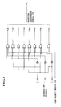
- FIG.1 is a block diagram showing the configuration of a first embodiment of an interrupt controller of the present invention.
- a flag is set, then this flag state is read out from a program, and an interrupt request signal generation state is recognized.
- an interrupt controller 1 comprises an interrupt control circuit 3 provided with an interrupt control register 2, and a channel selector 4.
- the interrupt control register 2 for inputting and outputting data which assigns the actions of the interrupt controller 1 to an external device is provided.
- the interrupt control register 2 comprises eight registers corresponding respectively to eight interrupt request signals IRO to IR7 which are assigned to the interrupt controller 1 from an external device. These eight interrupt registers are assigned through address bus signals A1, A2, and A3.
- Data which is stored in the interrupt control register 2 is organized in fields as shown in FIG.2.
- an INTV field is provided for storing an interrupt vector for outputting by the interrupt controller 1 during an interrupt acknowledge cycle.
- An INTL field is provided for storing an interrupt level value for outputting by a processor when an interrupt request is received from an external device through an interrupt request signal lRn.
- a TM bit field is provided for storing data which is set when the interrupt request signal IRn sets either an edge trigger or a level trigger.
- the TM bit field is, for example, "1”
- an edge trigger is set, and an interrupt is generated when the interrupt request signal IRn changes from a low level to a high level.
- the level trigger mode is set, and an interrupt is generated when the interrupt request signal IRn is in the low level state.
- An IE bit field is provided for indicating either approval or rejection of the generation of an interrupt through the interrupt request signal lRn.
- the interrupt controller 1 is an interrupt approval state, and an interrupt can be generated by the interrupt request signal lRn.
- the interrupt controller 1 is an interrupt rejection.
- the level trigger mode if the interrupt request signal IRn is low level during the period when the IE bit is "0”, the processor will not request an interrupt.
- the IE bit is "0" during the edge trigger mode, an input edge trigger is retained internally and the interrupt request to the processor is reserved until the IE bit next becomes "1".
- An AID bit field is for controlling whether or not the IE bit is automatically set to "0" when an interrupt request received through the interrupt request signal IRn is accepted by the processor. If the interrupt acknowledge cycle is executed while the AID bit is "1", the IE bit automatically becomes “0” and the interrupt controller 1 becomes the interrupt rejection state. This function is not used when the AID bit is "0".
- an ES bit is set to "1".
- the edge trigger mode when an edge trigger has already been generated in the interrupt request signal IRn and an interrupt has been requested, if a next edge trigger is generated in this IRn signal, "1" is set in the ES bit until the interrupt acknowledge cycle of that interrupt request is completed.
- the interrupt controller In the interrupt control circuit 3 provided with this interrupt control register 2, when the edge trigger or the level trigger is input to the interrupt control circuit 3 through the interrupt request signal lRn, the interrupt controller enters the interrupt generation state internally in the interrupt control circuit 3. In this state, if the IE bit of the interrupt control register 2 becomes "1", the interrupt level set in the INTL field is output through a plurality of interrupt request priority signals IRPO to IRP3, and an interrupt is requested from the processor. Subsequently, in the interrupt acknowledge cycle, when an interrupt acknowledge signal IACK enters the low level, the interrupt controller outputs the interrupt vector set in the INTV field of the interrupt control register 2 through a plurality of data bus signals D00 to D007, by means of the processor 1. Then, the interrupt controller is released from the interrupt generation state at the same time.
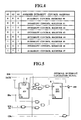
- the channel selector 4 is a circuit for generating interrupt control register assignment signals for assigning a plurality of interrupt control registers #0 to #7 corresponding to each interrupt request signal.
- a chip select signal CS and address bus signals A1 to A3 are input from an external device when the interrupt control register 2 is accessed.
- the channel selector 4 has a configuration, for example, as shown in FIG.3, and the interrupt control registers #0 to #7 are assigned respectively through the address bus signals A1 to A3, as shown in FIG.4.
- a register F/F5 is provided for maintaining the interrupt generation state, and a flip-flop F/F6 is provided corresponding to the ES bit field.
- the register F/F5 and the flip-flop F/F6 are initially set to "0".
- the interrupt request signal IRn is input to the clock CK of the register F/F5, and when an edge trigger is input to the interrupt request signal IRn with the interrupt acknowledge signal IACK at the high level, the register F/F5 is set to "1" and the interrupt controller becomes the interrupt generation state.
- the edge trigger of the interrupt request signal IRn is input to the clock CK of the register F/F5 at the same time. At this time, if an output Q of the register F/F5 is at the low level, the output Q of the flip-flop F/F6 is fed back to an input D of the flip-flop F/F6 so that the content of the register F/F5 remains "0".
- the interrupt acknowledge signal IACK is input to a CLEAR terminal CLR of the register F/F5, and when the interrupt acknowledge signal IACK is at the low level in the interrupt acknowledge cycle, the content of the register F/F5 are cleared to "0".
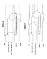
- the register F/F5 when an edge trigger is generated in the interrupt request signal lRn, the register F/F5 is set to "1" and the output Q also enters the high level. If the IE bit field of the interrupt control register 2 is "1", the value in the INTL field is output as the interrupt request priority signals IRPO to IRP3. Subsequently, when, prior to the start of the interrupt acknowledge cycle, the next edge trigger is generated in the interrupt request signal lRn, the flip-flop F/F6 is set to "1" and the output Q also becomes high level. Subsequently, when the interrupt acknowledge signal IACK is switched to the low level, the register F/F5 is cleared to "0" and the output Q also enters the low level.
- the interrupt request priority signals IRPO to IRP3 all become high level.
- the content of the flip-flop F/F6 does not change but are maintained at "1". In this way, when an edge trigger is input to the interrupt request signal IRn and an interrupt is generated, the flip-flop F/F6 can indicate that the subsequent interrupt has been requested.
- the flip-flop F/F6 corresponds to the ES bit field of the interrupt control register 2 and can be read and written by an external processor.
- a write signal WR and the chip select signal CS enter the low level, and when the leading edge of a data strobe signal DS is input, the value of the data bus signal D00 is introduced as the contents of the flip-flop F/F6.
- the write signal WR becomes high level and the value in the flip-flop F/F6 is output as the data bus signal D00.
- FIG.8 is a process flow diagram showing the processing of an interrupt when the interrupt controller 1 of the present invention is used.
- the process flow of the interrupt process shown in FIG.8 will now be described.
- the contents of the processor registers are saved (Step 100), after which th contents of the interrupt control register 2 are read out (Step 110) and the ES bit field (F/F6) is checked (Step 120). If the result of the check shows the contents of the ES bit field (F/F6) to be "0", this indicates that the interrupt processing by an edge trigger can be carried out and a normal interrupt processing is done (Step 130).
- Step 140 it is possible to select the interrupt process to suit the generation state of the interrupt request signal.
- the present invention is not limited to the embodiment described above.
- the embodiment could be modified so that the ES bit field (F/F6) is structured as a counter to count the number of times the edge trigger is input.
- the ES bit field shows whether or not a second interrupt request while the first interrupt request is generated.
- the ES bit field it is not possible to know the number of interrupts which have been generated.
- the configuration of the edge count register is illustrated in FIG.9.
- the edge count register is comprised of four bits. Read and write operations from external devices are possible, and, in such a case, either the interrupt control register or the edge count register is selected through the values of a plurality of address signals A1 to A4 as shown in FIG.10.
- the F/F5 register is maintained in the same interrupt generation state shown in FIG.6.
- a counter 7 is a four-bit counter corresponding to an ECNT field. Initially, the register F/F5 is set to "0" and the counter 7 is set to "0000".
- the interrupt request signal IRn is linked to the clock CK of the register F/F5, and when an edge trigger is input to the interrupt request signal lRn, the register F/F5 is set to "1" and the processor enters the interrupt generation state.
- a leading edge in the clock CK of the counter 7 is generated when the register F/F5 is set to "1", and a leading edge is generated in the interrupt request signal or CS, WR, and DS change from the low level state to the high level state. In the latter case, because LOAD enters the low level, the values of D12, D13, D14, and D15 are set in the counter.
- LOAD is at the high level and the contents of the counter 7 are incremented by one. If the four bits of the counter are "1111", when an edge trigger is input to CK the contents of the counter are changed to "0000". Accordingly, the counter counts from "0000" to "1111".
- CSn is at the low level and WR is at the high level
- a plurality of outputs QD, QC, QB, QA is output to the counter 7 and these are respectively output as a plurality of data bus signals D12, D13, D14, D15.
- the provision of the counter 7 makes it possible to count the number of edge triggers newly generated during an interrupt generation state. As a result, if the value in the edge count register is read out by the interrupt processing program, it is possible to recognize the number of times that an edge trigger is generated before the interrupt is processed. Therefore the interrupt processing can be changed to correspond to that number of times.
- the counter 7 has a four-bit structure and therefore can count from 0 to 15 only. However, it is possible to increase the number of bits and therefore increase the extent of the count (the number of edge triggers generated).
- the interrupt controller enters the interrupt generation state and, until that state is released, if the same interrupt request occurs this interrupt request can be detected.
- the result of the detection can therefore be referenced externally so that it is possible to recognize if the interrupt processing has not functioned normally, making it possible to process interrupts to comply with such a case.
- the reliability of the system provided with this interrupt controller can be improved.
Landscapes
- Engineering & Computer Science (AREA)
- Theoretical Computer Science (AREA)
- Physics & Mathematics (AREA)
- General Engineering & Computer Science (AREA)
- General Physics & Mathematics (AREA)
- Bus Control (AREA)
- Computer And Data Communications (AREA)
Applications Claiming Priority (2)
| Application Number | Priority Date | Filing Date | Title |
|---|---|---|---|
| JP2194714A JPH0743653B2 (ja) | 1990-07-25 | 1990-07-25 | 割込みコントローラ |
| JP194714/90 | 1990-07-25 |
Publications (3)
| Publication Number | Publication Date |
|---|---|
| EP0468454A2 true EP0468454A2 (de) | 1992-01-29 |
| EP0468454A3 EP0468454A3 (en) | 1992-05-27 |
| EP0468454B1 EP0468454B1 (de) | 1996-12-27 |
Family
ID=16329029
Family Applications (1)
| Application Number | Title | Priority Date | Filing Date |
|---|---|---|---|
| EP91112339A Expired - Lifetime EP0468454B1 (de) | 1990-07-25 | 1991-07-23 | Unterbrechungssteuerung |
Country Status (5)
| Country | Link |
|---|---|
| US (1) | US5410708A (de) |
| EP (1) | EP0468454B1 (de) |
| JP (1) | JPH0743653B2 (de) |
| KR (1) | KR940011670B1 (de) |
| DE (1) | DE69123794T2 (de) |
Cited By (4)
| Publication number | Priority date | Publication date | Assignee | Title |
|---|---|---|---|---|
| EP0884684A1 (de) * | 1997-06-13 | 1998-12-16 | Alcatel | Mehrfachunterbrechungsabwicklungsverfahren und -gerät |
| EP0812436A4 (de) * | 1995-03-01 | 1999-07-28 | Intel Corp | Interrupt-steuerung für ein computersystem |
| DE10047183A1 (de) * | 2000-09-22 | 2002-04-18 | Infineon Technologies Ag | Digitales Zwischenspeicherbauelement |
| KR100331028B1 (ko) * | 1998-11-18 | 2002-09-04 | 한국전자통신연구원 | 단일신호인터럽트방식의프로세서를위한인터럽트요구제어기및그제어방법 |
Families Citing this family (29)
| Publication number | Priority date | Publication date | Assignee | Title |
|---|---|---|---|---|
| US5894577A (en) * | 1993-09-22 | 1999-04-13 | Advanced Micro Devices, Inc. | Interrupt controller with external in-service indication for power management within a computer system |
| US6145047A (en) * | 1994-05-19 | 2000-11-07 | Vlsi Technology Inc. | Circuit and method for converting interrupt signals from level trigger mode to edge trigger mode |
| US5671421A (en) * | 1994-12-07 | 1997-09-23 | Intel Corporation | Serial interrupt bus protocol |
| US5708813A (en) * | 1994-12-12 | 1998-01-13 | Digital Equipment Corporation | Programmable interrupt signal router |
| US5943507A (en) * | 1994-12-22 | 1999-08-24 | Texas Instruments Incorporated | Interrupt routing circuits, systems and methods |
| US5640570A (en) * | 1996-01-26 | 1997-06-17 | International Business Machines Corporation | Information handling system for transmitting contents of line register from asynchronous controller to shadow register in another asynchronous controller determined by shadow register address buffer |
| US5815733A (en) * | 1996-02-01 | 1998-09-29 | Apple Computer, Inc. | System for handling interrupts in a computer system using asic reset input line coupled to set of status circuits for presetting values in the status circuits |
| US6070219A (en) * | 1996-10-09 | 2000-05-30 | Intel Corporation | Hierarchical interrupt structure for event notification on multi-virtual circuit network interface controller |
| US5819095A (en) * | 1996-12-20 | 1998-10-06 | International Business Machines Corporation | Method and apparatus for allowing an interrupt controller on an adapter to control a computer system |
| US5787290A (en) * | 1996-12-20 | 1998-07-28 | International Business Machines Corporation | Adapter with an onboard interrupt controller for controlling a computer system |
| US6003109A (en) * | 1997-08-15 | 1999-12-14 | Lsi Logic Corporation | Method and apparatus for processing interrupts in a data processing system |
| US6493781B1 (en) * | 1999-08-19 | 2002-12-10 | Koninklijke Philips Electronics N.V. | Servicing of interrupts with stored and restored flags |
| KR100528476B1 (ko) * | 2003-07-22 | 2005-11-15 | 삼성전자주식회사 | 컴퓨터 시스템의 인터럽트 처리 장치 |
| US7409483B2 (en) * | 2003-12-19 | 2008-08-05 | Intel Corporation | Methods and apparatuses to provide message signaled interrupts to level-sensitive drivers |
| US20050289271A1 (en) * | 2004-06-29 | 2005-12-29 | Martinez Alberto J | Circuitry to selectively produce MSI signals |
| JP2006277558A (ja) * | 2005-03-30 | 2006-10-12 | Fujitsu Ten Ltd | 信号変化検出装置及び信号変化検出方法 |
| US7984281B2 (en) * | 2005-10-18 | 2011-07-19 | Qualcomm Incorporated | Shared interrupt controller for a multi-threaded processor |
| US7702889B2 (en) * | 2005-10-18 | 2010-04-20 | Qualcomm Incorporated | Shared interrupt control method and system for a digital signal processor |
| US7415557B2 (en) | 2006-06-06 | 2008-08-19 | Honeywell International Inc. | Methods and system for providing low latency and scalable interrupt collection |
| JP4897851B2 (ja) * | 2009-05-14 | 2012-03-14 | インターナショナル・ビジネス・マシーンズ・コーポレーション | コンピュータ・システム及びコンピュータ・システムの制御方法 |
| US8738830B2 (en) | 2011-03-03 | 2014-05-27 | Hewlett-Packard Development Company, L.P. | Hardware interrupt processing circuit |
| US9645823B2 (en) | 2011-03-03 | 2017-05-09 | Hewlett-Packard Development Company, L.P. | Hardware controller to choose selected hardware entity and to execute instructions in relation to selected hardware entity |
| US9189283B2 (en) | 2011-03-03 | 2015-11-17 | Hewlett-Packard Development Company, L.P. | Task launching on hardware resource for client |
| JP5588951B2 (ja) * | 2011-10-28 | 2014-09-10 | 京セラドキュメントソリューションズ株式会社 | 割り込み制御回路 |
| JP5622284B2 (ja) * | 2011-12-28 | 2014-11-12 | 京セラドキュメントソリューションズ株式会社 | 割り込み監視回路 |
| JP6008745B2 (ja) * | 2013-01-15 | 2016-10-19 | ルネサスエレクトロニクス株式会社 | データ処理装置 |
| JP6582503B2 (ja) * | 2015-04-08 | 2019-10-02 | 富士通株式会社 | 情報処理装置 |
| CN111506530A (zh) * | 2019-01-30 | 2020-08-07 | 智原科技股份有限公司 | 中断管理系统及其管理方法 |
| CN112948314B (zh) * | 2021-03-04 | 2025-02-14 | 北京灵汐科技有限公司 | 中断控制器和核间通信系统 |
Family Cites Families (14)
| Publication number | Priority date | Publication date | Assignee | Title |
|---|---|---|---|---|
| JPS5549344B2 (de) * | 1973-12-19 | 1980-12-11 | ||
| US4091447A (en) * | 1976-07-19 | 1978-05-23 | Union Carbide Corporation | Interrupt control system for a microcomputer |
| US4080649A (en) * | 1976-12-16 | 1978-03-21 | Honeywell Information Systems Inc. | Balancing the utilization of I/O system processors |
| US4177513A (en) * | 1977-07-08 | 1979-12-04 | International Business Machines Corporation | Task handling apparatus for a computer system |
| US4470111A (en) * | 1979-10-01 | 1984-09-04 | Ncr Corporation | Priority interrupt controller |
| IT1193650B (it) * | 1983-01-31 | 1988-07-21 | Honeywell Inf Systems | Apparato di interruzione ad affidabilita' accresciuta |
| US4636944A (en) * | 1984-01-17 | 1987-01-13 | Concurrent Computer Corporation | Multi-level priority micro-interrupt controller |
| JPS60176145A (ja) * | 1984-02-23 | 1985-09-10 | Fujitsu Ltd | 割込み処理回路 |
| US4761732A (en) * | 1985-11-29 | 1988-08-02 | American Telephone And Telegraph Company, At&T Bell Laboratories | Interrupt controller arrangement for mutually exclusive interrupt signals in data processing systems |
| US5230048A (en) * | 1986-09-03 | 1993-07-20 | Wang Laboratories, Inc. | Data processing system with tree and list data structure |
| JPH01246602A (ja) * | 1988-03-29 | 1989-10-02 | Mitsubishi Electric Corp | プログラマブルコントローラ用特殊機能ユニット |
| US4862409A (en) * | 1988-06-13 | 1989-08-29 | Advanced Micro Devices, Inc. | Asynchronous interrupt status bit circuit |
| JPH0268632A (ja) * | 1988-09-05 | 1990-03-08 | Toshiba Corp | 割込み制御装置 |
| US5101497A (en) * | 1988-09-09 | 1992-03-31 | Compaq Computer Corporation | Programmable interrupt controller |
-
1990
- 1990-07-25 JP JP2194714A patent/JPH0743653B2/ja not_active Expired - Fee Related
-
1991
- 1991-07-19 US US07/733,121 patent/US5410708A/en not_active Expired - Fee Related
- 1991-07-23 EP EP91112339A patent/EP0468454B1/de not_active Expired - Lifetime
- 1991-07-23 DE DE69123794T patent/DE69123794T2/de not_active Expired - Fee Related
- 1991-07-24 KR KR1019910012666A patent/KR940011670B1/ko not_active Expired - Fee Related
Cited By (5)
| Publication number | Priority date | Publication date | Assignee | Title |
|---|---|---|---|---|
| EP0812436A4 (de) * | 1995-03-01 | 1999-07-28 | Intel Corp | Interrupt-steuerung für ein computersystem |
| EP0884684A1 (de) * | 1997-06-13 | 1998-12-16 | Alcatel | Mehrfachunterbrechungsabwicklungsverfahren und -gerät |
| US6272585B1 (en) | 1997-06-13 | 2001-08-07 | Alcatel | Multiple interrupt handling method and apparatus |
| KR100331028B1 (ko) * | 1998-11-18 | 2002-09-04 | 한국전자통신연구원 | 단일신호인터럽트방식의프로세서를위한인터럽트요구제어기및그제어방법 |
| DE10047183A1 (de) * | 2000-09-22 | 2002-04-18 | Infineon Technologies Ag | Digitales Zwischenspeicherbauelement |
Also Published As
| Publication number | Publication date |
|---|---|
| JPH0481932A (ja) | 1992-03-16 |
| DE69123794D1 (de) | 1997-02-06 |
| KR920003174A (ko) | 1992-02-29 |
| DE69123794T2 (de) | 1997-05-15 |
| EP0468454B1 (de) | 1996-12-27 |
| JPH0743653B2 (ja) | 1995-05-15 |
| US5410708A (en) | 1995-04-25 |
| KR940011670B1 (ko) | 1994-12-23 |
| EP0468454A3 (en) | 1992-05-27 |
Similar Documents
| Publication | Publication Date | Title |
|---|---|---|
| EP0468454A2 (de) | Unterbrechungssteuerung | |
| US4405952A (en) | Apparatus for detecting faulty sectors and for allocating replacement sectors in a magnetic disc memory | |
| US5036460A (en) | Microprocessor having miswriting preventing function | |
| US4873667A (en) | FIFO buffer controller | |
| US5243561A (en) | Data erasing and re-writing circuit for use in microcomputer integrated circuit device | |
| EP0088982B1 (de) | Mikrocomputersystem mit Puffer in einer peripheren Speichersteuerung | |
| US5285415A (en) | Data counting memory card and reader | |
| US4104682A (en) | Apparatus for reducing the number of undetected errors read along the length of a binary information bearing medium | |
| US6473841B1 (en) | Signal processing apparatus with memory access history storage | |
| EP0327115B1 (de) | Speichersytem mit Serienzugriff mit einer Kaskaden-Pufferschaltung | |
| US5247640A (en) | Dual access control system including plural magnetic disk control units and contention control circuitry | |
| US5561672A (en) | Apparatus for preventing computer data destructively read out from storage unit | |
| EP0463352B1 (de) | Schaltungsinnerer Emulatormikroprozessor mit getrenntem Nutzer- und Schaltungsinnerem Emulatorspeicher | |
| JP2600376B2 (ja) | メモリ制御装置 | |
| JP3887059B2 (ja) | データ書き込み方法、データ読み出し方法、及びメモリ回路 | |
| KR100380601B1 (ko) | 아이피씨용 에프아이에프오의 번지 관리 시스템 및 방법 | |
| JPH0226068Y2 (de) | ||
| JP2507634B2 (ja) | 情報処理装置 | |
| JPH03208158A (ja) | 電子制御装置 | |
| JPS6318776B2 (de) | ||
| SU1211735A1 (ru) | Устройство дл контрол хода программы | |
| JPH0793505A (ja) | 計数積算装置 | |
| JPS63103330A (ja) | アドレススタツク使用ミス検出方式 | |
| JPS62166449A (ja) | 論理装置の履歴記憶装置 | |
| JPS6117012B2 (de) |
Legal Events
| Date | Code | Title | Description |
|---|---|---|---|
| PUAI | Public reference made under article 153(3) epc to a published international application that has entered the european phase |
Free format text: ORIGINAL CODE: 0009012 |
|
| 17P | Request for examination filed |
Effective date: 19910723 |
|
| AK | Designated contracting states |
Kind code of ref document: A2 Designated state(s): DE FR GB |
|
| PUAL | Search report despatched |
Free format text: ORIGINAL CODE: 0009013 |
|
| AK | Designated contracting states |
Kind code of ref document: A3 Designated state(s): DE FR GB |
|
| 17Q | First examination report despatched |
Effective date: 19950606 |
|
| GRAG | Despatch of communication of intention to grant |
Free format text: ORIGINAL CODE: EPIDOS AGRA |
|
| GRAH | Despatch of communication of intention to grant a patent |
Free format text: ORIGINAL CODE: EPIDOS IGRA |
|
| RAP1 | Party data changed (applicant data changed or rights of an application transferred) |
Owner name: KABUSHIKI KAISHA TOSHIBA |
|
| GRAH | Despatch of communication of intention to grant a patent |
Free format text: ORIGINAL CODE: EPIDOS IGRA |
|
| GRAA | (expected) grant |
Free format text: ORIGINAL CODE: 0009210 |
|
| AK | Designated contracting states |
Kind code of ref document: B1 Designated state(s): DE FR GB |
|
| REF | Corresponds to: |
Ref document number: 69123794 Country of ref document: DE Date of ref document: 19970206 |
|
| ET | Fr: translation filed | ||
| PLBE | No opposition filed within time limit |
Free format text: ORIGINAL CODE: 0009261 |
|
| STAA | Information on the status of an ep patent application or granted ep patent |
Free format text: STATUS: NO OPPOSITION FILED WITHIN TIME LIMIT |
|
| 26N | No opposition filed | ||
| REG | Reference to a national code |
Ref country code: GB Ref legal event code: 746 Effective date: 19981015 |
|
| REG | Reference to a national code |
Ref country code: FR Ref legal event code: D6 |
|
| REG | Reference to a national code |
Ref country code: GB Ref legal event code: IF02 |
|
| PGFP | Annual fee paid to national office [announced via postgrant information from national office to epo] |
Ref country code: GB Payment date: 20060719 Year of fee payment: 16 Ref country code: FR Payment date: 20060719 Year of fee payment: 16 |
|
| PGFP | Annual fee paid to national office [announced via postgrant information from national office to epo] |
Ref country code: DE Payment date: 20060720 Year of fee payment: 16 |
|
| GBPC | Gb: european patent ceased through non-payment of renewal fee |
Effective date: 20070723 |
|
| PG25 | Lapsed in a contracting state [announced via postgrant information from national office to epo] |
Ref country code: DE Free format text: LAPSE BECAUSE OF NON-PAYMENT OF DUE FEES Effective date: 20080201 |
|
| PG25 | Lapsed in a contracting state [announced via postgrant information from national office to epo] |
Ref country code: GB Free format text: LAPSE BECAUSE OF NON-PAYMENT OF DUE FEES Effective date: 20070723 |
|
| REG | Reference to a national code |
Ref country code: FR Ref legal event code: ST Effective date: 20080331 |
|
| PG25 | Lapsed in a contracting state [announced via postgrant information from national office to epo] |
Ref country code: FR Free format text: LAPSE BECAUSE OF NON-PAYMENT OF DUE FEES Effective date: 20070731 |