EP0470880B1 - Dispositif pour l'échange dynamique de processeur de service - Google Patents
Dispositif pour l'échange dynamique de processeur de service Download PDFInfo
- Publication number
- EP0470880B1 EP0470880B1 EP91402069A EP91402069A EP0470880B1 EP 0470880 B1 EP0470880 B1 EP 0470880B1 EP 91402069 A EP91402069 A EP 91402069A EP 91402069 A EP91402069 A EP 91402069A EP 0470880 B1 EP0470880 B1 EP 0470880B1
- Authority
- EP
- European Patent Office
- Prior art keywords
- cmu
- service processor
- maintenance unit
- service
- file
- Prior art date
- Legal status (The legal status is an assumption and is not a legal conclusion. Google has not performed a legal analysis and makes no representation as to the accuracy of the status listed.)
- Expired - Lifetime
Links
Images


Classifications
-
- G—PHYSICS
- G06—COMPUTING OR CALCULATING; COUNTING
- G06F—ELECTRIC DIGITAL DATA PROCESSING
- G06F11/00—Error detection; Error correction; Monitoring
- G06F11/22—Detection or location of defective computer hardware by testing during standby operation or during idle time, e.g. start-up testing
- G06F11/26—Functional testing
- G06F11/273—Tester hardware, i.e. output processing circuits
- G06F11/2736—Tester hardware, i.e. output processing circuits using a dedicated service processor for test
-
- G—PHYSICS
- G06—COMPUTING OR CALCULATING; COUNTING
- G06F—ELECTRIC DIGITAL DATA PROCESSING
- G06F11/00—Error detection; Error correction; Monitoring
- G06F11/07—Responding to the occurrence of a fault, e.g. fault tolerance
- G06F11/16—Error detection or correction of the data by redundancy in hardware
- G06F11/20—Error detection or correction of the data by redundancy in hardware using active fault-masking, e.g. by switching out faulty elements or by switching in spare elements
-
- G—PHYSICS
- G06—COMPUTING OR CALCULATING; COUNTING
- G06F—ELECTRIC DIGITAL DATA PROCESSING
- G06F11/00—Error detection; Error correction; Monitoring
- G06F11/30—Monitoring
- G06F11/32—Monitoring with visual or acoustical indication of the functioning of the machine
Definitions
- the present invention relates to an architecture for dynamic exchange of service processor.
- the emergency service processor In a redundant configuration of a system, there are two service processors: one is the tenant, it is the one that performs the service functions at a given time; the other is that of backup available to perform the service functions in the event that the tenant fails.
- the emergency service processor As the hardware becomes more and more reliable, the emergency service processor is not very often used (it remains useful for system availability around 100%, however). The emergency service processor is therefore unused most of the time.
- the backup service processor in its moments of non-activity, nm not as such, but as a screen to give the possibility to an operator of operate a service function from the tenant screen and another operator operate another service function from the standby service processor screen.
- a first object of the invention is to propose a device allowing a dynamic exchange of service processor, as claimed in claim 1.
- the device allowing a dynamic exchange of service processor, comprises a first service processor connected by a network and a central system maintenance unit (CMU) to a central system (4), said service processor (1) is connected to a second reserve service processor (2) by the network and the maintenance unit (CMU) is characterized in that each service processor additionally comprises operating system programs , a supervisor program and at least one service broken down into two applications, one "body” composed of the program algorithm, the other "presentation” comprising the operator interface allowing a window type display with a menu bar, and means (MSH 10, 20) for processing communications with the other service processors, via the maintenance unit (CMU), a supervisor program managing the service instance numbers and starting the services, said supervisor program having access to a system configuration table,
- the maintenance unit comprises a random access memory (400) which communicates via the central system with a storage means of the central system, which contains the configuration table of the IRT system (resource installation table), and what the supervisor of the holding service processor and of the standby service processor contains a routine (LBCAM) of access method to the maintenance unit (CMU) for accessing the system configuration table contained in the means of central system storage, transfer it to its own disk (16) and load it into the RAM of the maintenance unit.
- LBCAM routine of access method to the maintenance unit (CMU) for accessing the system configuration table contained in the means of central system storage, transfer it to its own disk (16) and load it into the RAM of the maintenance unit.
- the device is characterized in that the supervisor program of the standby service processor contains a routine for, in the event of a failure signaled by an event sent by the maintenance unit (CMU) to the standby service processor , launch the supervisor program of the standby service processor, and by the access method routine (LBCAM) read the configuration table (IRT, ECF) in the RAM (400) of the maintenance unit to copy it into the hard drive (26) of the standby service processor (2).
- the supervisor program of the standby service processor contains a routine for, in the event of a failure signaled by an event sent by the maintenance unit (CMU) to the standby service processor , launch the supervisor program of the standby service processor, and by the access method routine (LBCAM) read the configuration table (IRT, ECF) in the RAM (400) of the maintenance unit to copy it into the hard drive (26) of the standby service processor (2).
- the random access memory is divided into two parts; a first accessible only by a processor of the maintenance unit (CMU), a second, (MSP), accessible only by the coprocessor of the maintenance unit (CMU), in execution of messages sent by the routine of method d access to the maintenance unit (CMU) launched by a service running on the service processor.
- the routine of the access method displays the message "file not found” in the case where the flag was set to 1 and proceeds to copy the file, either from the CMU in the disk, or in reverse.
- the routine of the access method displays the message "file unknown" in the case where the name of the file does not exist in the directory of the maintenance unit (CMU) and proceeds to copy it s 'exists in the service processor disk.
- CMU maintenance unit
- the files managed by the access method of the maintenance unit (CMU) are copied from the hard disk to the random access memory of the maintenance unit (CMU) when the hardware interface plate has been shutdown.
- the files managed by the access method of the maintenance unit (CMU) are copied from the random access memory of the maintenance unit (CMU) to the hard disk of a service processor when a service processor is initialized.
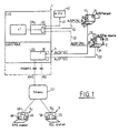
- the architecture of the system is constituted as shown in FIG. 1 by a service processor holding (1), connected by an interface software (10) MSH (Maintenance Station Handler) with a line for processing maintenance of the stations of telecommunications (12) forming a STARLAN type network.
- This line (12) is connected to a clock and maintenance unit CMU (40) which ensures communications between the processor service (1), a second standby service processor (2), via a second line (22), and a central system (41).
- the maintenance and clock unit (CMU) also communicates by a line (43) with a set of maintenance processors (42).
- the service processor holding (1) and the service processor standby (2) also communicate via a remote line management interface (11) RLH (Remote Line Handler), and respectively (21), with a service console switch (3), which makes it possible, by means of a circuit (30), and an appropriate switching matrix, to put each of the service processors into communication with the telecommunications network of a given country, and through this network with a station (5) constituting a remote service console communicating with this network (52) via RSC interface software (50).
- each of the service processors can be put in communication, through the network (52), with a remote maintenance station (6) communicating with the network (52) by an RMS interface software (51).
- the lines (23) and (13) connected to the service console switch by the interface software (21) and (11) have bit rates of 4,800 baud, while the lines (12) and (22) form the network "STARLAN" with the clock and maintenance unit (40) have speeds of the order of megabits per second.
- the maintenance processors (42) are connected to sets of input-output units for the central system.
- FIG. 2 represents the software environment enabling the service processors (1, 2) to communicate via the "STARLAN" network with the maintenance unit CMU (40).
- the service processor holding comprises in addition to the MSH software (10) and an operating system comprising the operating system of the MS-DOS disk, multitasking window software such as WINDOWS, and a part of software that the '' we will describe later.
- the service processor holding also includes a communication software "NETBIOS” (100) communicating through a network card type "STARLAN” (14) and a piece of hardware (101) constituting a gateway (HUB), through the line (12) from the STARLAN network, to a second gateway (400), a management circuit (401), software for interfacing with the STARLAN "NETBIOS” network (402) and software for interfacing (403) with the processor RSPI service.
- the standby service processor (2) will also have the same elements, but with the digit 2 as a reference for the tens or hundreds digit.
- Each service processor comprises in addition to its operating system (15, 25) a body program for a given application (17, 27, fig. 1) and a program presenting the application (18, 28, fig. 1 ).
- SPV supervisor software manages the instance numbers of the installed services and starts the services.
- the holding and standby service processors boot separately in parallel.
- the difference between a standby service processor and a standby service processor is that the standby service processor accepts the initiation of services while the standby service processor waits for an event from the CMU telling it to become a standby.
- the supervisor SPV of the service processor holding (1) sends, via the CMU an event to the second service processor (2) in the event of failure of the first, which allows the latter to establish the same applications.
- FIG. 3 represents the principle of an architecture necessary for the implementation of the invention in which the body program (17) of a given application, running for example on the service processor holding, exchanging lines of text and acknowledgment or response messages with the program presentation (18) of the application.
- These exchanges of messages and lines of text are done via library management modules for LBXMS (171) and LPXMS (183) messages which are linked respectively to the body of the application for LBXMS, and to the presentation. of the application for LPXMS.
- the presentation program of the application exchanges with the WINDOWS software (150), the primitives necessary for the management of tasks and the display of windows.
- the presentation application will have been developed using the WINDOWS (150) program which can be seen as a set of four components.
- a first kernel component (Kernel) (151) providing task management, memory allocations, the clock function (TIMER) and dynamic links.
- a second user element (152) (USER) used to manage the windows and create them.
- a third element (GDI) (153) makes it possible to carry out the graphic functions in order to carry out drawings,
- a fourth element (154) COM which is a WINDOWS driver, makes it possible to manage asynchronous lines of the RS 232 type and a protocol data exchange between DDE applications (dynamic data exchange) allows communication between applications.
- FIG. 4 represents the software necessary for the installation of means allowing the dynamic exchange of service processor.
- the CMU (40) is connected by a STARLAN type connection to the MSH software (10) or (20) depending on whether it belongs to the service processor or the standby.
- the MSH application dialogs with a VSH (VMP Object Sequence Handler) library (or utility) for processing object sequence of the constituent VMP program the Virtual Maintenance Panel.
- VSH VMP Object Sequence Handler
- the SYC service calls CAM (CMU file access method) to update the IRT files.
- CAM itself calls VSH to execute VOS (sequences of virtual objects) to save the files in the memory (400, 401) of the CMU and the hard disk of the service processor holding (16) or reserve (26) ).
- This utility has two modules; one LBCAM which is the "body”, the other LPCAM which the corresponding "presentation module” and interacting with the WINDOWS User software (152) to ensure the presentation on the screen.
- the service body (105) can be the program body of the virtual maintenance panel (VMP) and the service presentation (104) can be the VMP presentation.
- the maintenance panel (VMP) allows you to use specific commands, dynamically view selected resources, build and compile directives and execute them, display the list of files, use a tutor to build field by field command line and allow operations such as read-write registers, read-write memories, etc.
- LBCAM (103) allows access, thanks to the file of the MS-DOS system (15), to the hard disk (16), either in reading, or in writing according to the case.
- This architecture allows the standby service processor (2) to be used as a station for running the presentation of an application, while allowing the system to be taken over by the standby service processor supervisor (2 ), in the event that the holding service processor fails.
- the supervisor SPV (1052) of the service processor holding (1) requests the launch on the standby service processor (2) of the body application running on the holding service processor (1) with or without interrupting the presentation in progress, as the case may be.
- the system configuration table which in the state of the art was stored on the disk of the holding service processor, is, for the purposes of the invention, upon initialization of the system generated on a system disk (7) and not on a service processor disk, then the configuration table is transferred to the service processor (1) when the system is initialized for the first time.
- the service processor (1) copies this table to the part (MSP) of the RAM (400) of the hardware interface plate (40) which becomes the reference, that is to say that the service processor ( 1) accesses RAM when using the configuration table.
- the two service processors each have a path to this RAM.
- this table is copied in parallel to a file on the disk (10) holding service processor (1) in order to be able to possibly reset the RAM (400) when the hardware interface plate (40) has been, for some reason, shutdown.
- This architecture allows a dynamic exchange of service processor.
- a new service processor When a new service processor is connected, it copies the configuration table from RAM to its disk. The same operation is performed when switching from the holding service processor (1) to the standby service processor (2).
- the CAM software accesses the CMU directory label file to determine if a file is contained or no.
- the file label format consists of bits 0 to 7 for the file name, by bits 8 to 10 for the name of an extension file, by bit 11 to designate whether the allocated space is fixed or variable, by bits 12 to 15 to indicate the space allocated in number of bytes, by bits 16 to 19 to indicate the current size of the file in number of bytes, by bits 20 to 23 to indicate l start address of the file, by bits 24 to 29 to indicate the creation date.
- bits 30 and 31 constitute a flag initialized to zero and set to the value -1 each time the file is being written. Once the writing session has ended, the flag is reset. This is protection against abnormal write ends.
- the CAM module returns the code "file not found”. If the name of a file is not found by CAM when it is asked to access a certain file, the latter returns the code "file unknown”.
- the CAM access method returns the following message "file not found” if the file is not present, neither in the memory of the CMU, nor in the hard disk of the service processor holding it. In the case where the file is present in the CMU memory, but not in the service processor hard disk, the access method returns the message "CMU memory. Update of the hard disk”. In the opposite case, the access method returns the message "hard disk-service processor. Update of the CMU".
- the access method In the case where the files are present in the CMU memory and in the hard disk, the access method returns the message "CMU memory". Whenever necessary, the access method updates the corresponding element. Besides ECF and IRT files for standby and standby service processors, the access method also manages the system reconfiguration table, the reservation lists ROLST, R1LSI for the standby and standby service processors, the exclusion list EX.LST and the diagnostic list DG.LST, as well as the initialization parameters of the service processors S0 and S1 contained in the file INIT PAR.
Landscapes
- Engineering & Computer Science (AREA)
- Theoretical Computer Science (AREA)
- General Engineering & Computer Science (AREA)
- Quality & Reliability (AREA)
- Physics & Mathematics (AREA)
- General Physics & Mathematics (AREA)
- Computer Hardware Design (AREA)
- Hardware Redundancy (AREA)
- Multi Processors (AREA)
- Exchange Systems With Centralized Control (AREA)
- Telephonic Communication Services (AREA)
- Computer And Data Communications (AREA)
Applications Claiming Priority (2)
| Application Number | Priority Date | Filing Date | Title |
|---|---|---|---|
| FR9010180A FR2665778B1 (fr) | 1990-08-09 | 1990-08-09 | Architecture pour echange dynamique de processeur de service. |
| FR9010180 | 1990-08-09 |
Publications (2)
| Publication Number | Publication Date |
|---|---|
| EP0470880A1 EP0470880A1 (fr) | 1992-02-12 |
| EP0470880B1 true EP0470880B1 (fr) | 1996-10-30 |
Family
ID=9399570
Family Applications (1)
| Application Number | Title | Priority Date | Filing Date |
|---|---|---|---|
| EP91402069A Expired - Lifetime EP0470880B1 (fr) | 1990-08-09 | 1991-07-24 | Dispositif pour l'échange dynamique de processeur de service |
Country Status (8)
| Country | Link |
|---|---|
| EP (1) | EP0470880B1 (es) |
| JP (1) | JPH0664570B2 (es) |
| AT (1) | ATE144847T1 (es) |
| CA (1) | CA2067189C (es) |
| DE (1) | DE69122924T2 (es) |
| ES (1) | ES2095924T3 (es) |
| FR (1) | FR2665778B1 (es) |
| WO (1) | WO1992002878A1 (es) |
Families Citing this family (1)
| Publication number | Priority date | Publication date | Assignee | Title |
|---|---|---|---|---|
| US5513351A (en) * | 1994-07-28 | 1996-04-30 | International Business Machines Corporation | Protecting a system during system maintenance by usage of temporary filenames in an alias table |
Citations (1)
| Publication number | Priority date | Publication date | Assignee | Title |
|---|---|---|---|---|
| EP0445034A1 (fr) * | 1990-02-28 | 1991-09-04 | Bull S.A. | Dispositif et utilisation de ce dispositif dans un procédé de remplacement de cartes |
Family Cites Families (5)
| Publication number | Priority date | Publication date | Assignee | Title |
|---|---|---|---|---|
| US4014005A (en) * | 1976-01-05 | 1977-03-22 | International Business Machines Corporation | Configuration and control unit for a heterogeneous multi-system |
| US4455601A (en) * | 1981-12-31 | 1984-06-19 | International Business Machines Corporation | Cross checking among service processors in a multiprocessor system |
| JPS6272248A (ja) * | 1985-09-25 | 1987-04-02 | Hitachi Ltd | デ−タ伝送システムの現用予備切替方法 |
| US4894828A (en) * | 1987-12-22 | 1990-01-16 | Amdahl Corporation | Multiple sup swap mechanism |
| FR2633413B1 (fr) * | 1988-06-22 | 1994-07-08 | Bull Sa | Procede pour la generation de fenetres de dialogue visualisables sur l'ecran d'un systeme informatique et dispositif pour mettre en oeuvre ce procede |
-
1990
- 1990-08-09 FR FR9010180A patent/FR2665778B1/fr not_active Expired - Fee Related
-
1991
- 1991-07-24 WO PCT/FR1991/000613 patent/WO1992002878A1/fr not_active Ceased
- 1991-07-24 JP JP3512796A patent/JPH0664570B2/ja not_active Expired - Fee Related
- 1991-07-24 DE DE69122924T patent/DE69122924T2/de not_active Expired - Fee Related
- 1991-07-24 ES ES91402069T patent/ES2095924T3/es not_active Expired - Lifetime
- 1991-07-24 EP EP91402069A patent/EP0470880B1/fr not_active Expired - Lifetime
- 1991-07-24 CA CA002067189A patent/CA2067189C/fr not_active Expired - Fee Related
- 1991-07-24 AT AT91402069T patent/ATE144847T1/de not_active IP Right Cessation
Patent Citations (1)
| Publication number | Priority date | Publication date | Assignee | Title |
|---|---|---|---|---|
| EP0445034A1 (fr) * | 1990-02-28 | 1991-09-04 | Bull S.A. | Dispositif et utilisation de ce dispositif dans un procédé de remplacement de cartes |
Also Published As
| Publication number | Publication date |
|---|---|
| JPH04505680A (ja) | 1992-10-01 |
| EP0470880A1 (fr) | 1992-02-12 |
| FR2665778B1 (fr) | 1993-06-18 |
| CA2067189C (fr) | 1995-05-23 |
| ATE144847T1 (de) | 1996-11-15 |
| WO1992002878A1 (fr) | 1992-02-20 |
| CA2067189A1 (fr) | 1992-02-10 |
| DE69122924D1 (de) | 1996-12-05 |
| JPH0664570B2 (ja) | 1994-08-22 |
| DE69122924T2 (de) | 1997-03-06 |
| FR2665778A1 (fr) | 1992-02-14 |
| ES2095924T3 (es) | 1997-03-01 |
Similar Documents
| Publication | Publication Date | Title |
|---|---|---|
| US6871322B2 (en) | Method and apparatus for providing user support through an intelligent help agent | |
| EP0012886B1 (fr) | Unité de commande d'entrée/sortie pour système de traitement de données | |
| EP0820013B1 (fr) | Procédé de surveillance en temps réel d'un système informatique pour son administration et l'aide à sa maintenance en phase d'exploitation | |
| US6490690B1 (en) | Method and apparatus for unix system catastrophic recovery aid | |
| KR100350141B1 (ko) | 매체관리자,애플리케이션프로그램인터페이스와이를구현하는방법 | |
| JP4195209B2 (ja) | ストレージ・エリア・ネットワークの構成を自動化する方法およびシステム | |
| EP0021917B1 (fr) | Concentrateur téléinformatique pour réseau de transmission et de commutation de données par paquets | |
| EP0394114B1 (fr) | Coupleur multifonctions entre une unité centrale d'ordinateur et les différents organes périphériques de ce dernier | |
| EP0853412B1 (en) | System method for efficiently transferring datastreams in a multimedia system | |
| FR2702579A1 (fr) | Dispositif de communication entre au moins un client et au moins un serveur, procédé d'utilisation du dispositif et utilisation du dispositif. | |
| WO2009153498A1 (fr) | Procede de generation de requetes de manipulation d'une base de donnees d'initialisation et d'administration d'une grappe de serveurs, support de donnees et grappe de serveurs correspondants | |
| KR20010007111A (ko) | 데이터 프로세서 제어형 데이터 저장 시스템, 동적재동기화 방법 및 컴퓨터 프로그램 | |
| US5774642A (en) | Architecture for dynamic service processor exchange providing multitasking environment where multiple processors have access to a system configuration table | |
| EP0445034B1 (fr) | Dispositif et utilisation de ce dispositif dans un procédé de remplacement de cartes | |
| EP0102434B1 (fr) | Dispositif pour signaler à l'unité de commande centrale d'un équipement de traitement de données, les erreurs se produisant dans les adaptateurs | |
| US6151709A (en) | Processes and apparatuses for uploading instructions to a computer | |
| US5781902A (en) | Method, computer program product, and system for extending the capabilities of an existing process to store and display foreign data | |
| EP0524071A1 (fr) | Système d'exploitation pour dispositif universel de couplage d'un bus d'ordinateur à une liaison spécifique d'un réseau | |
| EP0969625A1 (fr) | Agent de communication entre un administrateur et au moins une ressource d'un système informatique | |
| EP0470880B1 (fr) | Dispositif pour l'échange dynamique de processeur de service | |
| CN115576705A (zh) | 一种冗余固件的数据同步方法、装置及介质 | |
| US6536039B2 (en) | Software for seamless interconnectivity between active program modules on integrated arrangement of CD drive, data server, and PC hard disk drive | |
| US20030163780A1 (en) | Enhancing management of a distributed computer system | |
| EP1341087A1 (fr) | Procédé et système de gestion d'un journal personnel d'évènements | |
| KR20020065143A (ko) | Pc 장애 자동 진단과 복구 방법 및 그 장치 |
Legal Events
| Date | Code | Title | Description |
|---|---|---|---|
| PUAI | Public reference made under article 153(3) epc to a published international application that has entered the european phase |
Free format text: ORIGINAL CODE: 0009012 |
|
| 17P | Request for examination filed |
Effective date: 19910930 |
|
| AK | Designated contracting states |
Kind code of ref document: A1 Designated state(s): AT BE CH DE DK ES FR GB GR IT LI LU NL SE |
|
| RAP3 | Party data changed (applicant data changed or rights of an application transferred) |
Owner name: BULL S.A. |
|
| 17Q | First examination report despatched |
Effective date: 19941215 |
|
| GRAG | Despatch of communication of intention to grant |
Free format text: ORIGINAL CODE: EPIDOS AGRA |
|
| GRAH | Despatch of communication of intention to grant a patent |
Free format text: ORIGINAL CODE: EPIDOS IGRA |
|
| GRAH | Despatch of communication of intention to grant a patent |
Free format text: ORIGINAL CODE: EPIDOS IGRA |
|
| GRAA | (expected) grant |
Free format text: ORIGINAL CODE: 0009210 |
|
| AK | Designated contracting states |
Kind code of ref document: B1 Designated state(s): AT BE CH DE DK ES FR GB GR IT LI LU NL SE |
|
| PG25 | Lapsed in a contracting state [announced via postgrant information from national office to epo] |
Ref country code: NL Free format text: LAPSE BECAUSE OF FAILURE TO SUBMIT A TRANSLATION OF THE DESCRIPTION OR TO PAY THE FEE WITHIN THE PRESCRIBED TIME-LIMIT Effective date: 19961030 Ref country code: GR Free format text: LAPSE BECAUSE OF FAILURE TO SUBMIT A TRANSLATION OF THE DESCRIPTION OR TO PAY THE FEE WITHIN THE PRESCRIBED TIME-LIMIT Effective date: 19961030 Ref country code: DK Effective date: 19961030 Ref country code: AT Effective date: 19961030 |
|
| REF | Corresponds to: |
Ref document number: 144847 Country of ref document: AT Date of ref document: 19961115 Kind code of ref document: T |
|
| GBT | Gb: translation of ep patent filed (gb section 77(6)(a)/1977) |
Effective date: 19961030 |
|
| REF | Corresponds to: |
Ref document number: 69122924 Country of ref document: DE Date of ref document: 19961205 |
|
| ITF | It: translation for a ep patent filed | ||
| PG25 | Lapsed in a contracting state [announced via postgrant information from national office to epo] |
Ref country code: SE Effective date: 19970130 |
|
| REG | Reference to a national code |
Ref country code: ES Ref legal event code: FG2A Ref document number: 2095924 Country of ref document: ES Kind code of ref document: T3 |
|
| NLV1 | Nl: lapsed or annulled due to failure to fulfill the requirements of art. 29p and 29m of the patents act | ||
| PG25 | Lapsed in a contracting state [announced via postgrant information from national office to epo] |
Ref country code: LI Free format text: LAPSE BECAUSE OF NON-PAYMENT OF DUE FEES Effective date: 19970731 Ref country code: CH Free format text: LAPSE BECAUSE OF NON-PAYMENT OF DUE FEES Effective date: 19970731 Ref country code: LU Free format text: LAPSE BECAUSE OF NON-PAYMENT OF DUE FEES Effective date: 19970731 |
|
| PLBE | No opposition filed within time limit |
Free format text: ORIGINAL CODE: 0009261 |
|
| STAA | Information on the status of an ep patent application or granted ep patent |
Free format text: STATUS: NO OPPOSITION FILED WITHIN TIME LIMIT |
|
| 26N | No opposition filed | ||
| REG | Reference to a national code |
Ref country code: CH Ref legal event code: PL |
|
| REG | Reference to a national code |
Ref country code: GB Ref legal event code: IF02 |
|
| PGFP | Annual fee paid to national office [announced via postgrant information from national office to epo] |
Ref country code: ES Payment date: 20050707 Year of fee payment: 15 |
|
| PGFP | Annual fee paid to national office [announced via postgrant information from national office to epo] |
Ref country code: GB Payment date: 20060627 Year of fee payment: 16 |
|
| PGFP | Annual fee paid to national office [announced via postgrant information from national office to epo] |
Ref country code: BE Payment date: 20060628 Year of fee payment: 16 |
|
| PGFP | Annual fee paid to national office [announced via postgrant information from national office to epo] |
Ref country code: DE Payment date: 20060630 Year of fee payment: 16 |
|
| BERE | Be: lapsed |
Owner name: S.A. *BULL Effective date: 20070731 |
|
| PGFP | Annual fee paid to national office [announced via postgrant information from national office to epo] |
Ref country code: IT Payment date: 20070726 Year of fee payment: 17 |
|
| GBPC | Gb: european patent ceased through non-payment of renewal fee |
Effective date: 20070724 |
|
| PG25 | Lapsed in a contracting state [announced via postgrant information from national office to epo] |
Ref country code: DE Free format text: LAPSE BECAUSE OF NON-PAYMENT OF DUE FEES Effective date: 20080201 |
|
| PG25 | Lapsed in a contracting state [announced via postgrant information from national office to epo] |
Ref country code: GB Free format text: LAPSE BECAUSE OF NON-PAYMENT OF DUE FEES Effective date: 20070724 |
|
| PG25 | Lapsed in a contracting state [announced via postgrant information from national office to epo] |
Ref country code: BE Free format text: LAPSE BECAUSE OF NON-PAYMENT OF DUE FEES Effective date: 20070731 |
|
| REG | Reference to a national code |
Ref country code: ES Ref legal event code: FD2A Effective date: 20070725 |
|
| PG25 | Lapsed in a contracting state [announced via postgrant information from national office to epo] |
Ref country code: ES Free format text: LAPSE BECAUSE OF NON-PAYMENT OF DUE FEES Effective date: 20070725 |
|
| PG25 | Lapsed in a contracting state [announced via postgrant information from national office to epo] |
Ref country code: IT Free format text: LAPSE BECAUSE OF NON-PAYMENT OF DUE FEES Effective date: 20080724 |
|
| PGFP | Annual fee paid to national office [announced via postgrant information from national office to epo] |
Ref country code: FR Payment date: 20100824 Year of fee payment: 20 |