EP0471464A2 - Linearmotorangetriebener Aufzug - Google Patents
Linearmotorangetriebener Aufzug Download PDFInfo
- Publication number
- EP0471464A2 EP0471464A2 EP91306876A EP91306876A EP0471464A2 EP 0471464 A2 EP0471464 A2 EP 0471464A2 EP 91306876 A EP91306876 A EP 91306876A EP 91306876 A EP91306876 A EP 91306876A EP 0471464 A2 EP0471464 A2 EP 0471464A2
- Authority
- EP
- European Patent Office
- Prior art keywords
- elevator
- cages
- fixed portion
- ascending
- descending
- Prior art date
- Legal status (The legal status is an assumption and is not a legal conclusion. Google has not performed a legal analysis and makes no representation as to the accuracy of the status listed.)
- Granted
Links
Images


Classifications
-
- B—PERFORMING OPERATIONS; TRANSPORTING
- B66—HOISTING; LIFTING; HAULING
- B66B—ELEVATORS; ESCALATORS OR MOVING WALKWAYS
- B66B9/00—Kinds or types of lifts in, or associated with, buildings or other structures
- B66B9/003—Kinds or types of lifts in, or associated with, buildings or other structures for lateral transfer of car or frame, e.g. between vertical hoistways or to/from a parking position
-
- B—PERFORMING OPERATIONS; TRANSPORTING
- B66—HOISTING; LIFTING; HAULING
- B66B—ELEVATORS; ESCALATORS OR MOVING WALKWAYS
- B66B11/00—Main component parts of lifts in, or associated with, buildings or other structures
- B66B11/04—Driving gear ; Details thereof, e.g. seals
- B66B11/0407—Driving gear ; Details thereof, e.g. seals actuated by an electrical linear motor
-
- B—PERFORMING OPERATIONS; TRANSPORTING
- B66—HOISTING; LIFTING; HAULING
- B66B—ELEVATORS; ESCALATORS OR MOVING WALKWAYS
- B66B9/00—Kinds or types of lifts in, or associated with, buildings or other structures
- B66B9/02—Kinds or types of lifts in, or associated with, buildings or other structures actuated mechanically otherwise than by rope or cable
Definitions
- the present invention relates to a linear motor driven elevator.
- high speed and high capacity elevators are required, and a variety of high speed elevators are known.
- these high speed elevators include conventional winch drum raising and lowering mechanisms.
- a linear motor driven elevator comprising an elevator shaft divided by a fixed portion into opposed ascending and descending passageways, a plurality of elevator cages disposed in said passageways, one of said fixed portion or said elevator cages being provided with linear motor primary coils and the other being provided with opposed permanent magnets, an upper transfer section provided above said fixed portion to transfer elevator cages from said ascending passageway to said descending passageway, and a lower transfer section provided below said fixed portion to transfer elevator cages from said descending passageway to said ascending passageway.
- the fixed portion comprises a central core supported by a pair of vertical frame members, the primary coils being oppositely positioned on the periphery of the central core, and the cages being provided with the opposed permanent magnets.
- the frame members may have a generally H-shaped cross-section and the cages may be provided with bearing means engaging the frame members so that the frame members act as a track for the cages in the passageways.
- the shaft is cylindrical and the transfer sections comprise means for rotating the cages through 180° about the axis of the shaft.
- locking means are provided for selectively locking the cages at desired locations in the shaft.
- the above-mentioned rotating means comprise a turn table fixed at the lower transfer section, a turn table suspended at the upper transfer section, crown gears being provided on both of these tables, respectively, pinion gears engaging with said crown gears and turn table driving motors.
- the locking means comprise recesses formed on the edge of the frame members and a stopping device being provided with a pin which protrudes into and engages with the recess.
- the pin protrudes when the cage is normally stopped, or in a state of emergency, such as breakage of a rope suspending a cage, failure of electricity supply, etc. In a state of emergency, the pin operates a rock action as a safety device. Also, the pin protrudes when cages in the upper and lower sections are turned respectively.
- a linear synchronous motor comprises linear motor primary coils of the central core and permanent magnets of the cages.
- the cages ascend at a high speed through the ascending passage by means of said linear synchronous motor.
- the cage is shifted into the descending passage by means of said upper rotating means.
- said cage descends through the descending passage.
- the cage is shifted into the ascending passage by means of the lower rotating means.
- a plurality of cages ascend and descend successively in a cycle through the ascending passage and descending passage, respectively.
- a cylindrical elevator shaft 1 comprises a fixed portion 10, a lower transfer section 20 and an upper transfer section 30.
- the lower transfer section 20 is provided at a position being lower than the fixed portion 10, while the upper transfer section 30 is provided at a position above the fixed portion 10.
- an ascending passage 2 and descending passage 3 are sectionally formed by these transfer sections 20 and 30 and the fixed portion 10, in such a manner that said passages 2 and 3 are positioned on opposed sides of fixed portion 10. Also, in both said passages 2 and 3, a plurality of elevator cages 40 are accommodated.
- the fixed portion 10 comprises a center core 13a along with a pair of frames 11a,11a, which frames are made of H-profile steel, connected to core 13a by means of a plurality of pairs of arms 12a,12a.
- the center core 13a is provided on opposed sides with linear motor primary coils 14a,15a. Also, on the opposed sides of the frames 11a,11a, a plurality of recesses 16a are formed at a predetermined pitch.
- the lower transfer section comprises rotating means 20, the frames 11b,11b, which are similar to the frames 11a,11a in the fixed portion 10, stand on a turn table 21.
- a center core 13b stands along with said frames 11b,11b, by means of arms 12b,12b.
- linear motor primary coils 14b,15b are provided, and also, recesses 16b are formed on the frames 11b,11b.
- the turn table 21 is supported by a plurality of rollers 22 being mounted to a fixed member (not shown), dampers 27 are provided on the upper surfaces of the turn table 21, two of which dampers are provided in each passage 2,3, respectively, and a crown gear 23 is formed at the periphery of the turn table 21.
- a pinion gear 24 engaging with said crown gear 23 is fixedly mounted to the fixed member (not-shown), by a bracket 26.
- the bracket 26 is provided with a turn table driving motor 25 for rotating the pinion gear 24.
- a turning means of the lower rotating means 20 comprises these members 21-25.
- the upper transfer section comprises rotating means 30 comprising substantially the same members as the lower rotating means 20, so that the corresponding members are designated by adding the suffix c, respectively, in order to prevent repetitive explanations.
- Frames 11c,11c are mounted to the turn table 32, in suspension, by means of beams 31,31, so, that the turn table 32 is turned by a crown gear 33, a not-shown pinion and a turn table driving motor 34.
- a turning means of the upper rotating means 30 comprises these members 32-34.
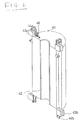
- Figs. 5 and 6 (these drawings show a face side and a back side of a cage 40, respectively), the cage 40 is formed into a shape of substantially semi-circular cross-section, in the face side of which a door 41 is mounted so as to be capable of opening and closing.
- permanent magnets 42 are mounted so as to oppose the linear motor primary coils 14a-14c and 15a-15c.
- a linear synchronous motor, so-called LSM comprises these linear motor primary coils 14a-14c, 15a-15c and permanent magnets 42.
- a linear induction motor, so-called LIM, etc. can also be used.
- Both upper and lower ends of the cage 40 are provided with upper guides 43a, upper guide rollers 44a and lower guides 43b, and lower guide rollers 44a, respectively, for being guided by the edges of the frames 11a-11c.
- a stopping device 45 comprising a pin 45a which engages with a recess 16a-16c by protruding at the time of stopping.
- a locking means comprises said stopping device 45 and recesses 16a-16c of frames 11a-11c.
- a current collector 46 is provided at the inside of one of the upper guides 43a.
- the pin 45a of the stopping device 45 protrudes so as to consequently fix the cage 40 to the frame 11a-11c by engaging with the recess 16a-16c.
Landscapes
- Engineering & Computer Science (AREA)
- Structural Engineering (AREA)
- Mechanical Engineering (AREA)
- Automation & Control Theory (AREA)
- Civil Engineering (AREA)
- Types And Forms Of Lifts (AREA)
- Lift-Guide Devices, And Elevator Ropes And Cables (AREA)
- Linear Motors (AREA)
Applications Claiming Priority (2)
| Application Number | Priority Date | Filing Date | Title |
|---|---|---|---|
| JP2207606A JPH0717333B2 (ja) | 1990-08-07 | 1990-08-07 | リニアモータ駆動エレベータ |
| JP207606/90 | 1990-08-07 |
Publications (3)
| Publication Number | Publication Date |
|---|---|
| EP0471464A2 true EP0471464A2 (de) | 1992-02-19 |
| EP0471464A3 EP0471464A3 (en) | 1992-05-27 |
| EP0471464B1 EP0471464B1 (de) | 1995-05-24 |
Family
ID=16542565
Family Applications (1)
| Application Number | Title | Priority Date | Filing Date |
|---|---|---|---|
| EP91306876A Expired - Lifetime EP0471464B1 (de) | 1990-08-07 | 1991-07-26 | Linearmotorangetriebener Aufzug |
Country Status (4)
| Country | Link |
|---|---|
| US (1) | US5235144A (de) |
| EP (1) | EP0471464B1 (de) |
| JP (1) | JPH0717333B2 (de) |
| DE (1) | DE69109968T2 (de) |
Cited By (12)
| Publication number | Priority date | Publication date | Assignee | Title |
|---|---|---|---|---|
| US5288956A (en) * | 1991-02-14 | 1994-02-22 | Kabushiki Kaisha Toshiba | Self running type elevator system using linear motors |
| WO2002002451A1 (de) * | 2000-07-01 | 2002-01-10 | Inventio Ag | Aufzug mit einem linearmotorantrieb |
| EP1113568A3 (de) * | 1999-12-30 | 2002-03-20 | Bison stematec, Maschinenbau- und Hubarbeitsbühnen Produktionsgesellschaft mbH | Verriegelungselement für elektomagnetische lineare Antriebsvorrichtungen |
| GB2402383A (en) * | 2003-06-02 | 2004-12-08 | Michael Godwin | Electromagnetic retarder for linear motor elevators |
| WO2010022907A1 (de) * | 2008-09-01 | 2010-03-04 | Thyssenkrupp Elevator Ag | Tragvorrichtung zum umsetzen eines fahrkorbs eines aufzugs |
| WO2012038760A3 (en) * | 2010-09-24 | 2012-08-09 | Adrian Michael Godwin | Transportation system |
| WO2014158127A1 (en) | 2013-03-25 | 2014-10-02 | Otis Elevator Company | Multicar self-propelled elevator system |
| CN104444713A (zh) * | 2014-12-15 | 2015-03-25 | 佛山市神风航空科技有限公司 | 一种小型旋转电梯 |
| WO2016118443A1 (en) * | 2015-01-21 | 2016-07-28 | Otis Elevator Company | Buffering device for multiple-car elevator system |
| EP3106418A1 (de) * | 2015-06-17 | 2016-12-21 | Kone Corporation | Lösung zum bewegen einer aufzugskabine |
| US20170073187A1 (en) * | 2015-09-14 | 2017-03-16 | Otis Elevator Company | Building management system integrated with elevator display |
| WO2018145864A3 (de) * | 2017-02-10 | 2018-10-11 | Thyssenkrupp Elevator Ag | Aufzuganlage mit mindestens zwei entlang eines gemeinsamen schienenstranges verfahrbaren fahrkörben |
Families Citing this family (27)
| Publication number | Priority date | Publication date | Assignee | Title |
|---|---|---|---|---|
| JP3278200B2 (ja) * | 1992-06-23 | 2002-04-30 | 三菱電機株式会社 | エレベータのデータ伝送装置 |
| US5419414A (en) * | 1993-11-18 | 1995-05-30 | Sakita; Masami | Elevator system with multiple cars in the same hoistway |
| US5569888A (en) * | 1994-05-26 | 1996-10-29 | Otis Elevator Company | Ultrasonic elevator door safety system |
| US5566784A (en) * | 1994-07-08 | 1996-10-22 | Otis Elevator Company | Self-propelled elevator system |
| US6085873A (en) * | 1999-05-27 | 2000-07-11 | Macchi; Anselmo John | Pneumatic elevator |
| US7019421B1 (en) | 2004-02-20 | 2006-03-28 | Curtiss-Wright Electro-Mechanical Corporation | Modular linear electric motor with limited stator excitation zone and stator gap compensation |
| JP4910385B2 (ja) * | 2005-12-16 | 2012-04-04 | ムラテックオートメーション株式会社 | 垂直搬送装置 |
| US7444919B1 (en) | 2006-08-29 | 2008-11-04 | The United States Of America As Represented By The Secretary Of The Navy | Tubular linear synchronous motor gun |
| US7917268B2 (en) * | 2007-04-16 | 2011-03-29 | Honda Motor Co., Ltd | Vehicle clutch engagement control system and method |
| KR101356111B1 (ko) | 2012-07-10 | 2014-01-28 | 정희섭 | 엘리베이터 장치 |
| KR101410342B1 (ko) * | 2012-08-20 | 2014-06-24 | 남 영 김 | 웜 구동부를 이용한 승강장치 |
| CN103145019B (zh) * | 2013-03-20 | 2015-07-08 | 中建三局集团有限公司 | 单塔多笼循环运行施工电梯 |
| KR101431719B1 (ko) * | 2013-04-05 | 2014-08-20 | 홍익대학교 산학협력단 | 경성 레일 코어 이용 이송 유닛 및 시스템 |
| KR101445225B1 (ko) * | 2013-04-05 | 2014-09-29 | 홍익대학교 산학협력단 | 경성 레일 코어 이용 다방향, 다중 이송 유닛 및 시스템 |
| HK1219469A1 (zh) * | 2013-05-21 | 2017-04-07 | Otis Elevator Company | 用於自推進電梯的無線電源 |
| DE102014104458A1 (de) * | 2014-03-28 | 2015-10-01 | Thyssenkrupp Elevator Ag | Aufzugsystem |
| CN104709785B (zh) * | 2015-03-20 | 2016-08-24 | 中建三局集团有限公司 | 智能群控调度及安全控制系统及实施方法 |
| CN104671037B (zh) * | 2015-03-20 | 2017-03-15 | 中建三局集团有限公司 | 智能旋转换轨控制系统及方法 |
| US10486940B2 (en) * | 2015-08-25 | 2019-11-26 | Otis Elevator Company | Alignment system for an elevator car |
| DE102015218025B4 (de) * | 2015-09-18 | 2019-12-12 | Thyssenkrupp Ag | Aufzugsystem |
| CN105398913B (zh) * | 2015-12-07 | 2018-01-16 | 中建三局集团有限公司 | 施工升降机导轨架传力转换盘及其制造方法 |
| EP3257802A1 (de) * | 2016-06-17 | 2017-12-20 | Siemens Aktiengesellschaft | Schachtförderanlage für den bergbau |
| DE102016211997A1 (de) * | 2016-07-01 | 2018-01-04 | Thyssenkrupp Ag | Aufzugsanlage |
| DE102017202405A1 (de) * | 2017-02-15 | 2018-08-16 | Thyssenkrupp Ag | Halteeinrichtung |
| ES2882640T3 (es) * | 2017-06-01 | 2021-12-02 | Kone Corp | Disposición y procedimiento para cambiar la dirección de movimiento de una cabina de un ascensor, y el ascensor correspondiente |
| EP3971122A1 (de) * | 2020-09-17 | 2022-03-23 | KONE Corporation | Aufzug |
| CN113734936A (zh) * | 2021-09-30 | 2021-12-03 | 广西桂华智能制造有限公司 | 圆周阵列分布的单个电梯井多个轿箱的电梯运行系统 |
Family Cites Families (10)
| Publication number | Priority date | Publication date | Assignee | Title |
|---|---|---|---|---|
| GB967985A (en) * | 1962-04-05 | 1964-08-26 | Morris Ltd Herbert | Improvements in cranes and lifts |
| US3317005A (en) * | 1965-04-21 | 1967-05-02 | Arthur H Kehoe | Elevator system |
| US3658155A (en) * | 1970-09-15 | 1972-04-25 | William G Salter | Elevator system |
| JPS4858542A (de) * | 1971-11-20 | 1973-08-16 | ||
| LU71614A1 (de) * | 1975-01-10 | 1976-11-11 | ||
| JPS5648385A (en) * | 1979-09-19 | 1981-05-01 | Itl Kk | Changing mechanism for separate lifting body in liftinggear |
| JPH01103671U (de) * | 1987-12-28 | 1989-07-13 | ||
| US4946006A (en) * | 1988-04-13 | 1990-08-07 | T. K. M. Engineering Kabushiki Kaisha | Elevator apparatus with a sectored vertical shaft and a turntable for transfering elevator cages between the individual sectors |
| JP2529756B2 (ja) * | 1990-06-11 | 1996-09-04 | 三菱電機株式会社 | リニアモ―タエレベ―タ― |
| US5090516A (en) * | 1991-03-15 | 1992-02-25 | Otis Elevator Company | Elevator linear motor bus bar |
-
1990
- 1990-08-07 JP JP2207606A patent/JPH0717333B2/ja not_active Expired - Lifetime
-
1991
- 1991-07-26 DE DE69109968T patent/DE69109968T2/de not_active Expired - Fee Related
- 1991-07-26 EP EP91306876A patent/EP0471464B1/de not_active Expired - Lifetime
- 1991-08-05 US US07/740,382 patent/US5235144A/en not_active Expired - Fee Related
Cited By (21)
| Publication number | Priority date | Publication date | Assignee | Title |
|---|---|---|---|---|
| US5288956A (en) * | 1991-02-14 | 1994-02-22 | Kabushiki Kaisha Toshiba | Self running type elevator system using linear motors |
| EP1113568A3 (de) * | 1999-12-30 | 2002-03-20 | Bison stematec, Maschinenbau- und Hubarbeitsbühnen Produktionsgesellschaft mbH | Verriegelungselement für elektomagnetische lineare Antriebsvorrichtungen |
| WO2002002451A1 (de) * | 2000-07-01 | 2002-01-10 | Inventio Ag | Aufzug mit einem linearmotorantrieb |
| GB2402383A (en) * | 2003-06-02 | 2004-12-08 | Michael Godwin | Electromagnetic retarder for linear motor elevators |
| US9016438B2 (en) | 2008-09-01 | 2015-04-28 | Thyssenkrupp Elevator Ag | Carrying device for relocating a car of an elevator |
| WO2010022907A1 (de) * | 2008-09-01 | 2010-03-04 | Thyssenkrupp Elevator Ag | Tragvorrichtung zum umsetzen eines fahrkorbs eines aufzugs |
| EP2161233A1 (de) | 2008-09-01 | 2010-03-10 | ThyssenKrupp Elevator AG | Tragvorrichtung zum Umsetzen eines Fahrkorbs eines Aufzugs |
| WO2012038760A3 (en) * | 2010-09-24 | 2012-08-09 | Adrian Michael Godwin | Transportation system |
| CN105246813A (zh) * | 2013-03-25 | 2016-01-13 | 奥的斯电梯公司 | 多轿厢自力推进电梯系统 |
| WO2014158127A1 (en) | 2013-03-25 | 2014-10-02 | Otis Elevator Company | Multicar self-propelled elevator system |
| EP2978703A4 (de) * | 2013-03-25 | 2016-11-02 | Otis Elevator Co | Selbstangetriebenes aufzugssystem mit mehreren fahrkörben |
| US10118799B2 (en) | 2013-03-25 | 2018-11-06 | Otis Elevator Company | Multicar self-propelled elevator system |
| CN105246813B (zh) * | 2013-03-25 | 2019-04-09 | 奥的斯电梯公司 | 多轿厢自力推进电梯系统 |
| CN104444713A (zh) * | 2014-12-15 | 2015-03-25 | 佛山市神风航空科技有限公司 | 一种小型旋转电梯 |
| WO2016118443A1 (en) * | 2015-01-21 | 2016-07-28 | Otis Elevator Company | Buffering device for multiple-car elevator system |
| CN107207204A (zh) * | 2015-01-21 | 2017-09-26 | 奥的斯电梯公司 | 用于多轿厢电梯系统的缓冲装置 |
| EP3106418A1 (de) * | 2015-06-17 | 2016-12-21 | Kone Corporation | Lösung zum bewegen einer aufzugskabine |
| US10781077B2 (en) | 2015-06-17 | 2020-09-22 | Kone Corporation | Solution for displacing an elevator car |
| US20170073187A1 (en) * | 2015-09-14 | 2017-03-16 | Otis Elevator Company | Building management system integrated with elevator display |
| US10029884B2 (en) * | 2015-09-14 | 2018-07-24 | Otis Elevator Company | Building management system integrated with elevator display |
| WO2018145864A3 (de) * | 2017-02-10 | 2018-10-11 | Thyssenkrupp Elevator Ag | Aufzuganlage mit mindestens zwei entlang eines gemeinsamen schienenstranges verfahrbaren fahrkörben |
Also Published As
| Publication number | Publication date |
|---|---|
| JPH0717333B2 (ja) | 1995-03-01 |
| EP0471464B1 (de) | 1995-05-24 |
| EP0471464A3 (en) | 1992-05-27 |
| DE69109968D1 (de) | 1995-06-29 |
| US5235144A (en) | 1993-08-10 |
| DE69109968T2 (de) | 1995-09-21 |
| JPH0494389A (ja) | 1992-03-26 |
Similar Documents
| Publication | Publication Date | Title |
|---|---|---|
| EP0471464B1 (de) | Linearmotorangetriebener Aufzug | |
| KR100424162B1 (ko) | 트랙션시브엘리베이터 | |
| US5566785A (en) | Elevator drive machine placed in the counterweight | |
| CA2113040C (en) | Elevator motor placed in the counterweight | |
| FI93632B (fi) | Alakoneistoinen vetopyörähissi | |
| CN103209919B (zh) | 一种升降装置及电梯系统 | |
| EP1127024B1 (de) | Treiberschaltung | |
| EP0630849B1 (de) | Aufzugsantriebsmaschine im Gegengewicht eingesetzt | |
| CA2471210C (en) | Lift installation, method of operating this lift installation and method of modernising a lift installation | |
| US5226507A (en) | Roping method of an elevator | |
| KR200272583Y1 (ko) | 주차설비의 승강기 구동장치 | |
| JPH02241352A (ja) | 円筒型リニアモータのエアギャップ調整装置 | |
| JPS63202579A (ja) | エレベ−タの更新工法 | |
| KR20120133686A (ko) | 웜 엘리베이터 순환시스템 | |
| JPH0348142Y2 (de) | ||
| FI93939B (fi) | Yläkoneistoinen vetopyörähissi | |
| JPS61235385A (ja) | エレベ−タ装置 | |
| KR19990027217A (ko) | 승강로의 피트 내에 권상기 및 제어반이 배치된 엘리베이터 | |
| JP2006256867A (ja) | エレベーター | |
| JP2000118912A (ja) | エレベーター装置 | |
| WO1999040013A1 (fr) | Dispositif de levage | |
| CN115701411A (zh) | 多轿厢电梯 | |
| JPH04164793A (ja) | ロープレスリニアモータエレベーター | |
| JP2004010212A (ja) | マシンルームレスエレベータ | |
| HK1033303B (en) | Preassembled elevator shaft |
Legal Events
| Date | Code | Title | Description |
|---|---|---|---|
| PUAI | Public reference made under article 153(3) epc to a published international application that has entered the european phase |
Free format text: ORIGINAL CODE: 0009012 |
|
| AK | Designated contracting states |
Kind code of ref document: A2 Designated state(s): DE FR GB |
|
| PUAL | Search report despatched |
Free format text: ORIGINAL CODE: 0009013 |
|
| AK | Designated contracting states |
Kind code of ref document: A3 Designated state(s): DE FR GB |
|
| 17P | Request for examination filed |
Effective date: 19920704 |
|
| 17Q | First examination report despatched |
Effective date: 19940707 |
|
| GRAA | (expected) grant |
Free format text: ORIGINAL CODE: 0009210 |
|
| AK | Designated contracting states |
Kind code of ref document: B1 Designated state(s): DE FR GB |
|
| REF | Corresponds to: |
Ref document number: 69109968 Country of ref document: DE Date of ref document: 19950629 |
|
| ET | Fr: translation filed | ||
| PLBE | No opposition filed within time limit |
Free format text: ORIGINAL CODE: 0009261 |
|
| STAA | Information on the status of an ep patent application or granted ep patent |
Free format text: STATUS: NO OPPOSITION FILED WITHIN TIME LIMIT |
|
| 26N | No opposition filed | ||
| PGFP | Annual fee paid to national office [announced via postgrant information from national office to epo] |
Ref country code: GB Payment date: 19980429 Year of fee payment: 8 Ref country code: FR Payment date: 19980429 Year of fee payment: 8 |
|
| PGFP | Annual fee paid to national office [announced via postgrant information from national office to epo] |
Ref country code: DE Payment date: 19980730 Year of fee payment: 8 |
|
| PG25 | Lapsed in a contracting state [announced via postgrant information from national office to epo] |
Ref country code: GB Free format text: LAPSE BECAUSE OF NON-PAYMENT OF DUE FEES Effective date: 19990726 |
|
| PG25 | Lapsed in a contracting state [announced via postgrant information from national office to epo] |
Ref country code: FR Free format text: THE PATENT HAS BEEN ANNULLED BY A DECISION OF A NATIONAL AUTHORITY Effective date: 19990731 |
|
| GBPC | Gb: european patent ceased through non-payment of renewal fee |
Effective date: 19990726 |
|
| PG25 | Lapsed in a contracting state [announced via postgrant information from national office to epo] |
Ref country code: DE Free format text: LAPSE BECAUSE OF NON-PAYMENT OF DUE FEES Effective date: 20000503 |
|
| REG | Reference to a national code |
Ref country code: FR Ref legal event code: ST |