EP0475558B1 - Verfahren und Gerät zur Eichung eines Systems für die Aufzeichnung und Ablesung von optisch feststellbaren Daten - Google Patents
Verfahren und Gerät zur Eichung eines Systems für die Aufzeichnung und Ablesung von optisch feststellbaren Daten Download PDFInfo
- Publication number
- EP0475558B1 EP0475558B1 EP91301692A EP91301692A EP0475558B1 EP 0475558 B1 EP0475558 B1 EP 0475558B1 EP 91301692 A EP91301692 A EP 91301692A EP 91301692 A EP91301692 A EP 91301692A EP 0475558 B1 EP0475558 B1 EP 0475558B1
- Authority
- EP
- European Patent Office
- Prior art keywords
- recording
- readback
- light
- data
- medium
- Prior art date
- Legal status (The legal status is an assumption and is not a legal conclusion. Google has not performed a legal analysis and makes no representation as to the accuracy of the status listed.)
- Expired - Lifetime
Links
- 238000012360 testing method Methods 0.000 claims description 53
- 230000003287 optical effect Effects 0.000 claims description 32
- 238000000034 method Methods 0.000 claims description 20
- 230000005855 radiation Effects 0.000 claims description 4
- 239000000463 material Substances 0.000 claims description 3
- 230000035945 sensitivity Effects 0.000 description 11
- 238000001514 detection method Methods 0.000 description 7
- 230000000694 effects Effects 0.000 description 7
- 238000004422 calculation algorithm Methods 0.000 description 5
- 230000008859 change Effects 0.000 description 5
- 238000012937 correction Methods 0.000 description 5
- 230000001965 increasing effect Effects 0.000 description 5
- 230000033001 locomotion Effects 0.000 description 5
- 230000003213 activating effect Effects 0.000 description 4
- 238000010586 diagram Methods 0.000 description 4
- 230000001360 synchronised effect Effects 0.000 description 4
- 230000006870 function Effects 0.000 description 3
- 238000010438 heat treatment Methods 0.000 description 3
- 239000000203 mixture Substances 0.000 description 3
- 230000009471 action Effects 0.000 description 2
- 230000015572 biosynthetic process Effects 0.000 description 2
- 239000003990 capacitor Substances 0.000 description 2
- 238000009792 diffusion process Methods 0.000 description 2
- 230000001976 improved effect Effects 0.000 description 2
- 108091008695 photoreceptors Proteins 0.000 description 2
- 230000008569 process Effects 0.000 description 2
- 230000009467 reduction Effects 0.000 description 2
- 238000003860 storage Methods 0.000 description 2
- 230000007704 transition Effects 0.000 description 2
- 230000005374 Kerr effect Effects 0.000 description 1
- 206010042618 Surgical procedure repeated Diseases 0.000 description 1
- 238000002679 ablation Methods 0.000 description 1
- 230000004308 accommodation Effects 0.000 description 1
- 238000004458 analytical method Methods 0.000 description 1
- 230000002457 bidirectional effect Effects 0.000 description 1
- 230000005540 biological transmission Effects 0.000 description 1
- 238000004364 calculation method Methods 0.000 description 1
- 239000011248 coating agent Substances 0.000 description 1
- 238000000576 coating method Methods 0.000 description 1
- 238000004891 communication Methods 0.000 description 1
- 238000004590 computer program Methods 0.000 description 1
- 239000013078 crystal Substances 0.000 description 1
- 230000001419 dependent effect Effects 0.000 description 1
- 238000009499 grossing Methods 0.000 description 1
- 230000001939 inductive effect Effects 0.000 description 1
- 230000000977 initiatory effect Effects 0.000 description 1
- 230000010354 integration Effects 0.000 description 1
- 238000004519 manufacturing process Methods 0.000 description 1
- 230000007246 mechanism Effects 0.000 description 1
- 238000002360 preparation method Methods 0.000 description 1
- 238000012545 processing Methods 0.000 description 1
- 229910000982 rare earth metal group alloy Inorganic materials 0.000 description 1
- 238000011084 recovery Methods 0.000 description 1
- 238000002310 reflectometry Methods 0.000 description 1
- 230000004043 responsiveness Effects 0.000 description 1
- 230000000630 rising effect Effects 0.000 description 1
- 238000010187 selection method Methods 0.000 description 1
- 239000004065 semiconductor Substances 0.000 description 1
- 238000000926 separation method Methods 0.000 description 1
- 230000036962 time dependent Effects 0.000 description 1
- 229910052723 transition metal Inorganic materials 0.000 description 1
- 150000003624 transition metals Chemical class 0.000 description 1
- 238000013316 zoning Methods 0.000 description 1
Images


Classifications
-
- G—PHYSICS
- G11—INFORMATION STORAGE
- G11B—INFORMATION STORAGE BASED ON RELATIVE MOVEMENT BETWEEN RECORD CARRIER AND TRANSDUCER
- G11B7/00—Recording or reproducing by optical means, e.g. recording using a thermal beam of optical radiation by modifying optical properties or the physical structure, reproducing using an optical beam at lower power by sensing optical properties; Record carriers therefor
- G11B7/12—Heads, e.g. forming of the optical beam spot or modulation of the optical beam
- G11B7/125—Optical beam sources therefor, e.g. laser control circuitry specially adapted for optical storage devices; Modulators, e.g. means for controlling the size or intensity of optical spots or optical traces
- G11B7/126—Circuits, methods or arrangements for laser control or stabilisation
-
- G—PHYSICS
- G11—INFORMATION STORAGE
- G11B—INFORMATION STORAGE BASED ON RELATIVE MOVEMENT BETWEEN RECORD CARRIER AND TRANSDUCER
- G11B11/00—Recording on or reproducing from the same record carrier wherein for these two operations the methods are covered by different main groups of groups G11B3/00 - G11B7/00 or by different subgroups of group G11B9/00; Record carriers therefor
- G11B11/10—Recording on or reproducing from the same record carrier wherein for these two operations the methods are covered by different main groups of groups G11B3/00 - G11B7/00 or by different subgroups of group G11B9/00; Record carriers therefor using recording by magnetic means or other means for magnetisation or demagnetisation of a record carrier, e.g. light induced spin magnetisation; Demagnetisation by thermal or stress means in the presence or not of an orienting magnetic field
- G11B11/105—Recording on or reproducing from the same record carrier wherein for these two operations the methods are covered by different main groups of groups G11B3/00 - G11B7/00 or by different subgroups of group G11B9/00; Record carriers therefor using recording by magnetic means or other means for magnetisation or demagnetisation of a record carrier, e.g. light induced spin magnetisation; Demagnetisation by thermal or stress means in the presence or not of an orienting magnetic field using a beam of light or a magnetic field for recording by change of magnetisation and a beam of light for reproducing, i.e. magneto-optical, e.g. light-induced thermomagnetic recording, spin magnetisation recording, Kerr or Faraday effect reproducing
- G11B11/10502—Recording on or reproducing from the same record carrier wherein for these two operations the methods are covered by different main groups of groups G11B3/00 - G11B7/00 or by different subgroups of group G11B9/00; Record carriers therefor using recording by magnetic means or other means for magnetisation or demagnetisation of a record carrier, e.g. light induced spin magnetisation; Demagnetisation by thermal or stress means in the presence or not of an orienting magnetic field using a beam of light or a magnetic field for recording by change of magnetisation and a beam of light for reproducing, i.e. magneto-optical, e.g. light-induced thermomagnetic recording, spin magnetisation recording, Kerr or Faraday effect reproducing characterised by the transducing operation to be executed
-
- G—PHYSICS
- G11—INFORMATION STORAGE
- G11B—INFORMATION STORAGE BASED ON RELATIVE MOVEMENT BETWEEN RECORD CARRIER AND TRANSDUCER
- G11B11/00—Recording on or reproducing from the same record carrier wherein for these two operations the methods are covered by different main groups of groups G11B3/00 - G11B7/00 or by different subgroups of group G11B9/00; Record carriers therefor
- G11B11/10—Recording on or reproducing from the same record carrier wherein for these two operations the methods are covered by different main groups of groups G11B3/00 - G11B7/00 or by different subgroups of group G11B9/00; Record carriers therefor using recording by magnetic means or other means for magnetisation or demagnetisation of a record carrier, e.g. light induced spin magnetisation; Demagnetisation by thermal or stress means in the presence or not of an orienting magnetic field
- G11B11/105—Recording on or reproducing from the same record carrier wherein for these two operations the methods are covered by different main groups of groups G11B3/00 - G11B7/00 or by different subgroups of group G11B9/00; Record carriers therefor using recording by magnetic means or other means for magnetisation or demagnetisation of a record carrier, e.g. light induced spin magnetisation; Demagnetisation by thermal or stress means in the presence or not of an orienting magnetic field using a beam of light or a magnetic field for recording by change of magnetisation and a beam of light for reproducing, i.e. magneto-optical, e.g. light-induced thermomagnetic recording, spin magnetisation recording, Kerr or Faraday effect reproducing
- G11B11/10595—Control of operating function
-
- G—PHYSICS
- G11—INFORMATION STORAGE
- G11B—INFORMATION STORAGE BASED ON RELATIVE MOVEMENT BETWEEN RECORD CARRIER AND TRANSDUCER
- G11B20/00—Signal processing not specific to the method of recording or reproducing; Circuits therefor
- G11B20/10—Digital recording or reproducing
- G11B20/18—Error detection or correction; Testing, e.g. of drop-outs
- G11B20/1816—Testing
- G11B20/182—Testing using test patterns
-
- G—PHYSICS
- G11—INFORMATION STORAGE
- G11B—INFORMATION STORAGE BASED ON RELATIVE MOVEMENT BETWEEN RECORD CARRIER AND TRANSDUCER
- G11B27/00—Editing; Indexing; Addressing; Timing or synchronising; Monitoring; Measuring tape travel
- G11B27/36—Monitoring, i.e. supervising the progress of recording or reproducing
-
- G—PHYSICS
- G11—INFORMATION STORAGE
- G11B—INFORMATION STORAGE BASED ON RELATIVE MOVEMENT BETWEEN RECORD CARRIER AND TRANSDUCER
- G11B7/00—Recording or reproducing by optical means, e.g. recording using a thermal beam of optical radiation by modifying optical properties or the physical structure, reproducing using an optical beam at lower power by sensing optical properties; Record carriers therefor
- G11B7/004—Recording, reproducing or erasing methods; Read, write or erase circuits therefor
- G11B7/0045—Recording
Definitions
- the present invention relates to systems for the recording and readback of optically detectable data which are commonly called optical disk recorders, and particularly to calibration of the light beams used in such systems.
- the invention is particularly useful for use with such systems using magneto-optic recording media.
- Some optical disk recorders employ constant lineal speed control, i.e., as the laser (light) beam scans radially more outward tracks, the rotational speed of the disk is reduced to maintain a constant lineal track scanning speed. Such recorders are often employed for audio and video recording.
- data recording devices such as those used with computers and the like, employ a constant rotational speed. It is to be appreciated that at a constant rotational speed a signal of a given duration is recorded as a longer mark in a radially-outermost track on the disk than when recorded on one of the radially-innermost tracks.
- PPM pulse-position-modulation
- pulse-width modulation provides for higher linear recording densities than PPM.
- pulse-width modulation the duration of a pulse recorded on a record track is varied for indicating different informational values. For example, a relatively short duration pulse would represent binary zero, a slightly longer pulse would represent a binary one, a yet longer pulse would represent a two, and so forth. A single recorded pulse could represent a number up to modulo 10 or 16. Pulse-width modulation greatly enhances the data storing capability of a record medium.
- Optical recording systems have used constant intensity laser (light) beams for creating recorded pulses on an optical medium. It is also well known that pulsed or "serrated" writing signals can also be applied. That is, a series of short duration pulses effectively record a single long pulse on the record medium. Thermal diffusion of the heat induced into the recording layer by the recording laser beam also causes distortion of the recorded pulse in optical recording. It is desired to minimise the negative effects of such thermal diffusions by carefully calibrating the laser write pulses to provide a uniformity of recording among a plurality of optical disk recorders.
- US-A-4,562,567 discloses an ablative optical recording system in which information is recorded in the form of optically-detectable, ahlative changes in the optical medium in the form of pits. As soon as the formation of a pit is initiated by ablation, the intensity of the laser beam is reduced for forming a more accurate pit. A change in the reflectivity of the optical. medium indicates the onset of pit formation. Such a luxury is not found in magneto-optic recording. Even with this type of control, there is no assurance that the accuracy of the pits is maintained from one type of optical medium to other types of optical medium. Therefore, it is still desired to provide for a laser calibration arrangement which ensures consistency among a plurality of optical recording media.
- EP-A-126,682 onto which the preambles of the independent claims are based shows recording a binary test word on an optical disk comprising a monotonous series of one and zero logic bits of equal duration. Then, reading those recorded words and measuring the duration in the bits in the one and the zero states provides for calibrating the recording laser to obtain ones and zero recordings of equal duration (pulse-width). The calibration is used to set the optical power of the laser to create one and zero recorded indices of equal circumferential duration. It is known that alternate ones and zeros are the highest recording frequency resulting in the shortest duration or spacing between successive transitions (this statement is true for NRZ or NRZI formats).
- test tracks are provided at the beginning and end of the disk (innermost- and outermost- radial tracks) for producing a correction factor for engraving (recording) power as a function of radius, i.e., the change in engraving power apparently is linear with radius.
- a correction factor for engraving (recording) power as a function of radius, i.e., the change in engraving power apparently is linear with radius.
- US-A-4,731,773 shows a magneto-optic recorder having a write control which tends to reduce unwanted radial enlargement of a recorded mark on a disk.
- the shape of the heat inducing pulse is altered from an initial high recording initiating value to a recording sustaining value such that the resulted recording in the track is of substantially uniform width along the length of the track being scanned.
- US-A-4,731,733 shows that the control reduces synchronous noise, i.e, second harmonic noise; yet greater correction and control of the writing process is required for successful high lineal density pulse-width-modulation recording.
- EP-A-45,117 shows an ablative recorder which adjusts the laser power for minimising second harmonic (synchronous noise) distortion in optical recording. While the reduction of synchronous noise is certainly important, the reduction of synchronous noise does not indicate any control of pulse duration necessary for effecting reliable pulse-width modulation and for high-density pulse-position modulation recording schemes for obtaining a maximal readback signal quality.
- EP-A-116,204 shows that a real-time feedback system adjusts the output power of the write laser or similar source for adjusting the modulation timing of write beam. This adjustment nulls out any unwanted DC component that is exhibited by the recorded data.
- the feedback is achieved by a read-after-write operation and stabilises the timing of the transitions in the recorded area.
- the unwanted DC component is an example of asymmetry occurring in recorded pulses. While this arrangement provides for accurate recording, it does require read-after-write capabilities, i.e., a multiple-beam head. Such a multiple-beam head adds to the cost of the recorder apparatus. It is desired to provide for precise recording either with a single-beam system or with a recorder such as that described in EP-A-116,204 which is initially set by a precise calibration technique.
- US-A-3,988,531 shows a system for compensating for pulse-length variations during readback. Such unintended length variations may give rise to duty factor errors.
- the compensating changes are made to the duty factor of the signal developed while reading the disk. These changes obviate spurious components attributable to duty factor error in image reproduction.
- the system described is an ablative system which employs ablated pits for indicating information with unablated areas constituting a spatial representation of a carrier signal frequency modulated by a band of video components. In the presence of duty factor error, the modulating component produces spurious counterparts in the baseband.
- a photoreceptor responds to the reading of the record track with a beam of energy to derive an output signal representative of the frequency modulated carrier.
- the output signals are further representative of the spurious component and have a phase and intensity indicative of the sense and extent of the duty factor error.
- the frequency selector derives the spurious component from the output of the photoreceptor.
- a compensator having means responsive to the derived output signal develops a first set of timing signals. Means responsive to the derived spurious component is included for selectively delaying alternate transitional portions of the drive output signal by an amount related to the amplitude of the spurious component for developing a series of adjusted width pulses.
- the means responds to the adjusted width pulses served to develop a second set of timing pulses.
- means are responsive to the first and second set of timing signals to provide for generating a signal having a duty factor corresponding to a desired duty factor. While a carrier signal is used in video recording, audio and data recording are always baseband recording without a carrier. Therefore, this solution to a change in duty factor is not usable in a data baseband recording environment, nor does it appear to provide a complete control of recorded pulses so as to enable high density pulse-position modulation (PPM) or pulse-width modulation (PWM).
- PPM pulse-position modulation
- PWM pulse-width modulation
- US-A-4,549,288 shows optical data recording apparatus which enhances a playback signal by comparing the lengths of the lands on a recording medium with the lengths of the pits. The playback signal is then changed to represent equality between such lengths. It is preferred to effect correction at the recording portion rather than relying on readback signal compensation techniques.
- the object of the present invention is to provide an improved method and apparatus for calibrating a system for recording and readback of optically detectable data.
- the present invention provides a method of calibrating a system for the recording and readback of optically detectable data of the type which comprises a record medium formed from a material which is sensitive to optical radiation, means for generating a beam of light, means for scanning said beam of light relative to the surface of said medium, means for selectively varying the intensity of said beam of light so as to record data at selected positions on said surface and means for reading back said recorded data, comprising the steps of: utilising said beam of light to record a plurality of test patterns on the surface of said medium each pattern being recorded with a different intensity of said beam of light, reading back said test patterns and generating a readback test signal characterised by measuring the amplitude of the readback test signal from each test pattern; detecting the readback test signal having the largest amplitude, and utilising the intensity of the beam of light used to record said test pattern which generates said readback test signal having the largest amplitude for said light beam when it is recording data.
- the invention also relates to apparatus for implementing the above method of calibrating.
- a large plurality of signals are recorded at the respective diverse laser (light beam) power levels and the readback of the recorded signals at each of the respective laser power levels are averaged.
- the average feedback signal amplitudes are then compared with a maximum average signal amplitude read back indicating which laser power level is to be used for subsequent recording.
- the envelope of the readback signal is used to indicate the amplitude of the readback signal. It is preferred that the test pattern represent the highest frequency components, i.e. the shortest one-half wavelengths, to be used in the ensuing recording.
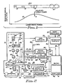
- curve 10 represents the relationship of readback signal amplitude with respect to laser write power in a system for recording and readback of optically detectable data.
- the laser write power increases from the left along the horizontal axis which results in the recording of spots 12-15 of various different sizes along a signal record track 30T. It has been determined that data signals should preferably be recorded using the laser power value which results in the readback signal amplitude as indicated by curve 10 reaching a maximum or near a maximum as indicated by vertical line 11.
- the quality of the readback signal is a strong function of the marks 12-15 recorded on an optical record medium, particularly a magneto-optic (MO) record medium.
- MO magneto-optic
- the recorded marks are too small, such as marks 12-13, the effective light reflected from the record medium results in a reduced readback signal amplitude.
- inter-symbol interference reduces the effective readback signal amplitude and also results in undesired peak shifting of the readback signal, which can cause signal detection errors.
- the size of marks 14 which result in a maximum readback signal amplitude and minimum peak shift.
- the signal to noise ratio reduces while jitter and peak shift increase, which reduces the probability of detecting the marks within a detection window as is known.
- the mark size is also a strong function of the signal storage medium sensitivity, the ambient temperature in which the medium resides, the recording pulse durations, spot size, laser power relative to the linear velocity of the medium as it passes by the recording laser beam and the amplitude of the magnetic bias or steering field used in magneto-optic recording. In other forms of recording, magnetic bias field is not used and is not a parameter.
- FIG. 2 An optical recorder with which the calibration system of the present invention may be advantageously employed is shown in Fig. 2.
- a magneto-optic record disk 30 is mounted for rotation on spindle 31 by motor 32.
- Optical head-carrying arm 33 on head-arm carriage generally denoted by numeral 34 moves radially of disk 30.
- a frame 35 of the recorder suitably mounts carriage 34 for reciprocating radial motions. The radial motions of carriage 34 enable access to any one of a plurality of concentric tracks or circumvolutions of a spiral track for recording data on and reading back data from disk 30.
- Linear actuator 36 suitably mounted on frame 35, radially moves carriage 34 for enabling track accessing.
- the recorder is suitably attached to one or more host processors 37.
- host processors may be control units, personal computers, large system computers, communication systems, image process processors, and the like.
- Attaching circuits 38 provide the logical and electrical connections between the optical recorder and the attaching host processors 37.
- Microprocessor 40 controls the recorder including the attachment to the host processor 37. Control data, status data, commands and the like are exchanged between attaching circuits 38 and microprocessor 40 via bidirectional bus 43. Included in microprocessor 40 is a program or microcode storing, read-only memory (ROM) 41 and a data and control signal storing random-access memory (RAM) 42. Microprocessor 40 controls the laser calibration, as will become apparent.
- ROM read-only memory
- RAM random-access memory
- the optical system of the recorder includes an objective or focusing lens 45 mounted for focusing and tracking motions on head arm 33 by fine actuator 46.
- This actuator includes mechanisms for moving lens 45 towards and away from disk 30 for focusing and for radial movements parallel to carriage 34 motions; for example, for changing tracks within a range of 100 tracks so that carriage 34 need not be moved each time a track adjacent to a track currently being accessed is to be accessed.
- Numeral 47 denotes a two-way light path between lens 45 and disk 30.
- magnet 48 in a constructed embodiment provides a weak magnetic steering or bias field for directing the remnant magnetisation direction of a small spot on disk 30 illuminated by laser light from lens 46.
- the laser light spot heats the illuminated spot on the record disk to a temperature above the Curie point of the magneto-optic layer (not shown, but can be an alloy of rare earth and transition metals as described in US-A-3,949,387). This heating enables magnet 48 to direct the remanant magnetisation to a desired direction of magnetisation as the spot cools below the Curie point temperature.
- Magnet 48 is shown as oriented in the "write” direction, i.e., binary ones are recorded on disk 30 normally by “north pole remanant magnetisation". To erase disk 30, magnet 48 reverses its magnetic field such that the south pole is adjacent disk 30.
- Magnet control 49 which is electrically coupled by line 50 to electromagnet 48, controls the write and erase directions of the electromagnet 48 produced magnetic steering field.
- Microprocessor 40 supplies control signals over line 51 to control 49 for effecting reversal of the recording direction.
- focus and tracking circuits 54 control both the coarse actuator 36 and fine actuator 46.
- the positioning of carriage 34 by actuator 36 is precisely controlled by control signals supplied by circuits 54 over line 55 to actuator 36.
- the actuator control by circuits 54 is exercised by control signals travelling over lines 57 and 58 respectively for focus and fine tracking and switching actions of fine actuator 46.
- Sensor 56 senses the relative position of fine actuator 46 to head arm carriage 33 and supplies a relative position signal over line 69.
- the focus and tracking position sensing is achieved by analysing laser light reflected from disk 30 over path 47, passed through lens 45, and through a first half-mirror 60 and then reflected by a second half-mirror 61 to a so-called "quad detector" 62.
- Quad detector 62 has four photo elements which supply signals respectively on four lines collectively denominated by number 63 to focus and tracking circuits 54. By aligning one axis of the detector 62 with a track centre line, track following operations are achieved. Focusing operations are achieved by comparing the light intensities detected by the four photo elements in the quad detector 62. Focus and tracking circuits 54 analyse the signals on lines 63 to control both focus and tracking.
- Microprocessor 40 supplies a control signal over line 65 to laser control 66 for indicating that a recording operation is to ensue.
- laser 67 is energised by control 66 to emit a high intensity laser light beam for recording; in contrast, for reading (readback), the laser 67 emitted laser light beam is at a reduced intensity for not heating the laser illuminated spot on disk 30 above the Curie point.
- Control 66 supplies its control signal over line 68 to laser 67.
- Data circuits 75 supply data or write pulses over line 78 to control 66 for modulating the operation of semiconductor laser 67 in a known manner.
- the laser 67 modulated light beam passes through polariser 70 (linearly polarising the beam), thence through collimating lens 71 towards half-mirror 60 for being reflected toward disk 30 through lens 45.
- Data circuits 75 are prepared for recording and the microprocessor 40 supplies suitable control signals over line 76.
- Microprocesscr 40 includes control circuits for effecting and controlling machine operations that occur too fast for being effected and controlled by micro-code execution.
- Microprocessor 40 in preparing circuits 75, is responding to commands for recording received from the host processor 37 via attaching circuits 38. Once data circuits 75 are prepared, data is transferred directly between host processor 37 and data circuits 75 through attaching circuit 38.
- Data circuits 75 also include ancillary circuits (not shown) for generating ancillary signals relating to disk 30 format signals, error detection and correction and the like. Circuits 75, during a read back or recovery action, strip the ancillary signals from the readback signals before supplying corrected data signals over bus 77 to host processor 37 via attaching circuits 38.
- Readback or recovering data from disk 30 for transmission to a host processor requires optical and electrical processing of the laser light beam for the disk 30.
- the portion of the reflected light (which has its linear polarisation from polariser 70 rotated by disk 30 recording using the Kerr effect) travels along the two-way light path 47, through lens 45 and half-mirrors 60 and 61 to the data detection portion 79 of the head arm 33 optical system.
- Half-mirror or beam splitter 80 divides the reflected beam into two equal intensity beams, both having the same reflected rotated linear polarisation.
- the half-mirror 80 reflected light travels through a first polariser 81 which is set to pass only that reflected light which has been rotated when the remnant magnetisation on disk 30 spot being accessed has a "north" or binary one indication. This passed light impinges on photo cell 82 for supplying a suitable indicating signal to differential amplifier 85.
- polariser 81 passes no or very little light resulting in no active signal being supplied by photocell 82.
- polariser 83 which passes only "south” rotated laser light beam to photo cell 84.
- Photo cell 84 supplies its signal indicating its received laser light to the second input of differential amplifier 85.
- the amplifier 85 supplies the resulting difference signals (data representing) to data circuits 75 for detection.
- the detected signals include not: only data that is recorded but also all of the so-called ancillary signals as well.
- the term "data” as used herein is intended to include any and all information-bearing signals, preferably of the digital or discrete value type.
- the rotational position and rotational speed of spindle 31 are sensed by a suitable tachometer or emitter sensor 90.
- Sensor 90 preferably of the optical rising type that senses dark and light spots on a tachometer wheel (not shown) of spindle 31, supplies the "tach" signals (digital signals) to rotational position sensing (RPS) circuit 91 which detects the rotational position of spindle 31 and supplies rotational information-bearing signals to microprocessor 40.
- Microprocessor 40 employs such rotational signals for controlling access to data storing segments on disk 30 as is widely practised in magnetic data storing disks. Additionally, the sensor 90 signals also travel to spindle speed control circuits 93 for controlling motor 32 to rotate spindle 31 at a constant rotational speed.
- Control circuits 93 may include a crystal controlled oscillator for controlling motor 32 speed, as is well known.
- Microprocessor 40 supplies control signals over lino 94 to control circuits 93 in the usual manner.
- the relationship between pulse-position modulation (PPM) data and the actual signal recorded on a magneto-optic medium illustrates some of the parameters of the operation of the calibration system of the present invention.
- the illustrated data shows two cycles of the pattern 1001 (highest density pattern) and two cycles of the pattern 100001 which can be represented as a minimum wavelength and a nominal wavelength of an encoded 2,7 D,K code.
- the resultant write pulses 100 show the different one-half wavelengths of the recording signal.
- spots 101 are recorded for each of the write pulses respectively. It is to be appreciated that the spots 101 are made circular and are idealised to that extent. When the spots are relatively close together, i.e.
- the readback signals 102 from each of the spots 101 interact to cause a readback signal portion 104 having reduced signal peak amplitudes.
- the spots 101 are spaced further apart, i.e. at the lower frequency data repetition rates, the isolated read signals 103 are spaced further apart with resultant less intersymbol interference (each mark 101 is considered a symbol).
- the readback signal portion 105 has increased signal amplitude.
- the intersymbol interference of the closely spaced marks 101 can also result in substantial peak shift of the peaks in the portion 104.
- the size of the recorded data marks 101 is affected by all of the parameters stated ahove with respect to Figure 1. An easy way to control the size of the marks 101 but optimise the size for the highest frequency of operation is through adjustment of laser power.
- FIG. 4 is a flowchart which illustrates the implementation the calibration system of the present invention in a constructed embodiment. This flowchart assumes that the focus of laser beam at path 47 has been achieved through the focusing of lens 45 as is known. A plurality of separate calibration tracks 29 are provided at a radially inward portion of disk 30. The initial description assumes that a calibration track has been selected.
- a first step is to high power erase the calibration track at machine step 110.
- a high power erase refers to an erasure in which there remains insubstantial residual recording; that is when a data track is erased, the power of any residual recording is less than the writing or recording laser power level. As a result, some residual remnant magnetisation may reside even after erasure, which is not a problem during normal recording.
- a test pattern is written.
- the highest frequency of data recording is represent by a three-bit pattern (100) where the binary 1 represents a write pulse and the binary 0's represents allowing the track to remain at the erasure direction.
- Successive (100) patterns cause a signal pattern as shown in Figure 3. It is desired to calibrate the laser at the highest frequency because of maximum intersymbol interference which reduces the amplitude of the readback signal as shown in Figure 3.
- the test pattern is written in step 111 on the second rotation of disk 30.
- the test pattern includes repetitions of the (100) pattern at a large plurality of different or diverse laser power levels which will become apparent.
- the just recorded test pattern on the calibration track is then read with the readback signal amplitude being envelope detected for measuring and indicating the readback signal amplitude for each of the respective laser power levels used during machine step 111.
- the reading (readback) step 112 effects separation of all different power level recordings such that the measured readback signal amplitude can be averaged in machine step 113.
- Machine step 113 is per formed within microprocessor 40 wherein all of the sample amplitudes sensed by machine step 112 and supplied to microprocessor 40 are used to calculate the mean for samples from the test patterns. Curve 10 of Figure 1 represents the results of such calculations.
- Microprocessor 40 can also use known curve smoothing algorithms for eliminating out of range data points and to perform a known curve fitting procedure to generate the curve 10.
- One curve fitting procedure found effective is a second order polynomial least square fitting algorithm.
- the calibration operation can be repeated by selecting another track at the radial midpoint of the recording area and then at the radially outer region of the recording area. Then the recording area can be zoned and different laser power levels can be determined for the radially inner tracks, the middle tracks and the radially outer tracks of the recording zone.
- the laser power can be adjusted linearly by using interpolation techniques for all of the tracks in between the radially inner, the middle and the radially outer calibration tracks. In many instances, calibrating at the radially inner tracks is sufficient.
- the selected write power can be a predetermined percentage of the measured write power, such as 95 percent.
- the back setting is done by a percentage of the indicated laser power level resulting in the maximum sent readback signal amplitude.
- microprocessor 40 selects the erase power to be 80 percent of the recording or write power selected in machine step 115. All of the above steps 110-116 assume operation at a selected calibration track.
- Magneto-optic media are subject to sensitivity shift with time (SST) which can cause variations in recording at the same recording laser power level.
- SST sensitivity shift with time
- the SST for a given record medium is dependent upon the composition of the magneto-optic layer as well as other manufacturing techniques used in making a record medium.
- the SST results in a reduced sensitivity to laser recording; i.e. a smaller mark 101 is generated for the same level after an SST has occurred for the magneto-optic medium.
- the SST is towards increased sensitivity wherein a larger mark 101 occurs in those areas being subject to SST. Therefore it is desirable to calibrate the laser on those tracks not subject to SST.
- SST usually shows up in those areas of a record medium which are repeatedly accessed for recording and erasure; i.e. subject to update in places such as the directory areas of a record medium.
- SST occurs after 10,000 magnetisation reversals, i.e. recordings and erasures.
- the rate of SST will also vary.
- the SST can occur in only one sector of a track because that one sector is repeatedly erased and rewritten. Which sectors are repeatedly erased and rewritten usually is not logged and therefore it is unknown without performing time consuming tests on such sectors.
- One way to avoid SST is to assign a predetermined number of calibration tracks such as tracks 29 in Figure 2. Then within the group of tracks, a track is randomly selected for reducing the effects of repeated calibrations causing SST. Random selection of a track at machine step 117 reduces such SST. Because calibration is so important the number of erasures and rewriting as performed in steps 110 and 111 is recorded as reference R in one of the sectors of the track 30T as seen in Figure 8.
- the first machine step 118 after randomly selecting the track at machine step 117 is to read sector R of track 30T and detect the number of reversals in that track.
- microprocessor 40 compares the number in sector R of the selected calibration track with a maximum permitted number of calibrations, such as 10,000. If the number R is less than 10,000, then steps 110-116 are performed within that randomly selected track. If the maximum number of calibrations in the randomly selected track exceeds the threshold such that SST may occur, then at machine step 119 microprocessor 40 causes the focus and tracking circuits 54 to move the fine actuator 46 to an adjacent calibration track where machine step 118 is repeated. This loop can reoccur until a calibration track is found which has less than the maximum number of calibrations performed. Instead of seeking to an adjacent track in machine step 119, another random selection may occur through microprocessor 40 microcode control. Such random track selection can be made by a program effecting random number selection.
- Figure 5 shows the generation of the write pattern.
- the calibration is initiated by microprocessor 40 causing the focus and tracking circuit 54 to move the beam of radiation to one of the calibration tracks in calibration track set 29.
- microprocessor 40 defines an activating signal over line 76C, which is one of the lines in cable 76 of Figure 2, to activate encoder 120.
- Encoder 120 when activated repeatedly supplies data pattern (100) over line 122 to AND circuit 121 which is enabled by the activating signal on line 76C.
- AND circuit 121 passes the repeatedly generated test pattern (100) over line 123 through OR circuit 124 to pulse shaper 126.
- Shaper 126 converts the data into write pulses 100, as shown in Figure 3.
- AND circuit 127 is enabled by a write enable signal on line 128, received from microprocessor 40, to pass the write pulses to line 78 which then travel to the laser control 66 ( Figure 2) while recording the repeated test pattern.
- each track on disk 30 is divided into sectors which are on radially extending lines equi-angularly spaced apart throughout the circumference of disk 30.
- each track is divided into 25 sectors.
- the sectors are separated in a hard sector disk using embossed indicia which indicate the sector number, track number, and the onset of data recording area.
- Microprocessor 40 indicates to RPS circuit 91 the location of the sector identifications, As well as the recording areas as is known in the disk art.
- Microprocessor 40 responds to RPS circuit 91 in a known manner for generating a record signal over line 128, which is also a portion of line 76 to data circuit 75. Therefore, the line 78 carried write pulses are timed through angular or rotational position sensing in the usual manner.
- Figure 6 is a part of control 66 for energising the laser 67.
- the recording pulse level is determined by microprocessor 40 by sending a number over cable 65A, a portion of line 65 of Figure 2, which indicates the desired laser recording power level.
- Digital to analog converter DAC 130 converts the number on cable 65A into an analog value.
- Amplifier 131 amplifies the analog value to a predetermined level on line 132.
- Modulator MOD 133 receives the write pulses over line 78 from the Figure 5 illustrated circuits. When the write pulses 100 are at a zero level, then modulator 133 is activated to divert the signals on line 132 through a current source switch from laser 67.
- modulator 133 supplies a minimum laser power activating signal over line 68 to laser 67 which is insufficient to cause a reversal of magnetisation in disk 30 as explained with respect to Figure 2.
- modulator 133 is activated by the write pulses to remove the current diversion and direct the current from amplifier 131 to laser 67 over line 68.
- This additional current drive to laser 67 causes it immediately to emit a higher power laser beam for heating the disk 30 in the impinging area of the laser beam above the Curie point for reversing the magnetisation of the disk 30 at that spot 101, as described with respect to Figure 2.
- the data to be recorded is supplied over line 125 by data circuit 75 in synchronism with the RPS circuits 91 indicating rotational position, all as known. The sequence of writing the patterns and the actual patterns resulting is later described with respect to Figure 8.
- Figure 7 illustrates the detection of the recorded test patterns and the resultant generation of indicated readback signal amplitude.
- Figure 7 illustrates the operation, in part, of machine step 112 ( Figure 4).
- the reflected light from disk 30 is split into two beams which impinge upon photodiodes 82 and 84 respectively, as best seen in Figure 2, rather than the separate connections to differential amplifier 85.
- diodes 82 and 84 are connected in cascade with the centre connection being an input to operational amplifier 140.
- Operational amplifier 140 outputs readback signals 104, 105 ( Figure 3) over line 141 to the usual data detection circuits which are located within data circuit 75.
- envelope detector 142 receives readback signals 104, 105 for generating an average signal amplitude as will become apparent.
- Envelope detector 142 includes amplifier 144, which supplies the readback signals through rectifier 145 to integrator capacitor 146. Integrator capacitor 146 in turn supplies the integrated or averaged value through amplifier 147 to analog to digital converter 148. Analog to digital converter 148 generates a numerical value for the amplitude which is supplied over cable 76E to microprocessor 40. In the constructed embodiment one level of laser write power was used to record the test pattern (100) in a given sector of the disk. Accordingly, when a sector is terminated, microprocessor 40 supplies a signal over line 76S for resetting ADC 148 and squelching integrator 146 as represented by switch 149, all in preparation for reading the next sector containing the test pattern.
- Microprocessor 40 samples the signals on cable 76E just before sending signals 76S. The operation just described is repeated for each sector of the calibration track or tracks such that microprocessor 40 creates a table of sensed readback signal amplitudes based upon signal envelope integration. Upon completion of the sensing step 112, microprocessor 40 will have a complete table of all sensed values for calculating the mean average value using the curve fitting algorithm described with respect to machine step 113.
- Track 30T is shown as one sequence of diverse laser powers in a single calibration track. It is to be understood that the sectors within track 30T all have the same circumferential length, the sectors being shown of different length to accommodate the symbology representing the signal levels within the respective sectors.
- Sector R which is located immediately adjacent to the usual index mark of the optical disk, contains the number of times a calibration has occurred on the track for indicating exposure to SST. Erasure step 110 erases all of the sectors except sector R.
- the laser power is determined by microprocessor 40 activating DAC 130. The value supplied over cable 65A to DAC 130 is incremented at each sector mark represented in Figure 8 by the vertical lines between the indicated sectors as between sectors R and L.
- the first recorded test pattern sequence is at a minimum laser 67 power level for recording indicated by the letter L in sector L.
- Each subsequently recorded sector in the track has an increased laser power level of a predetermined step size. Step size is determined empirically.
- each magneto-optic medium may have different sensitivities based upon differing compositions and the like and other factors. Sensitivity may also vary with the ambient temperature in which the disk resides. Generally, the empirical determination will find a minimum and maximum laser power level for use in laser power calibration for writing.
- the range of laser power varied from about 5 milliwatts to over 8 milliwatts.
- the steps of laser power variation from sector to sector were selected to be substantially less than 1 milliwatt, for example about one-fourth milliwatt.
- the numeral N in Figure 8 represents the size of the step, for example the minimum laser power such as 5 milliwatts was used to record the test pattern in sector L.
- the laser power level for recording the test pattern was 5.25 milliwatts, for example.
- sector L + 2N the laser power used was 5.5 milliwatts, for example. This linear increase occurs throughout track 30T until the maximum laser power M is reached, such as 8.7 milliwatts.
- the sectors contiguous with sector M have reduced laser power recording, such as M - N and M - 2N.
- the sensitivity of a magneto-optic medium may vary from one area of disk 30 to another area of disk 30; therefore, using a single iteration of laser recording power levels may be insufficient to find truly a good average for determining the mean laser power to be used for recording signals in ensuing recording.
- One procedure for achieving this variation is first to record the calibration track as indicated in Figure 8 for track 30T.
- the level L may be moved one quadrant or 90 degrees of the track, with the track being rerecorded as in steps 110 and 111 but circumferentially offset. This procedure can be repeated four times resulting in eight reversals of the magneto-optic coating of track 30T for one calibration.
- a preferred accommodation of variation of recording sensitivity in disk 30 is to provide a plurality of iterations of laser power variation within one recording as occurs in one of the selected tracks of calibration tracks 29.
- Numerals 160 show zone 1 through zone 4 for providing four iterations of laser power variations within one track before zoning of track 160 is useful, when the sensitivity variations are frequent.
- zones A and B were generated as in track 161 for providing two iterations of laser power variations.
- the laser power has varied from the minimum value L to the maximum value M in a linear sized set of steps for ease in calibrating the laser power level using linear techniques.
- the calibration tracks can be distributed between the radially innermost portion, a middle portion and the radially outermost portion with a track in each of the sets of calibration tracks being randomly selected and the calibration procedure repeated in each of the three sets of calibration tracks. It is preferred, of course, that the tracks be dedicated to calibration. Also included within the scope of the present invention is the idea that, when the disk is initially used, a first set of calibration tracks may be dedicated and all other tracks used for data.
- the data used tracks may be replaced as calibration tracks by a selection procedure which measures the usage of the respective tracks; that is, each sector of the disk may have a counter which counts the number of write accesses for indicating the sensitivity change or SST factor for all of the sectors. During off periods of operation all of the sectors can be read and from this it can be determined which tracks have the least usage and therefore have the least exposure to SST. Most tracks can then be assigned to the calibration tracks. Since it is preferred to use radially innermost tracks, then an allocation algorithm should be employed for preferring the radially outermost tracks as being tracks first allocated for data usage.
Landscapes
- Physics & Mathematics (AREA)
- Optics & Photonics (AREA)
- Engineering & Computer Science (AREA)
- Signal Processing (AREA)
- Optical Recording Or Reproduction (AREA)
- Optical Head (AREA)
Claims (10)
- Verfahren zur Kalibrierung eines Systems zur Aufzeichnung und Wiedergabe optisch lesbarer Daten, das ein Aufzeichnungsmedium (30) umfaßt, das aus einem Material hergestellt ist, das gegen optische Bestrahlung empfindlich ist; weiterhin umfaßt das Verfahren ein Mittel (67) zur Erzeugung eines Lichtstrahls (47), ein Mittel (33) zur Abtastung des genannten Lichtstrahls in bezug auf die Oberfläche des genannten Mediums, ein Mittel (75) zur selektiven Änderung der Intensität des genannten Lichtstrahls, so daß Daten an ausgewählten Positionen auf der genannten Oberfläche aufgezeichnet werden können, und ein Mittel (79) zur Wiedergabe der genannten aufgezeichneten Daten; bestehend aus folgenden Schritten:Verwendung des genannten Lichtstrahls zur Aufzeichnung einer Mehrzahl an Testmustern (29) auf der Oberfläche des genannten Mediums, wobei jedes Muster mit einer unterschiedlichen Intensität des genannten Lichtstrahls aufgezeichnet ist,Wiedergabe der genannten Testmuster und Erzeugung eines Wiedergabetestsignals, charakterisiert durchdie Messung der Amplitude des Wiedergabetestsignals jedes Testmusters;Feststellung des Wiedergabetestsignals mit der größten Amplitude, undVerwendung der Intensität des Lichtstrahls, der zur Aufzeichnung des genannten Testmusters verwendet wird, das das genannte Wiedergabetestsignal mit der größten Amplitude für den genannten Lichtstrahl erzeugt, wenn es gerade Daten aufzeichnet.
- Ein Verfahren gemäß Anspruch 1, dadurch charakterisiert, daß die genannten Testmuster in Sequenz aufgezeichnet und die zur Aufzeichnung aufeinanderfolgender Muster verwendeten Lichtstrahlintensitäten um einen bestimmten Wert variieren.
- Ein Verfahren gemäß allen vorherigen Ansprüchen, dadurch charakterisiert, daß sich die genannten Testmuster in verschiedenen Bereichen des genannten Mediums befinden.
- Ein Verfahren gemäß Anspruch 3, dadurch charakterisiert, daß das genannte Medium eine Platte ist und die genannten verschiedenen Bereiche des genannten Mediums, die die genannten Testmuster enthalten, radial auf der genannten Platte voneinander versetzt sind.
- Ein Verfahren gemäß Anspruch 4, dadurch charakterisiert, daß die genannten verschiedenen Bereiche auf der Grundlage der Häufigkeit der Verwendung zur Aufzeichnung von Daten ausgewählt werden.
- Eine Vorrichtung zur Kalibrierung eines Systems zur Aufzeichnung und Wiedergabe optisch lesbarer Daten, das ein Aufzeichnungsmedium (30) umfaßt, das aus einem Material hergestellt ist, das gegen optische Bestrahlung empfindlich ist; weiterhin umfaßt das Verfahren ein Mittel zur Erzeugung eines Lichtstrahls (47), ein Mittel (33) zur Abtastung des genannten Lichtstrahls in bezug auf die Oberfläche des genannten Mediums, ein Mittel (75) zur selektiven Änderung der Intensität des genannten Lichtstrahls, so daß Daten an ausgewählten Positionen auf der genannten Oberfläche aufgezeichnet werden können, und ein Mittel (79) zur Wiedergabe der genannten aufgezeichneten Daten;Mittel zur Verwendung des genannten Lichtstrahls zur Aufzeichnung einer Mehrzahl an Testmustern (29) auf der Oberfläche des genannten Mediums, wobei jedes Muster mit einer unterschiedlichen Intensität des genannten Lichtstrahls aufgezeichnet ist,Mittel zur Wiedergabe der genannten Testmuster und Erzeugung eines Wiedergabetestsignals anhand jedes Testmusters, charakterisiert durchein Mittel zur Messung der Amplitude des Wiedergabetestsignals jedes Testmusters;Mittel zur Feststellung des Wiedergabetestsignals mit der größten Amplitude, undMittel zur Verwendung der Intensität des Lichtstrahls, der zur Aufzeichnung des genannten Testmusters verwendet wird, das das genannte Wiedergabetestsignal mit der größten Amplitude für den genannten Lichtstrahl erzeugt, wenn es gerade Daten aufzeichnet.
- Eine Vorrichtung gemäß Anspruch 6, dadurch charakterisiert, daß die genannten Testmuster in Sequenz aufgezeichnet werden und die zur Aufzeichnung aufeinanderfolgender Testmuster verwendeten Lichtstrahlintensitäten um einen bestimmten Wert variieren.
- Eine Vorrichtung gemäß Anspruch 6 oder 7, dadurch charakterisiert, daß sich die genannten Testmuster in verschiedenen Bereichen des genannten Mediums befinden.
- Eine Vorrichtung gemäß Anspruch 8, dadurch charakterisiert, daß das genannte Medium eine Platte ist und die genannten verschiedenen Bereiche des genannten Mediums, die die genannten Testmuster enthalten, radial auf der genannten Platte voneinander versetzt sind.
- Eine Vorrichtung gemäß Anspruch 9, dadurch charakterisiert, daß die genannten verschiedenen Bereiche auf der Grundlage der Häufigkeit der Verwendung zur Aufzeichnung von Daten ausgewählt werden.
Applications Claiming Priority (2)
| Application Number | Priority Date | Filing Date | Title |
|---|---|---|---|
| US486480 | 1983-04-19 | ||
| US07/486,840 US5185733A (en) | 1990-03-01 | 1990-03-01 | Calibrating lasers for optical recording using a maximal readback signal amplitude as a criterion |
Publications (3)
| Publication Number | Publication Date |
|---|---|
| EP0475558A2 EP0475558A2 (de) | 1992-03-18 |
| EP0475558A3 EP0475558A3 (en) | 1992-11-25 |
| EP0475558B1 true EP0475558B1 (de) | 1996-01-03 |
Family
ID=23933433
Family Applications (1)
| Application Number | Title | Priority Date | Filing Date |
|---|---|---|---|
| EP91301692A Expired - Lifetime EP0475558B1 (de) | 1990-03-01 | 1991-03-01 | Verfahren und Gerät zur Eichung eines Systems für die Aufzeichnung und Ablesung von optisch feststellbaren Daten |
Country Status (5)
| Country | Link |
|---|---|
| US (1) | US5185733A (de) |
| EP (1) | EP0475558B1 (de) |
| JP (1) | JP2647269B2 (de) |
| CA (1) | CA2036958C (de) |
| DE (1) | DE69116039T2 (de) |
Cited By (1)
| Publication number | Priority date | Publication date | Assignee | Title |
|---|---|---|---|---|
| WO2018170232A1 (en) * | 2017-03-16 | 2018-09-20 | Symmetry Sensors, Inc. | Systems and methods for optical perception |
Families Citing this family (67)
| Publication number | Priority date | Publication date | Assignee | Title |
|---|---|---|---|---|
| JP3124720B2 (ja) * | 1995-04-14 | 2001-01-15 | 株式会社リコー | 情報記録再生方法、情報記録再生装置及び情報記録媒体 |
| US5513165A (en) * | 1990-06-29 | 1996-04-30 | Hitachi, Ltd. | Method for controlling the farm of a magnetic domain of a magneto-optical disk using pre-write testing |
| JP2653259B2 (ja) * | 1991-03-19 | 1997-09-17 | 松下電器産業株式会社 | 記録レーザ強度設定方法及びレーザ記録装置 |
| JP3050336B2 (ja) * | 1991-07-05 | 2000-06-12 | パイオニア株式会社 | 追記型光ディスクへの記録方法及び光ディスク記録装置 |
| JP2795567B2 (ja) * | 1991-11-25 | 1998-09-10 | シャープ株式会社 | 光磁気ディスク及び再生方法 |
| JP3039099B2 (ja) * | 1992-02-14 | 2000-05-08 | ソニー株式会社 | 光ディスク記録装置およびその方法 |
| US5392273A (en) * | 1992-02-28 | 1995-02-21 | Fujitsu Limited | Optical storage drive controller with predetermined light source drive values stored in non-volatile memory |
| EP0559391B1 (de) * | 1992-03-03 | 1998-06-03 | Canon Kabushiki Kaisha | Magneto-optisches Aufzeichnungs- und Wiedergabeverfahren und Gerät |
| US6529451B2 (en) * | 1992-10-05 | 2003-03-04 | Mitsubishi Denki Kabushiki Kaisha | Optical disk and optical disk drive device |
| US7548497B2 (en) * | 1992-10-05 | 2009-06-16 | Mitsubishi Denki Kabushiki Kaisha | Optical disk and optical disk drive device |
| JP3078686B2 (ja) * | 1992-10-05 | 2000-08-21 | 三菱電機株式会社 | 光ディスク、光ディスク駆動装置および光ディスクの書き込み読み出し方法 |
| JP3212415B2 (ja) * | 1993-04-26 | 2001-09-25 | 株式会社リコー | 光記録装置の制御方法 |
| JPH06314472A (ja) * | 1993-05-06 | 1994-11-08 | Sony Corp | ディスク記録媒体駆動装置の自己診断方法 |
| US5537381A (en) * | 1993-09-02 | 1996-07-16 | Sharp Kabushiki Kaisha | Test-writing recording control method and test-writing recording control apparatus and optical recording medium |
| JPH08509314A (ja) * | 1994-02-14 | 1996-10-01 | フィリップス エレクトロニクス ネムローゼ フェン ノートシャップ | 記録キャリヤに信号を記録する方法および記録装置 |
| US5430702A (en) * | 1994-02-16 | 1995-07-04 | International Business Machines Corporation | Calibration of readback threshold in an optical storage device |
| US5450383A (en) | 1994-05-26 | 1995-09-12 | International Business Machines Corporation | Monitoring and adjusting laser write power in an optical disk recorder using pulse-width modulated power level checking signals |
| USD371701S (en) | 1994-05-31 | 1996-07-16 | P988 Jolly | Desk |
| US5739969A (en) * | 1994-07-26 | 1998-04-14 | Inwave Technologies, Inc. | Digital data storage using predetermined increments of time wherein each increment represents a plurality of bits of information |
| US5602814A (en) * | 1994-10-06 | 1997-02-11 | International Business Machines Corporation | Calibration of write-once disks using a single disk sector |
| JPH08129753A (ja) * | 1994-10-31 | 1996-05-21 | Nec Corp | 光記録再生装置 |
| US5633747A (en) * | 1994-12-21 | 1997-05-27 | Tencor Instruments | Variable spot-size scanning apparatus |
| JP3492800B2 (ja) * | 1995-02-17 | 2004-02-03 | 富士通株式会社 | 光記録装置及び再生レーザパワー設定方法 |
| US5548572A (en) * | 1995-03-31 | 1996-08-20 | International Business Machines Corporation | Spare and calibration sector management for optical WORM media |
| JPH08297874A (ja) * | 1995-04-26 | 1996-11-12 | Nec Gumma Ltd | 光磁気ディスク装置 |
| US5586099A (en) * | 1995-05-22 | 1996-12-17 | International Business Machines Corporation | Optimized laser read power based upon scan speed of optical medium and erasure characteristics of the medium |
| US5555237A (en) * | 1995-05-30 | 1996-09-10 | International Business Machines Corporation | Contamination detection apparatus and method using write power calibration values |
| WO1997006530A1 (en) * | 1995-08-09 | 1997-02-20 | Hitachi, Ltd. | Optical disk device |
| DE19537405A1 (de) * | 1995-10-09 | 1997-04-10 | Leybold Ag | Vorrichtung zum Laserstrahlbelichten eines kreisscheibenförmigen Substrates |
| US5825724A (en) * | 1995-11-07 | 1998-10-20 | Nikon Corporation | Magneto-optical recording method using laser beam intensity setting based on playback signal |
| US5808972A (en) * | 1995-12-28 | 1998-09-15 | Nikon Corporation | Stabilized overwriteable optical recording method using laser beam intensity settings |
| US6052347A (en) * | 1996-02-23 | 2000-04-18 | Ricoh Company, Ltd. | Method and apparatus for detecting optimum recording power for an optical disk |
| US5617401A (en) * | 1996-03-08 | 1997-04-01 | International Business Machines Corporation | Calibration of lasers that produce multiple power output levels of emitted radiation |
| US5793737A (en) * | 1996-12-06 | 1998-08-11 | U.S. Philips Corporation | Method and apparatus for writing optical recording media with optimum value of write power |
| WO1998025266A1 (en) * | 1996-12-06 | 1998-06-11 | Koninklijke Philips Electronics N.V. | Optical recording medium |
| US6134209A (en) * | 1996-12-06 | 2000-10-17 | U.S. Philips Corporation | Producing optical recording using optimum write power |
| US7123563B2 (en) * | 1996-12-06 | 2006-10-17 | Koninklijke Philips Electronics N.V. | Optical recording method and apparatus using this method |
| RU2214629C2 (ru) * | 1996-12-24 | 2003-10-20 | Конинклейке Филипс Электроникс Н.В. | Способ оптической записи и устройство, использующее этот способ |
| EP0883113B1 (de) * | 1997-06-05 | 2009-06-03 | Panasonic Corporation | Optisches Plattengerät und Einstellverfahren für Steuerparameter |
| US6243339B1 (en) * | 1997-08-12 | 2001-06-05 | U.S. Philips Corporation | Method and device for writing optical record carriers |
| US6414912B1 (en) | 1998-02-04 | 2002-07-02 | Hitachi, Ltd. | Optical disk device using a recording medium structurally arranged to generate a recording clock |
| SG93198A1 (en) | 1998-04-20 | 2002-12-17 | Samsung Electronics Co Ltd | Recording medium for storing defect management information for recording real time data, defect managing method therefor, and real time data recording method |
| JP3765200B2 (ja) * | 1999-06-11 | 2006-04-12 | 株式会社リコー | 光ディスクのフォーマット方法とそれによりフォーマットされた光ディスク |
| JP2001134974A (ja) * | 1999-11-09 | 2001-05-18 | Sanyo Electric Co Ltd | 光ディスク記録再生装置のレーザー出力制御回路 |
| JP2001307326A (ja) * | 2000-04-20 | 2001-11-02 | Teac Corp | 光ディスク記録装置 |
| JP3765223B2 (ja) * | 2000-05-23 | 2006-04-12 | ヤマハ株式会社 | 光ディスク記録方法および光ディスク記録装置 |
| US6515693B1 (en) | 2000-06-29 | 2003-02-04 | Eastman Kodak Company | Calibration station for a printhead adapted to compensate for the wavelength sensitivity of an image recording material |
| JP2002117542A (ja) * | 2000-10-05 | 2002-04-19 | Pioneer Electronic Corp | 多層回転記録媒体及びその記録再生方法並びに記録再生装置 |
| PL209565B1 (pl) * | 2000-11-17 | 2011-09-30 | Koninkl Philips Electronics Nv | Sposób wyznaczania optymalnej wartości poziomu mocy zapisu wiązki promieniowania |
| EP1215907A3 (de) * | 2000-12-07 | 2006-04-26 | Sony United Kingdom Limited | Wasserzeichnung von Daten und Übertragung von wassergezeichneten Daten |
| JP3858605B2 (ja) * | 2001-02-13 | 2006-12-20 | ティアック株式会社 | 光ディスク記録装置及び光ディスク記録媒体 |
| WO2002075622A2 (en) * | 2001-03-20 | 2002-09-26 | Abraham Blau | System and method for item exchange |
| TWI270875B (en) | 2002-01-11 | 2007-01-11 | Via Tech Inc | A method for determining a writing power of a compact disc drive |
| JP4101666B2 (ja) * | 2002-01-22 | 2008-06-18 | 松下電器産業株式会社 | 情報記録媒体、記録装置、再生装置、記録方法、再生方法 |
| TWI254301B (en) * | 2002-04-05 | 2006-05-01 | Tdk Corp | Optical recording medium and method for optically recording information in the same |
| JP2004013938A (ja) * | 2002-06-03 | 2004-01-15 | Tdk Corp | レーザビーム強度決定方法及びこれを実行可能な情報記録装置並びに光記録媒体 |
| TW577060B (en) * | 2002-07-25 | 2004-02-21 | Mediatek Inc | Calibrating method of writing power for optical storage medium |
| US7514037B2 (en) * | 2002-08-08 | 2009-04-07 | Kobe Steel, Ltd. | AG base alloy thin film and sputtering target for forming AG base alloy thin film |
| JP4282285B2 (ja) * | 2002-08-12 | 2009-06-17 | Tdk株式会社 | 光記録媒体及び光記録方法 |
| US20040076907A1 (en) * | 2002-10-22 | 2004-04-22 | Tdk Corporation | Optical recording medium and method for manufacturing the same |
| EP1723645A2 (de) * | 2004-02-24 | 2006-11-22 | Koninklijke Philips Electronics N.V. | Aufzeichnungsvorrichtung mit einem medien- und temperaturabhängigen stromsteuerschema |
| US20050201235A1 (en) * | 2004-03-11 | 2005-09-15 | Samsung Electronics Co., Ltd. | Information storage medium capable of controlling optimal recording power, and method and apparatus for recording/reproducing data on the same |
| US7420580B2 (en) * | 2004-10-29 | 2008-09-02 | Hewlett-Packard Development Company, L.P. | Laser power calibration in an optical disc drive |
| US7701479B2 (en) * | 2004-12-17 | 2010-04-20 | Hewlett-Packard Development Company, L.P. | System and method for laser write power calibration |
| EP1831882B1 (de) * | 2004-12-23 | 2008-10-15 | Koninklijke Philips Electronics N.V. | Verfahren zur auswahl eines optimalen schreibparameters einer optischen aufzeichnungsvorrichtung |
| CN101192420B (zh) * | 2006-12-01 | 2010-09-29 | 鸿富锦精密工业(深圳)有限公司 | 刻录机及可读写碟片测试方法 |
| US20090048798A1 (en) * | 2007-08-15 | 2009-02-19 | Allen Keith Bates | Method for Performing Write Calibrations on Holographic Storage Media |
Family Cites Families (15)
| Publication number | Priority date | Publication date | Assignee | Title |
|---|---|---|---|---|
| US3988531A (en) * | 1975-04-02 | 1976-10-26 | Zenith Radio Corporation | System for compensating for incorrect duty factor when reading out information stored in a video disc |
| FR2358797A1 (fr) * | 1976-07-16 | 1978-02-10 | Thomson Brandt | Systeme de correction automatique du facteur de forme de l'onde porteuse issue de la lecture d'un support d'information |
| EP0005316A1 (de) * | 1978-03-27 | 1979-11-14 | Discovision Associates | Optisches Gerät und Verfahren zur Aufzeichnung von Information und mit diesem Gerät gebildeter Aufzeichnungsträger; optisches Gerät zum Auslesen der aufgezeichneten Information |
| JPS5880138A (ja) * | 1981-11-06 | 1983-05-14 | Teac Co | 光記録方式 |
| US4562567A (en) * | 1982-11-12 | 1985-12-31 | North American Philips Corporation | Apparatus for controlling the write beam in an optical data recording system |
| US4549288A (en) * | 1982-12-20 | 1985-10-22 | North American Philips Corporation | Apparatus for enhancing the playback signal in an optical data recording system |
| US4538257A (en) * | 1982-12-23 | 1985-08-27 | Xerox Corporation | Adaptively stabilized recording for direct read after write optical memories |
| FR2546325B1 (fr) * | 1983-05-20 | 1988-07-08 | Thomson Csf | Procede et dispositif de calibration de la puissance optique appliquee a un disque optique pour l'enregistrement de donnees |
| JP2605015B2 (ja) * | 1985-06-26 | 1997-04-30 | インターナショナル・ビジネス・マシーンズ・コーポレーション | 熱誘導記録の情報担特信号レコーダ |
| JPH0827950B2 (ja) * | 1986-10-20 | 1996-03-21 | オリンパス光学工業株式会社 | 光学的情報記録再生装置のレ−ザコントロ−ル回路 |
| JPS63117246A (ja) * | 1986-11-05 | 1988-05-21 | Matsushita Electric Ind Co Ltd | 書換型光デイスク検査装置 |
| EP0289004B1 (de) * | 1987-04-28 | 1994-03-23 | Sharp Kabushiki Kaisha | Aufzeichnungs- und Wiedergabegerät |
| JPH01102739A (ja) * | 1987-10-14 | 1989-04-20 | Brother Ind Ltd | 光ディスク装置 |
| JP2812441B2 (ja) * | 1988-10-11 | 1998-10-22 | キヤノン株式会社 | 光学的情報記録再生装置 |
| US5050156A (en) * | 1989-10-25 | 1991-09-17 | Eastman Kodak Company | Method and apparatus for calibrating the writing power applied to an optical media |
-
1990
- 1990-03-01 US US07/486,840 patent/US5185733A/en not_active Expired - Fee Related
-
1991
- 1991-02-01 JP JP3012204A patent/JP2647269B2/ja not_active Expired - Fee Related
- 1991-02-25 CA CA002036958A patent/CA2036958C/en not_active Expired - Fee Related
- 1991-03-01 EP EP91301692A patent/EP0475558B1/de not_active Expired - Lifetime
- 1991-03-01 DE DE69116039T patent/DE69116039T2/de not_active Expired - Fee Related
Cited By (1)
| Publication number | Priority date | Publication date | Assignee | Title |
|---|---|---|---|---|
| WO2018170232A1 (en) * | 2017-03-16 | 2018-09-20 | Symmetry Sensors, Inc. | Systems and methods for optical perception |
Also Published As
| Publication number | Publication date |
|---|---|
| JP2647269B2 (ja) | 1997-08-27 |
| CA2036958A1 (en) | 1991-09-02 |
| CA2036958C (en) | 1996-03-05 |
| EP0475558A2 (de) | 1992-03-18 |
| US5185733A (en) | 1993-02-09 |
| EP0475558A3 (en) | 1992-11-25 |
| JPH05189827A (ja) | 1993-07-30 |
| DE69116039D1 (de) | 1996-02-15 |
| DE69116039T2 (de) | 1996-07-04 |
Similar Documents
| Publication | Publication Date | Title |
|---|---|---|
| EP0475558B1 (de) | Verfahren und Gerät zur Eichung eines Systems für die Aufzeichnung und Ablesung von optisch feststellbaren Daten | |
| US5070495A (en) | Write calibration for magnetooptic disk recorders | |
| US5268893A (en) | Write power calibration utilizing least squares fit of read-back signals for moving media memory | |
| US5568461A (en) | Optical information recording and reproducing apparatus | |
| EP0144436B1 (de) | Optische aufzeichnungs- und wiedergabevorrichtung | |
| US5640381A (en) | Laser power-drive circuit having a scaling DAC supplying a scaled reference signal to a plurality of scaled DAC's that supply a plurality of scaled output signals | |
| JP2999684B2 (ja) | 光学ディスクの記録制御方法および光学ディスク装置 | |
| JP4075185B2 (ja) | 光学的情報記録再生方法及び光学的情報記録再生装置 | |
| EP0888614A1 (de) | Optisches aufzeichnungsmedium | |
| JP2804767B2 (ja) | 情報記録方法および装置並びに情報再生装置 | |
| EP0709842B1 (de) | Aufzeichnung und Wiedergabe von Daten | |
| JP3565886B2 (ja) | 記録担体上に信号を記録する方法及び記録装置 | |
| JP3850037B2 (ja) | 光記録担体の書込み方法及び装置 | |
| EP0904586B1 (de) | Optisches aufzeichnungsverfahren und -gerät | |
| US5648949A (en) | Method and apparatus for information reproduction at variable reference level | |
| EP0599389B1 (de) | Verfahren und Vorrichtung zur Aufzeichnung von Signalen auf einen Aufzeichnungsträger | |
| JPH08129753A (ja) | 光記録再生装置 | |
| JP3783264B2 (ja) | 情報再生方法及び情報再生装置 | |
| JP3231812B2 (ja) | 光ディスク装置 | |
| JP2937862B2 (ja) | 光磁気記録方法 | |
| JP2840685B2 (ja) | データ再生用クロック信号発生装置及びデータ再生装置 | |
| WO1998025266A1 (en) | Optical recording medium | |
| JPH02236839A (ja) | 光磁気記録再生装置 | |
| HK1013364B (en) | Method and recording device for recording signals on a record carrier |
Legal Events
| Date | Code | Title | Description |
|---|---|---|---|
| PUAI | Public reference made under article 153(3) epc to a published international application that has entered the european phase |
Free format text: ORIGINAL CODE: 0009012 |
|
| 17P | Request for examination filed |
Effective date: 19911219 |
|
| AK | Designated contracting states |
Kind code of ref document: A2 Designated state(s): DE FR GB IT |
|
| PUAL | Search report despatched |
Free format text: ORIGINAL CODE: 0009013 |
|
| AK | Designated contracting states |
Kind code of ref document: A3 Designated state(s): DE FR GB IT |
|
| 17Q | First examination report despatched |
Effective date: 19940720 |
|
| GRAA | (expected) grant |
Free format text: ORIGINAL CODE: 0009210 |
|
| AK | Designated contracting states |
Kind code of ref document: B1 Designated state(s): DE FR GB IT |
|
| REF | Corresponds to: |
Ref document number: 69116039 Country of ref document: DE Date of ref document: 19960215 |
|
| PGFP | Annual fee paid to national office [announced via postgrant information from national office to epo] |
Ref country code: FR Payment date: 19960307 Year of fee payment: 6 |
|
| ITF | It: translation for a ep patent filed | ||
| ET | Fr: translation filed | ||
| PLBE | No opposition filed within time limit |
Free format text: ORIGINAL CODE: 0009261 |
|
| STAA | Information on the status of an ep patent application or granted ep patent |
Free format text: STATUS: NO OPPOSITION FILED WITHIN TIME LIMIT |
|
| 26N | No opposition filed | ||
| PG25 | Lapsed in a contracting state [announced via postgrant information from national office to epo] |
Ref country code: FR Free format text: LAPSE BECAUSE OF NON-PAYMENT OF DUE FEES Effective date: 19971128 |
|
| REG | Reference to a national code |
Ref country code: FR Ref legal event code: ST |
|
| REG | Reference to a national code |
Ref country code: GB Ref legal event code: IF02 |
|
| PGFP | Annual fee paid to national office [announced via postgrant information from national office to epo] |
Ref country code: GB Payment date: 20040301 Year of fee payment: 14 |
|
| PGFP | Annual fee paid to national office [announced via postgrant information from national office to epo] |
Ref country code: DE Payment date: 20040322 Year of fee payment: 14 |
|
| PG25 | Lapsed in a contracting state [announced via postgrant information from national office to epo] |
Ref country code: IT Free format text: LAPSE BECAUSE OF NON-PAYMENT OF DUE FEES;WARNING: LAPSES OF ITALIAN PATENTS WITH EFFECTIVE DATE BEFORE 2007 MAY HAVE OCCURRED AT ANY TIME BEFORE 2007. THE CORRECT EFFECTIVE DATE MAY BE DIFFERENT FROM THE ONE RECORDED. Effective date: 20050301 Ref country code: GB Free format text: LAPSE BECAUSE OF NON-PAYMENT OF DUE FEES Effective date: 20050301 |
|
| PG25 | Lapsed in a contracting state [announced via postgrant information from national office to epo] |
Ref country code: DE Free format text: LAPSE BECAUSE OF NON-PAYMENT OF DUE FEES Effective date: 20051001 |
|
| GBPC | Gb: european patent ceased through non-payment of renewal fee |
Effective date: 20050301 |