EP0476809A2 - Grafisches Bildverarbeitungsgerät - Google Patents
Grafisches Bildverarbeitungsgerät Download PDFInfo
- Publication number
- EP0476809A2 EP0476809A2 EP91306465A EP91306465A EP0476809A2 EP 0476809 A2 EP0476809 A2 EP 0476809A2 EP 91306465 A EP91306465 A EP 91306465A EP 91306465 A EP91306465 A EP 91306465A EP 0476809 A2 EP0476809 A2 EP 0476809A2
- Authority
- EP
- European Patent Office
- Prior art keywords
- character pattern
- data
- shape
- selecting
- colour
- Prior art date
- Legal status (The legal status is an assumption and is not a legal conclusion. Google has not performed a legal analysis and makes no representation as to the accuracy of the status listed.)
- Granted
Links
Images


Classifications
-
- G—PHYSICS
- G06—COMPUTING OR CALCULATING; COUNTING
- G06F—ELECTRIC DIGITAL DATA PROCESSING
- G06F3/00—Input arrangements for transferring data to be processed into a form capable of being handled by the computer; Output arrangements for transferring data from processing unit to output unit, e.g. interface arrangements
- G06F3/01—Input arrangements or combined input and output arrangements for interaction between user and computer
- G06F3/02—Input arrangements using manually operated switches, e.g. using keyboards or dials
- G06F3/0202—Constructional details or processes of manufacture of the input device
- G06F3/0219—Special purpose keyboards
-
- A63F13/10—
-
- A—HUMAN NECESSITIES
- A63—SPORTS; GAMES; AMUSEMENTS
- A63F—CARD, BOARD, OR ROULETTE GAMES; INDOOR GAMES USING SMALL MOVING PLAYING BODIES; VIDEO GAMES; GAMES NOT OTHERWISE PROVIDED FOR
- A63F13/00—Video games, i.e. games using an electronically generated display having two or more dimensions
- A63F13/45—Controlling the progress of the video game
-
- G—PHYSICS
- G06—COMPUTING OR CALCULATING; COUNTING
- G06F—ELECTRIC DIGITAL DATA PROCESSING
- G06F3/00—Input arrangements for transferring data to be processed into a form capable of being handled by the computer; Output arrangements for transferring data from processing unit to output unit, e.g. interface arrangements
- G06F3/01—Input arrangements or combined input and output arrangements for interaction between user and computer
- G06F3/02—Input arrangements using manually operated switches, e.g. using keyboards or dials
- G06F3/0202—Constructional details or processes of manufacture of the input device
- G06F3/021—Arrangements integrating additional peripherals in a keyboard, e.g. card or barcode reader, optical scanner
- G06F3/0213—Arrangements providing an integrated pointing device in a keyboard, e.g. trackball, mini-joystick
-
- G—PHYSICS
- G06—COMPUTING OR CALCULATING; COUNTING
- G06F—ELECTRIC DIGITAL DATA PROCESSING
- G06F3/00—Input arrangements for transferring data to be processed into a form capable of being handled by the computer; Output arrangements for transferring data from processing unit to output unit, e.g. interface arrangements
- G06F3/01—Input arrangements or combined input and output arrangements for interaction between user and computer
- G06F3/048—Interaction techniques based on graphical user interfaces [GUI]
- G06F3/0484—Interaction techniques based on graphical user interfaces [GUI] for the control of specific functions or operations, e.g. selecting or manipulating an object, an image or a displayed text element, setting a parameter value or selecting a range
- G06F3/04845—Interaction techniques based on graphical user interfaces [GUI] for the control of specific functions or operations, e.g. selecting or manipulating an object, an image or a displayed text element, setting a parameter value or selecting a range for image manipulation, e.g. dragging, rotation, expansion or change of colour
-
- G—PHYSICS
- G06—COMPUTING OR CALCULATING; COUNTING
- G06F—ELECTRIC DIGITAL DATA PROCESSING
- G06F3/00—Input arrangements for transferring data to be processed into a form capable of being handled by the computer; Output arrangements for transferring data from processing unit to output unit, e.g. interface arrangements
- G06F3/01—Input arrangements or combined input and output arrangements for interaction between user and computer
- G06F3/048—Interaction techniques based on graphical user interfaces [GUI]
- G06F3/0487—Interaction techniques based on graphical user interfaces [GUI] using specific features provided by the input device, e.g. functions controlled by the rotation of a mouse with dual sensing arrangements, or of the nature of the input device, e.g. tap gestures based on pressure sensed by a digitiser
- G06F3/0489—Interaction techniques based on graphical user interfaces [GUI] using specific features provided by the input device, e.g. functions controlled by the rotation of a mouse with dual sensing arrangements, or of the nature of the input device, e.g. tap gestures based on pressure sensed by a digitiser using dedicated keyboard keys or combinations thereof
-
- G—PHYSICS
- G09—EDUCATION; CRYPTOGRAPHY; DISPLAY; ADVERTISING; SEALS
- G09B—EDUCATIONAL OR DEMONSTRATION APPLIANCES; APPLIANCES FOR TEACHING, OR COMMUNICATING WITH, THE BLIND, DEAF OR MUTE; MODELS; PLANETARIA; GLOBES; MAPS; DIAGRAMS
- G09B11/00—Teaching hand-writing, shorthand, drawing, or painting
- G09B11/10—Teaching painting
Definitions
- This invention relates to graphic image processing apparatus suitable for making a picture on the screen of a television receiver.
- Graphic image processing apparatus has been proposed for making a picture on a display screen of, for example, a television receiver or monitor.
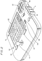
- This kind of graphic image processing apparatus includes a casing having a tablet and a key pad.
- the selected character pattern of the monitor is replaced by a cursor on the display screen of the monitor.
- the user can select a desired character pattern from several other character patterns newly displayed on the display screen by the character pattern selecting key or the like.
- the user can select the colour of the selected character pattern by a colour selecting key or the like, whereby the colour of the selected character pattern can be changed on the display screen of the monitor.
- the user moves the cursor to a desired position on the display screen of the monitor, by deciding the desired position of the cursor on the display screen of the monitor using a tablet pen on a tablet corresponding to the display screen of the monitor. Then, when the user pushes a position deciding key, the character pattern which has been replaced by the cursor can be placed at that desired position.
- the user since the user selects the desired character pattern from several character patterns displayed on the screen of the monitor by using the selecting key or the like, or the user selects the desired character pattern from several other character patterns additionally displayed on the screen of the monitor by the selecting key or the like, the user cannot look through all the character patterns available before selecting the desired character pattern. Thus, it is quite troublesome for the user to select a desired character pattern.
- the colour of the selected character pattern is selected by a colour selecting key or the like and decided after the user confirms the selected colour on the display screen of the monitor, the user cannot look through all the colours available, before selecting the desired colour of the character pattern. Also, therefore, it is quite troublesome for the user to select the colour of the character pattern. Furthermore, the selecting process of the character pattern and the selecting process of the colour of the selected character pattern is complicated, which results in a complicated process for making a picture.
- a graphic image processing apparatus comprising: character pattern selecting means for selecting a predetermined character pattern; colour selecting means for selecting predetermined colour data corresponding to said character pattern; display means for displaying said character pattern; operating means for moving a cursor on said display means; first memory means for storing data corresponding to said character pattern and colour information and reading them out; second memory means for storing display data which are displayed on said display means; control means for changing said cursor to said character pattern by operating said character pattern selecting means; and executing means for fixing said character pattern in said second memory means so as to display a desired position which is decided by the user by operating said operating means.
- a graphic image processing apparatus comprising: character pattern selecting keys for selecting predetermined character patterns; colour selecting keys for selecting predetermined colour data corresponding to said character patterns, said each key being formed on the same sheet switch plate, in which when said sheet switch plate is operated, analogue data corresponding to said character pattern are generated; operating means for moving a cursor on a connected displaying apparatus which is separated from said graphic image processing apparatus; an analogue-to-digital converter for converting said analogue data to digital data; a read only memory for storing digital data corresponding to said character patterns and said colour data and reading them out; a video processor for converting said digital data to video data so as to display said character pattern on said displaying apparatus; a random access memory for storing said video data; control means for replacing said cursor with said character pattern read out from said read only memory on a screen of said displaying apparatus by operating said character pattern selecting keys; executing means for fixing said character pattern in said random access memory so as to display a desired position which is decided by the user by operating said
- a graphic image processing apparatus for making a picture on a display screen, the apparatus comprising: memory means for storing a basic character and various characters corresponding to said basic character; memory control means for sequentially reading out said basic and various characters from said memory means so that the characters change on said screen like an animated motion; and a starting key for starting said animation.
- a graphic image processing apparatus comprising: character pattern selecting means for selecting a predetermined basic character pattern; display means for displaying said character pattern; operating means for moving a cursor on said display means; first memory means for storing data corresponding to a basic character and various characters corresponding to said basic character; second memory means for storing display data which are displayed on said display means; control means for changing said cursor to said character pattern by operating said character pattern selecting means; executing means for fixing said character pattern on said second memory means so as to display a desired position which is decided by the user by operating said operating means; memory control means for sequentially reading out said basic and various characters from said first memory means so that the characters change on a screen like an animated motion; and a starting key for starting said animation.
- a central processing unit (CPU) 1 is connected through a bus (formed of an address bus, control bus, data bus or the like) 2 to a read-only memory (ROM) 3 in which data such as programs, character patterns and so on are stored, and a RAM (random access memory) 4 in which data or the like can be stored.
- a video processor 5 sequentially reads image data which are stored in a RAM 6 through the bus 2 and the video processor 5, and converts them into R (red), G (green) and B (blue) signals. These R, G and B signals are supplied to an encoder (for example, an NTSC encoder) 7.
- the encoder 7 converts the R, G and B signals from the video processor 5 into an NTSC colour video signal, and this NTSC colour video signal is supplied to a monitor 8, thereby being displayed on the picture screen of the monitor 8 as image data.
- a sheet switch pad 20 comprises keys for designating character patterns displayed on the picture screen of the monitor and keys for specifying colours of character patterns selected by the character pattern designating keys, as will be described more fully later. If any of the keys on the sheet switch pad 20 is pushed, an analogue information signal generated by the depression of the key on the sheet switch pad 20 is converted into a digital information signal by an analogue-to-digital (A/D) converting circuit 21, and the digital information signal is supplied through a gate circuit 14 and the bus 2 to the CPU 1.
- a joystick 10 generates an analogue positional information signal from a potentiometer (not shown) provided at a right angle thereto.
- An analogue positional information signal from the joystick 10 is converted into a digital information signal by the A/D converting circuit 12 and fed through the gate circuit 14 and the bus 2 to the CPU 1.
- a slide volume 11 generates an analogue background colour information signal which changes the colour of a background of a picture when it is slidably moved.
- the analogue background colour information from the slide volume 11 is converted into a digital background colour information signal by the A/D converting circuit 12, and fed through the gate circuit 14 and the bus 2 to the CPU 1.
- a key switch pad 30 comprises a clear key 31, an undo key 32, an executing key 33, forward and backward designating keys 34r and 34f, an erase key 35, a GO/STOP key 36 and a scroll key unit 37 (see Figure 2).
- a command information signal output by the depression of any of the keys on the key switch pad 30 is supplied through an interface circuit 13, the gate circuit 14 and the bus 2 to the CPU 1.
- a buzzer 15 emits a sound associated with switch depression information or various command information supplied thereto from the CPU 1 through the gate circuit 14.
- the buzzer 15 is also arranged to emit an alarm sound every ten minutes until the next operation is carried out if no operation is carried out at all after the graphic image processing apparatus has been energized, so preventing power from being consumed uselessly.
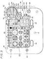
- FIGS 2 and 3 show the appearance of the embodiment of graphic image processing apparatus.
- the sheet switch pad 20 of Figure 2 comprises an abstract shape key unit 22, a colour designating key unit 21 and a specific shape key unit 23.
- the colour designating key unit 21 is used to designate the colour of the shape formed on the picture screen by the abstract shape key unit 22 and the specific shape key unit 23, both of which will be described more fully later.
- the colour designating key unit 21 comprises a white key 21w, a yellow key 21y, an orange key 21o, a red key 21r, a purple key 21p, a blue key 21b, a green key 21g and a black key 21bl, and the depression portions of the keys 21w, 21y, 21o, 21r, 21p, 21b, 21g and 21bl are coloured by colours of initial letters of the first digits thereof, respectively, so that the user can immediately understand the keys of colours to be used when he sees the keys.
- the abstract shape key unit 22 comprises 42 keys. When the user pushes any of these keys, the abstract shape shown on the pushed key can be displayed on the picture screen of the monitor 8.
- the specific shape key unit 23 comprises fourteen keys 23a, 23b, ..., 23n on which specific shapes are displayed, and specific shapes drawn on the keys 23a, 23b, ..., 23n are displayed on the picture screen by the depression thereof.
- the clear key 31 is used to clear the shape pattern displayed on the picture screen, and the undo key 32 is used to change the present state back to the previous state before a certain command was issued.
- the executing key 33 is used to determine the position of the shape selected by the specific shape key unit 23, and the forward and backward designating keys 34r and 34f are used to designate the front and back of the character pattern.
- the erase key 35 is used to erase the character pattern, and the GO/STOP key 36 is used to enable or disable the character pattern to move.
- the scroll key unit 37 is used to scroll the displayed shape pattern. As shown in Figure 3, the scroll key unit 37 comprises eight keys 37a, 37b, ..., 37i representing scroll conditions, respectively and the shape selected by the abstract shape key unit 22 or the specific shape key unit 23 is scrolled on the picture screen of the monitor 8 in accordance with the motion indicated by each of the scroll keys 37a, 37b, ..., 37i.
- Figure 3 shows a buzzer switch 38 which determines whether or not the buzzer 15 (see Figure 1) is energized, and a power switch 39.
- step 1000 whereat a demonstration occurs.
- a picture formed of an abstract shape or a specific shape is scrolled or moved on the picture screen of the monitor 8 in accordance with a demonstration pattern program stored beforehand in the ROM 3. Then, the processing proceeds to the next decision step 1100.
- step 1100 It is determined in decision step 1100 whether or not an arbitrary key (see Figure 2 or 3) has been pushed. If any key has been pushed as represented by a YES at decision step 1100, then the processing proceeds to step 1200, and if a NO is output at step 1100, then the processing returns to the step 1100 and the step 1100 is repeated. In step 1200, the cursor is initialized.
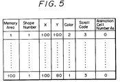
- a shape number indicative of a predetermined abstract shape for example, a circle
- positions X and Y coordinates of the ordinate and abscissa on the picture screen of the monitor 8
- colour data are stored in the memory area of, for example, the RAM 4 in accordance with the program stored beforehand in the ROM 3 as shown in Figure 5, and on the basis of data stored in the memory area of the RAM 4, a predetermined shape of predetermined colour data is stored in the RAM 6 at its predetermined position corresponding to the picture screen of the monitor 8 through the bus 2.
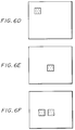
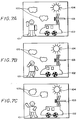
- the video processor 5 reads out data from the RAM 6, and the thus read image data are supplied through the encoder 7 to the monitor 8 so that an abstract shape of red-circle configuration is displayed by the cursor on the picture screen of the monitor 8 as shown in Figure 6A. Then, the processing proceeds to the next decision step 1300.
- step 1300 It is determined in decision step 1300 whether or not the joystick 10 (see Figure 3) is being operated. If the joystick 10 is being operated as represented by a YES at step 1300, then the processing proceeds to step 1400, whereas if a NO is output at step 1300, then the processing proceeds to the next decision step 1500.
- step 1400 data of positions X and Y (see Figure 5) of the memory area of the RAM 4 are changed in response to the digital positional information signal supplied to the CPU 1 from the joystick 10 through the A/D converting circuit 12, the gate circuit 14 and the bus 2, if necessary. Further, on the basis of these data, the shape corresponding to the shape number and stored in the ROM 3 is stored in the RAM 6 at its position (address) corresponding to the positions X and Y by colour data corresponding to the colour number if necessary.
- the shape corresponding to the shape number and stored in the ROM 3 is stored in the RAM 6 at its positions (addresses) corresponding the positions X and Y in the form of colour data corresponding to the colour number
- the shape corresponding to an animation cell number which will be described later, is stored in the RAM 6 at its positions (addresses) corresponding to the positions X and Y in the form of predetermined colour data.
- the video processor 5 reads the image data stored in the RAM 6 and the thus read image data are supplied through the encoder 7 to the monitor 8, so that the abstract shape formed of the cursor is displayed on the picture screen of the monitor 8 at its predetermined position as shown in Figure 6B. Then, the processing returns to decision step 1300 and the decision step 1300 is repeated.
- step 1500 It is determined in decision step 1500 whether or not the background colour button (slide volume) 11 is being operated. If the background colour button 11 is being operated as represented by a YES at step 1500, then the processing proceeds to step 1600. If on the other hand a NO is output at step 1500, then the processing proceeds to the next decision step 1700.
- step 1600 the portion other than the shape (that is, the background) is coloured in the designated colour on the picture screen of the monitor 8. That is, colour data of the designated background colour are stored in the RAM 6 at its address area corresponding to the background.
- the video processor 5 reads out data from the RAM 6 at its address area corresponding to the background and converts the thus read-out data into R, G and B signals on the basis of data such as the look-up table and information from the slide volume 11, thereby to change the background colour. Then, the processing returns to decision step 1300.
- decision step 1700 It is determined in decision step 1700 whether or not any key is being pushed. If a certain key is being pushed as represented by a YES at step 1700, then the processing proceeds to the next decision step 1800. If a NO is output at decision step 1700, then the decision step 1300 is repeated.
- the depression of an arbitrary key disables both the motion (animation motion) of the specific shape and the scroll of the abstract and specific shapes on the picture screen of the monitor 8.
- decision step 1800 It is determined in decision step 1800 whether or not the specific shape is moved like an animation motion and whether or not the specific and abstract shapes are scrolled. If a YES is output at step 1800, then the processing proceeds to step 1900, whereas if a NO is output at step 1800, then the processing proceeds to the next decision step 2000.
- step 1900 the motion (animation motion) of the specific shape and the scroll of the specific and abstract shapes are stopped, and then the processing proceeds to the next decision step 2000.
- decision step 2000 It is determined in decision step 2000 whether or not the executing key 33 is being pushed. If a YES is output at decision step 2000, then the processing proceeds to step 2100, whereas if a NO is output, then the processing proceeds to the next decision step 2200.
- step 2100 the processing is executed.
- the cursor represents a shape
- the shape formed of the cursor is determined at the cursor position. That is, as shown in Figure 5, data of the positions X and Y stored in the RAM 4 are determined, thereby one memory area being determined. Then, the processing returns to decision step 1300 and the decision step 1300 is repeated.
- decision step 2200 It is determined in decision step 2200 whether or not the colour designating key 21 is being pushed. If a YES is output at decision step 2200, then the processing proceeds to step 2300, whereas if a NO is output, then the processing proceeds to the next decision step 2400.
- step 2300 the colour of the cursor is changed. More specifically, as shown in Figure 5, the colour data of colour stored in the memory area of the RAM 4 are changed to colour data corresponding to the colour designated by the colour designating key unit 21, whereby the shape stored in the above memory area is stored in the RAM 6 by the colour data stored in the RAM 4. Then, the video processor 5 reads image data stored in the RAM 6, and the thus read image data are supplied through the encoder 7 to the monitor 8 so that the shape formed of the cursor is displayed on the picture screen of the monitor 8 in the colour designated by the colour designating key unit 21. In that event, while the specific shape is changed in position as the cursor, the colour of the specific chape cannot be changed by the colour designating key unit 21. As, for example, shown in Figure 6C, if the colour designating key 21g is pushed, then the colour of the abstract shape is changed to green, and then the processing returns to decision step 1300.
- decision step 2400 It is determined in decision step 2400 whether or not the abstract shape key 22 is being pushed. If a YES is output at decision step 2400, then the processing proceeds to step 2500, whereas if a NO is output, then the processing proceeds to the next decision step 2600.
- step 2500 the shape of the cursor is changed. That is, as shown in Figure 5, shape number data of the shape number stored in the memory area of the RAM 4 are changed to shape number data corresponding to the shape designated by the abstract shape key unit 22. Thus, shape data corresponding to the shape number data stored in the above RAM 4 are read out from the ROM 3 and the resultant shape data are stored in the RAM 6 on the basis of respective data of the above memory area. Then, the video processor 5 reads image data stored in the RAM 6 and the thus read image data are supplied through the encoder 7 to the monitor 8 so that the shape formed of the cursor is displayed on the picture screen of the monitor 8 in the form of the shape designated by the abstract shape key 22. As, for example, shown in Figure 6D, if the square mark key of the abstract shape key 22 is pushed, then the cursor of circle configuration is changed to the cursor of square configuration, and then the processing returns to decision step 1300 again.
- decision step 2600 It is determined in decision step 2600 whether or not the specific shape key unit 23 is being pushed. If a YES is output at decision step 2600, then the processing proceeds to step 2500, whereas if a NO is output, then the processing proceeds to the next decision step 2700.
- step 2500 the shape of the cursor is changed. More specifically, as shown in Figure 5, shape number data of shape number stored in the memory area of the RAM 4 are changed to shape number data corresponding to the shape designated by the specific shape key unit 23, whereby shape data corresponding to the shape number data stored in the RAM 4 are read out from the ROM 3.
- the thus read shape data are stored in the RAM 6 on the basis of each data stored in the above memory area.
- the video processor 5 reads the image data stored in the RAM 6 and the thus read image data are supplied through the encoder 7 to the monitor 8 so that the shape formed of the cursor is displayed on the picture screen of the monitor 8 in the form of the shape designated by the specific shape key 23.
- decision step 2700 It is determined in decision step 2700 whether or not the erase key 35 is being pushed. If a YES is output at decision step 2700, then the processing proceeds to step 2800, whereas if a NO is output, then the processing proceeds to the next decision step 2900. If the erase key 35 is being pushed, then the shape on the picture screen of the monitor 8 is erased by a hand-shaped area designating pointer P which will be described later and also all information of this shape are erased from the memory area of the RAM 4 shown in Figure 5.
- step 2800 the shape of the cursor is changed to the hand-shaped area designating pointer P shown in Figure 6G, and then the processing returns to decision step 1300 again.
- step 2900 It is determined at decision step 2900 whether or not the forward or backward key 34r or 34f is being pushed. If a YES is output at decision step 2900, then the processing proceeds to step 2800, whereat the shape of the cursor is changed to the hand-shaped area designating pointer P. If on the other hand a NO is output, then the processing proceeds to the next decision step 3000.
- step 3000 It is determined in decision step 3000 whether or not the scroll key unit 37 is being pushed. If a YES is output at decision step 3000, then the processing proceeds to step 2800, wherein the shape of the cursor is changed to the hand-shaped area designating pointer P. If a NO is output, then the processing proceeds to the next decision step 3100.
- decision step 3100 It is determined in decision step 3100 whether or not the clear key 31 is being pushed. If a YES is output at decision step 3100, then the processing proceeds to step 3200, whereat the clear processing is executed. If a NO is output, then the processing proceeds to the next decision step 3300.
- decision step 3300 It is determined in decision step 3300 whether or not the GO/STOP key 36 is being pushed. If a YES is output at decision step 3300, then the processing proceeds to step 3400, whereas if a NO is output, then the processing returns to decision step 1300 again.
- step 3400 the motion, that is, the scroll of the abstract or specific shape and the motion (animation motion) of the specific shape are started. If, for example, the abstract shape or specific shape is scrolled, then as shown by arrows displayed on the surfaces of the respective keys such as the scroll keys 37a, 37b, ..., 37i constituting the scroll key pad 37, the position of the shape is determined and then the abstract shape or specific shape designated by the area (shown in Figure 6H) designating pointer P is scrolled on the picture screen of the monitor 8. In this scrolling, as shown in Figure 5, the scroll code of the scroll codes stored in the memory area of the RAM 4 is changed in association with the pushed scroll key of the scroll key unit 37.
- data of the position X and Y are sequentially changed with a predetermined ratio, written in the RAM 6 as image data in accordance with the changed data stored in the memory area of the RAM 4 and sequentially read by the video processor 5.
- the thus read image data are supplied through the encoder 7 to the monitor 8, so the shape is scrolled as shown in Figure 6I.
- one point (formed of one dot) of the overlapping portion of more than two shapes or portion (formed of more than two dots) may be designated on the display screen of the monitor 8. If one point is designated, then the uppermost shape in the overlapping shapes is designated, whereas if the portion is designated, then the overlapping shapes are all designated.
- the abstract shape key unit 22 and specific shape key unit 23 which select a desired shape movable as the cursor until the shape is determined are arranged as the key which enables the user visually to confirm the shape of the shape.
- the colour designating key unit 21 which designates the colour of the shape selected by the above key unit 22 or 23 is arranged as the key which enables the user visually to confirm the kind of colours. Therefore, the shape can be selected and the colour of the shape can be selected immediately, thereby simplifying the process for creating the picture.
- the sheet switches on which the shape patterns and the colours are displayed are provided on one operating panel of this graphic image processing apparatus as shown in Figure 3, without displaying the shape on the picture screen of the monitor 8, the user can examine sufficiently the user's own idea for a picture such as shape, kind of shape and colour of shape and so on with reference to colours and shapes displayed on respective switches of the sheet switch pad 20.
- the response speed can be increased and the figure can be placed at the predetermined position on the picture screen of the monitor 8 with increased accuracy.
- the shape and the colour can be selected in that order or vice versa.
- the picture is displayed on the picture screen of the monitor 8
- the picture may be displayed on the display screen of a liquid crystal display (LCD) device.
- LCD liquid crystal display
- the desired character and the colour of the selected character can be selected very easily and comprehensively, which makes it possible for the user to draw a picture on the picture screen satisfactorily.
- a left hand of a man 101 is formed by the depression of the executing key 33 after the specific shape key 23f has been pushed; a right hand of the man 101 is formed by the depression of the executing key 33 after the specific shape key 23m has been pushed; a left leg of the man 101 is formed by the depression of the executing key 33 after the specific shape key 23g has been pushed; a right leg of the man is formed by the depression of the executing key 33 after the specific shape key 23n has been pushed; the head of the man 101 is formed by the depression of the executing key 33 after the specific key 23d has been pushed; clouds 105 are formed by the depression of the executing key 33 after the specific shape key 23h has been pushed; a circular light portion of the sun 104 is formed by the depression of the executing key 33 after the specific shape key 23a has been pushed; the eyes of a dragonfly 103 are formed by the depression of the executing key 33 after the specific
- the basic specific shapes determined by the depression of the executing key 33 after the specific shape key unit 23 has been pushed are stored beforehand in the ROM 3. More specifically, the cloud 105 is stored in a predetermined area of the ROM 3 in the form of a basic shape shown in Figure 8A; the wheel of the automobile 102 is stored in a predetermined area of the ROM 3 in the form of a basic shape shown in Figure 9A; the circular light portion of the sun 104 is stored in a predetermined area of the ROM 3 in the form of a basic shape shown in Figure 10A; the head of the man 101 is stored in a predetermined area of the ROM 3 in the form of a basic shape shown in Figure 11A; the right hand of the man 101 is stored in a predetermined area of the ROM 3 in the form of a basic shape shown in Figure 12A; the left hand of the man 101 is stored in a predetermined area of the ROM 3 in the form of a basic shape shown in Figure 13A; the left leg of the man 101 is
- Other basic specific shape data are stored in predetermined areas of the ROM 3 together with one of a plurality of specific shape data in which the basic specific shapes are changed similarly.
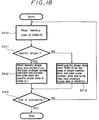
- decision step 3300 (corresponding to decision step 3300 in Figure 4) whether or not the GO/STOP key is being pushed. If a YES is output at decision step 3300, then the processing proceeds to step 3401, whereas if a NO is output, then the processing returns to step 3300 and step 3300 is repeated.
- step 3401 the memory area of the RAM 4 is read and then the processing proceeds to the next decision step 3402.
- decision step 3402 It is determined in decision step 3402 on the basis of the thus read shape number data of the shape number of the memory area of the RAM 4 whether or not the shape is the specific shape. If a YES is output at decision step 3402, then the processing proceeds to the next decision step 3403, whereas if a NO is output, then the processing proceeds to step 3406.
- step 3403 It is determined in decision step 3403 whether or not the animation cell number As is a maximum, or whether or not the animation cell number As is the sum of the number of a certain basic specific shape or the specific shapes in which a certain basic specific shape is changed. If a YES is output at decision step 3403, then the processing proceeds to step 3404, whereas if a NO is output, then the processing proceeds to step 3405.
- step 3404 the animation cell number As is set to zero.
- the animation cell number As is 0, data of the basic specific shape indicated by the shape number data of, for example, the shape number area are read out from the ROM 3, and then the processing proceeds to the next decision step 3406.
- step 3405 "1" is added to the animation cell number As, and the processing proceeds to the next decision step 3406.
- the animation cell number As is As + 1
- the data of a specific shape in which, for example, the basic specific shape designated by the shape number data of the shape number are changed are read out from the ROM 3.
- decision step 3406 It is determined in decision step 3406 whether or not an arbitrary key is pushed. If a YES is output at decision step 3406, then the processing proceeds to step 3407, whereas if a NO is output, then the processing returns to step 3401 again.
- step 3407 the re-writing of the animation cell number As is stopped when an arbitrary key is pushed, and then the processing is ended.
- step 3410 the memory area (see Figure 5) of the RAM 4 is read, and then the processing proceeds to the next decision step 3411.
- step 3411 It is determined in step 3411 on the basis of the shape number data of the shape number of the memory area read from the RAM 4 whether or not the shape is the specific shape. If a YES is output at decision step 3411, then the processing proceeds to step 3412, whereas if a NO is output, then the processing proceeds to step 3413.
- step 3414 On the basis of the shape number data of the shape number of the memory area of the RAM 4 and the animation cell number As, specific shape data (data of the basic specific shape or the specific shape in which the basic specific shape is changed) are read out from the ROM 3 and written in the RAM 6 of the video processor 5. Then, the processing proceeds to the next decision step 3414.
- step 3413 on the basis of the shape number data of shape number of the memory area of the RAM 4 and the colour code number data, abstract shape data are read out from the ROM 3 and the thus read abstract shape data are written in the RAM 6 of the video processor 5. Then, the processing proceeds to the next decision step 3414. It is determined in decision step 3414 whether or not the processing has ended. If a YES is output at decision step 3414, then the processing is ended, whereas if a NO is output, then the processing returns to step 3410.
- data of the specific shape in which the specific shape of the cloud 105 is further changed as shown in Figure 8C are written in the RAM 6 instead of the data of the specific shape of the cloud 105 shown in Figure 8B;
- data of the basic specific shape of the wheel of the automobile 102 shown in Figure 9A are written in the RAM 6 instead of the data of the specific shape of the wheel of the automobile 102 shown in Figure 9B;
- data of the basic specific shape of the circular light portion of the sun 104 shown in Figure 10A are written in the RAM 6 instead of the data of the specific shape of the circular light portion of the sun 104 shown in Figure 10B;
- data of the basic specific shape of the head of the man 101 shown in Figure 11A are written in the RAM 6 instead of the specific shape of the head of the man 101 shown in Figure 11B;
- data of specific shape in which the specific shape of the right hand of the man 101 are further changed as shown in Figure 12C are written in the RAM 6 instead of the data of the specific shape of the right hand of the man 101 shown in Figure 12B;
- an abstract shape may be moved in its own way or a picture formed by the combination of abstract shapes may be moved automatically in its own way.
- the basic shape data and the character pattern data in which the basic shape is changed are sequentially read out from the memory means when the start button is pushed and the basic shape and the character pattern of shape in which the basic shape is changed are sequentially displayed on the display screen of the display apparatus, the user can make a picture in a vivid fashion and the viewer can get satisfaction and pleasure in the pictures from a visual effect standpoint.
Landscapes
- Engineering & Computer Science (AREA)
- Theoretical Computer Science (AREA)
- General Engineering & Computer Science (AREA)
- Physics & Mathematics (AREA)
- General Physics & Mathematics (AREA)
- Human Computer Interaction (AREA)
- Multimedia (AREA)
- Business, Economics & Management (AREA)
- Educational Administration (AREA)
- Educational Technology (AREA)
- Processing Or Creating Images (AREA)
- Controls And Circuits For Display Device (AREA)
Applications Claiming Priority (4)
| Application Number | Priority Date | Filing Date | Title |
|---|---|---|---|
| JP2231883A JPH04112272A (ja) | 1990-08-31 | 1990-08-31 | 画像作成システム |
| JP231883/90 | 1990-08-31 | ||
| JP2242030A JPH04120669A (ja) | 1990-09-12 | 1990-09-12 | 画像作成システム |
| JP242030/90 | 1990-09-12 |
Publications (3)
| Publication Number | Publication Date |
|---|---|
| EP0476809A2 true EP0476809A2 (de) | 1992-03-25 |
| EP0476809A3 EP0476809A3 (en) | 1993-02-10 |
| EP0476809B1 EP0476809B1 (de) | 1997-10-15 |
Family
ID=26530163
Family Applications (1)
| Application Number | Title | Priority Date | Filing Date |
|---|---|---|---|
| EP91306465A Expired - Lifetime EP0476809B1 (de) | 1990-08-31 | 1991-07-16 | Grafisches Bildverarbeitungsgerät |
Country Status (5)
| Country | Link |
|---|---|
| US (1) | US5796388A (de) |
| EP (1) | EP0476809B1 (de) |
| AU (1) | AU644890B2 (de) |
| CA (1) | CA2046968C (de) |
| DE (1) | DE69127948T2 (de) |
Families Citing this family (28)
| Publication number | Priority date | Publication date | Assignee | Title |
|---|---|---|---|---|
| WO1996022580A1 (en) * | 1995-01-17 | 1996-07-25 | Sega Enterprises, Ltd. | Image processor and electronic apparatus |
| TW353171B (en) * | 1995-05-10 | 1999-02-21 | Nintendo Co Ltd | Manipulator provided with an analog joy stick |
| WO1997037295A1 (en) * | 1996-04-03 | 1997-10-09 | Philips Electronics N.V. | A hand-held control unit for controlling a display screen-oriented computer game, and a display screen-oriented computer game having one or more such control units |
| US6747681B1 (en) * | 1999-08-05 | 2004-06-08 | International Business Machines Corporation | Computer controlled interactive display with dual cursor image storage for a smooth transition during cursor image change |
| NO20004375L (no) * | 1999-12-06 | 2001-06-07 | Ziad Badarneh | System og fremgangsmåte for fremvisning og assistering av manipuleringsbevegelser ved betjening av en manöverinnretning foret funksjonsutstyr |
| USD757052S1 (en) * | 2000-01-04 | 2016-05-24 | Apple Inc. | Computer display screen with graphical user interface |
| GB2363504A (en) * | 2000-06-16 | 2001-12-19 | Nokia Mobile Phones Ltd | A mobile phone including a device for preventing loss or theft |
| USD479716S1 (en) | 2001-10-16 | 2003-09-16 | Mattel, Inc. | Hand-held electronic drawing device |
| USD491565S1 (en) | 2001-10-16 | 2004-06-15 | Mattel, Inc. | Cartridge for a hand-held electronic toy |
| USD532446S1 (en) * | 2004-02-05 | 2006-11-21 | Hewlett-Packard Development Company, L.P. | Device interface |
| US20060166592A1 (en) * | 2005-01-26 | 2006-07-27 | Nielsen Paul S | Electronic drawing toy |
| USD534205S1 (en) | 2005-07-14 | 2006-12-26 | Provo Craft And Novelty, Inc. | Electronic cutter |
| USD534204S1 (en) | 2005-07-14 | 2006-12-26 | Provo Craft And Novelty, Inc. | Electronic cutter |
| USD543583S1 (en) | 2005-07-14 | 2007-05-29 | Provo Craft And Novelty, Inc. | Electronic cutter |
| USD552621S1 (en) * | 2005-07-14 | 2007-10-09 | Brother Industries, Ltd. | Graphic user interface for handheld terminal |
| USD552619S1 (en) * | 2005-07-14 | 2007-10-09 | Brother Industries, Ltd. | Graphic user interface for handheld terminal |
| USD533897S1 (en) | 2005-07-14 | 2006-12-19 | Provo Craft And Novelty, Inc. | Electronic cutter |
| USD559855S1 (en) * | 2005-07-14 | 2008-01-15 | Brother Industries, Ltd. | Graphic user interface for handheld terminal |
| USD533582S1 (en) | 2005-07-14 | 2006-12-12 | Provo Craft And Novelty, Inc. | Control panel for an electronic cutter |
| KR101470413B1 (ko) * | 2007-09-20 | 2014-12-10 | 삼성전자주식회사 | 사용자 명령 입력 방법 및 이를 적용한 영상기기와입력기기 |
| US20100299710A1 (en) * | 2007-09-20 | 2010-11-25 | Samsung Electronics Co. Ltd. | Method for inputting user command and video apparatus and input apparatus employing the same |
| US8187051B2 (en) | 2007-10-26 | 2012-05-29 | Mattel, Inc. | Digital arts and crafts computer peripheral toy device |
| JP5760703B2 (ja) * | 2011-05-30 | 2015-08-12 | 株式会社リコー | 画像処理装置、画像処理プログラムおよび記録媒体 |
| USD748668S1 (en) * | 2012-11-23 | 2016-02-02 | Samsung Electronics Co., Ltd. | Display screen or portion thereof with transitional graphical user interface |
| USD769315S1 (en) * | 2015-07-09 | 2016-10-18 | Monthly Gift Inc. | Display screen or portion thereof with graphical user interface |
| USD815142S1 (en) * | 2016-04-04 | 2018-04-10 | The Raymond Corporation | Battery display screen or portion thereof with animated graphical user interface |
| USD916121S1 (en) | 2019-05-28 | 2021-04-13 | Apple Inc. | Display screen or portion thereof with graphical user interface |
| USD949182S1 (en) | 2020-05-27 | 2022-04-19 | Apple Inc. | Display screen or portion thereof with graphical user interface |
Family Cites Families (12)
| Publication number | Priority date | Publication date | Assignee | Title |
|---|---|---|---|---|
| DE1574606A1 (de) * | 1968-02-12 | 1971-06-16 | Siemens Ag | Verfahren zum Einlesen von Werkstueckdaten in eine elektronische Datenverarbeitungsanlage |
| US4045789A (en) * | 1975-10-29 | 1977-08-30 | Atari, Inc. | Animated video image display system and method |
| US4622641A (en) * | 1983-09-13 | 1986-11-11 | International Business Machines Corp. | Geometrical display generator |
| DE3420943A1 (de) * | 1984-06-05 | 1985-12-05 | Christoph Barth | Vorrichtung zur erstellung einer farbigen bildschirmtext-seite |
| US4709230A (en) * | 1985-04-19 | 1987-11-24 | Questron, Inc. | Color converter |
| US4764763A (en) * | 1985-12-13 | 1988-08-16 | The Ohio Art Company | Electronic sketching device |
| US4725694A (en) * | 1986-05-13 | 1988-02-16 | American Telephone And Telegraph Company, At&T Bell Laboratories | Computer interface device |
| JPS63127324A (ja) * | 1986-11-18 | 1988-05-31 | Hitachi Ltd | タツチパネル入力装置 |
| US4952051A (en) * | 1988-09-27 | 1990-08-28 | Lovell Douglas C | Method and apparatus for producing animated drawings and in-between drawings |
| US5088928A (en) * | 1988-11-15 | 1992-02-18 | Chan James K | Educational/board game apparatus |
| US4928093A (en) * | 1989-02-10 | 1990-05-22 | Hewlett-Packard Company | Cursor control mechanism |
| AU622823B2 (en) * | 1989-08-25 | 1992-04-16 | Sony Corporation | Portable graphic computer apparatus |
-
1991
- 1991-07-12 CA CA002046968A patent/CA2046968C/en not_active Expired - Fee Related
- 1991-07-16 EP EP91306465A patent/EP0476809B1/de not_active Expired - Lifetime
- 1991-07-16 DE DE69127948T patent/DE69127948T2/de not_active Expired - Fee Related
- 1991-07-18 AU AU81114/91A patent/AU644890B2/en not_active Ceased
-
1993
- 1993-03-11 US US08/031,036 patent/US5796388A/en not_active Expired - Fee Related
Also Published As
| Publication number | Publication date |
|---|---|
| CA2046968C (en) | 2001-04-10 |
| AU644890B2 (en) | 1993-12-23 |
| DE69127948T2 (de) | 1998-04-02 |
| AU8111491A (en) | 1992-03-05 |
| DE69127948D1 (de) | 1997-11-20 |
| US5796388A (en) | 1998-08-18 |
| CA2046968A1 (en) | 1992-03-01 |
| EP0476809B1 (de) | 1997-10-15 |
| EP0476809A3 (en) | 1993-02-10 |
Similar Documents
| Publication | Publication Date | Title |
|---|---|---|
| US5796388A (en) | Graphic image processing apparatus | |
| US5333255A (en) | Apparatus for displaying a plurality of two dimensional display regions on a display | |
| US5473740A (en) | Method and apparatus for interactively indicating image boundaries in digital image cropping | |
| KR100799054B1 (ko) | 데이터 입력 시스템 | |
| US6404420B1 (en) | Electronic device having a rotary switch and a display screen | |
| US5442378A (en) | Animation image constructing apparatus | |
| US6762749B1 (en) | Tactile interface system for electronic data display system | |
| KR950006579A (ko) | 아이콘 메뉴 표시장치 및 아이콘 메뉴 표시방법 | |
| US20040212626A1 (en) | System and a method for user interaction | |
| EP0836157A2 (de) | Informationsverarbeitungsgerät | |
| JP2006513486A (ja) | 表示スクリーンを有する手持型装置 | |
| EP0869474A3 (de) | Bildanzeigeeinrichtung mit Hinweiszeichen | |
| JPH07319616A (ja) | 位置入力方法およびそれを用いた会議支援システム | |
| KR100248450B1 (ko) | 화상작성시스템 | |
| EP0396358B1 (de) | Bildlesegerät | |
| JPS6313557Y2 (de) | ||
| KR960000820B1 (ko) | 화상작성장치 | |
| KR100248449B1 (ko) | 화상 작성 시스템 | |
| JPH04113475A (ja) | 画像作成システム | |
| JP3470407B2 (ja) | 表示文字色変更装置 | |
| KR950005535B1 (ko) | 화상작성 시스템에 있어서의 클리어 처리방법 | |
| JPH04118781A (ja) | 画像作成システム | |
| JP4683560B2 (ja) | 電子黒板システムにおける描画オブジェクトの隠蔽処理方法及び電子黒板システム | |
| JPH04120668A (ja) | 画像作成システム | |
| JPH08292834A (ja) | 描画装置 |
Legal Events
| Date | Code | Title | Description |
|---|---|---|---|
| PUAI | Public reference made under article 153(3) epc to a published international application that has entered the european phase |
Free format text: ORIGINAL CODE: 0009012 |
|
| AK | Designated contracting states |
Kind code of ref document: A2 Designated state(s): DE FR GB NL |
|
| PUAL | Search report despatched |
Free format text: ORIGINAL CODE: 0009013 |
|
| AK | Designated contracting states |
Kind code of ref document: A3 Designated state(s): DE FR GB NL |
|
| 17P | Request for examination filed |
Effective date: 19930626 |
|
| 17Q | First examination report despatched |
Effective date: 19960329 |
|
| GRAG | Despatch of communication of intention to grant |
Free format text: ORIGINAL CODE: EPIDOS AGRA |
|
| GRAG | Despatch of communication of intention to grant |
Free format text: ORIGINAL CODE: EPIDOS AGRA |
|
| GRAH | Despatch of communication of intention to grant a patent |
Free format text: ORIGINAL CODE: EPIDOS IGRA |
|
| GRAH | Despatch of communication of intention to grant a patent |
Free format text: ORIGINAL CODE: EPIDOS IGRA |
|
| GRAA | (expected) grant |
Free format text: ORIGINAL CODE: 0009210 |
|
| AK | Designated contracting states |
Kind code of ref document: B1 Designated state(s): DE FR GB NL |
|
| REF | Corresponds to: |
Ref document number: 69127948 Country of ref document: DE Date of ref document: 19971120 |
|
| ET | Fr: translation filed | ||
| PLBE | No opposition filed within time limit |
Free format text: ORIGINAL CODE: 0009261 |
|
| STAA | Information on the status of an ep patent application or granted ep patent |
Free format text: STATUS: NO OPPOSITION FILED WITHIN TIME LIMIT |
|
| 26N | No opposition filed | ||
| PGFP | Annual fee paid to national office [announced via postgrant information from national office to epo] |
Ref country code: DE Payment date: 20010709 Year of fee payment: 11 |
|
| PGFP | Annual fee paid to national office [announced via postgrant information from national office to epo] |
Ref country code: GB Payment date: 20010711 Year of fee payment: 11 |
|
| PGFP | Annual fee paid to national office [announced via postgrant information from national office to epo] |
Ref country code: FR Payment date: 20010712 Year of fee payment: 11 |
|
| PGFP | Annual fee paid to national office [announced via postgrant information from national office to epo] |
Ref country code: NL Payment date: 20010730 Year of fee payment: 11 |
|
| REG | Reference to a national code |
Ref country code: GB Ref legal event code: IF02 |
|
| PG25 | Lapsed in a contracting state [announced via postgrant information from national office to epo] |
Ref country code: GB Free format text: LAPSE BECAUSE OF NON-PAYMENT OF DUE FEES Effective date: 20020716 |
|
| PG25 | Lapsed in a contracting state [announced via postgrant information from national office to epo] |
Ref country code: NL Free format text: LAPSE BECAUSE OF NON-PAYMENT OF DUE FEES Effective date: 20030201 Ref country code: DE Free format text: LAPSE BECAUSE OF NON-PAYMENT OF DUE FEES Effective date: 20030201 |
|
| GBPC | Gb: european patent ceased through non-payment of renewal fee |
Effective date: 20020716 |
|
| PG25 | Lapsed in a contracting state [announced via postgrant information from national office to epo] |
Ref country code: FR Free format text: LAPSE BECAUSE OF NON-PAYMENT OF DUE FEES Effective date: 20030331 |
|
| NLV4 | Nl: lapsed or anulled due to non-payment of the annual fee |
Effective date: 20030201 |
|
| REG | Reference to a national code |
Ref country code: FR Ref legal event code: ST |