EP0478200B1 - Optische Platteneinheit - Google Patents
Optische Platteneinheit Download PDFInfo
- Publication number
- EP0478200B1 EP0478200B1 EP91308428A EP91308428A EP0478200B1 EP 0478200 B1 EP0478200 B1 EP 0478200B1 EP 91308428 A EP91308428 A EP 91308428A EP 91308428 A EP91308428 A EP 91308428A EP 0478200 B1 EP0478200 B1 EP 0478200B1
- Authority
- EP
- European Patent Office
- Prior art keywords
- optical disk
- velocity
- seek
- laser beam
- track
- Prior art date
- Legal status (The legal status is an assumption and is not a legal conclusion. Google has not performed a legal analysis and makes no representation as to the accuracy of the status listed.)
- Expired - Lifetime
Links
- 230000003287 optical effect Effects 0.000 title claims description 35
- 230000003247 decreasing effect Effects 0.000 claims description 7
- 230000035945 sensitivity Effects 0.000 claims description 7
- 230000007423 decrease Effects 0.000 claims description 5
- 238000011084 recovery Methods 0.000 claims description 2
- 230000000694 effects Effects 0.000 description 4
- 238000001914 filtration Methods 0.000 description 2
- 238000001514 detection method Methods 0.000 description 1
- 238000010586 diagram Methods 0.000 description 1
- 230000007935 neutral effect Effects 0.000 description 1
Images

Classifications
-
- G—PHYSICS
- G11—INFORMATION STORAGE
- G11B—INFORMATION STORAGE BASED ON RELATIVE MOVEMENT BETWEEN RECORD CARRIER AND TRANSDUCER
- G11B7/00—Recording or reproducing by optical means, e.g. recording using a thermal beam of optical radiation by modifying optical properties or the physical structure, reproducing using an optical beam at lower power by sensing optical properties; Record carriers therefor
- G11B7/08—Disposition or mounting of heads or light sources relatively to record carriers
- G11B7/085—Disposition or mounting of heads or light sources relatively to record carriers with provision for moving the light beam into, or out of, its operative position or across tracks, otherwise than during the transducing operation, e.g. for adjustment or preliminary positioning or track change or selection
- G11B7/08505—Methods for track change, selection or preliminary positioning by moving the head
- G11B7/08529—Methods and circuits to control the velocity of the head as it traverses the tracks
-
- G—PHYSICS
- G11—INFORMATION STORAGE
- G11B—INFORMATION STORAGE BASED ON RELATIVE MOVEMENT BETWEEN RECORD CARRIER AND TRANSDUCER
- G11B7/00—Recording or reproducing by optical means, e.g. recording using a thermal beam of optical radiation by modifying optical properties or the physical structure, reproducing using an optical beam at lower power by sensing optical properties; Record carriers therefor
- G11B7/08—Disposition or mounting of heads or light sources relatively to record carriers
- G11B7/085—Disposition or mounting of heads or light sources relatively to record carriers with provision for moving the light beam into, or out of, its operative position or across tracks, otherwise than during the transducing operation, e.g. for adjustment or preliminary positioning or track change or selection
- G11B7/08505—Methods for track change, selection or preliminary positioning by moving the head
- G11B7/08511—Methods for track change, selection or preliminary positioning by moving the head with focus pull-in only
-
- G—PHYSICS
- G11—INFORMATION STORAGE
- G11B—INFORMATION STORAGE BASED ON RELATIVE MOVEMENT BETWEEN RECORD CARRIER AND TRANSDUCER
- G11B7/00—Recording or reproducing by optical means, e.g. recording using a thermal beam of optical radiation by modifying optical properties or the physical structure, reproducing using an optical beam at lower power by sensing optical properties; Record carriers therefor
- G11B7/08—Disposition or mounting of heads or light sources relatively to record carriers
- G11B7/09—Disposition or mounting of heads or light sources relatively to record carriers with provision for moving the light beam or focus plane for the purpose of maintaining alignment of the light beam relative to the record carrier during transducing operation, e.g. to compensate for surface irregularities of the latter or for track following
- G11B7/0941—Methods and circuits for servo gain or phase compensation during operation
Definitions
- This invention relates to optical disk drive apparatus, and more particularly, to an apparatus used for controlling the focusing servo of an optical disk drive apparatus.
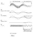
- FIG.5(A) shows a waveform of a Focus Error Signal (FES) obtained under the condition that the gain of a focus servo loop does not change during a seek operation.
- FES Focus Error Signal
- FIG.5(B) shows the swing of a disk surface during a seek operation
- FIG.5(C) shows the position of a lens, that is, the movement of the lens in the focusing direction during the seek operation.
- the movement of the lens follows the swing of the disk surface during a period of high seek velocity, but during a period of low seek velocity the movement of the lens is unable to follow the swing of disk surface due to the effect of scattering based on the track groove, as shown above.
- FIG.5(D) shows a defocusing condition during low seek velocity.
- FIG.5(E) shows a TES obtained during a seek operation.
- the TES has a constant amplitude during a period of high seek velocity, but has a low amplitude when defocusing occurs during a period of low seek velocity. Since the seek operation is controlled by positional information provided by the TES, the seek operation becomes out of control if the amplitude of the TES becomes low, and a target track cannot be reached.
- FIG.6(A) to FIG.6(E) relate to FIG.5(A) to FIG.5(E), but show values obtained when the control gain is lowered.
- Unstable amplitudes of the FES shown in FIG.6(A) indicate that a defocusing condition occurs as shown in FIG.6(D) and the amplitudes of the FES decrease according to the defocusing condition. As shown in FIG.6(E), such defocusing conditions cause the TES to vary, track count errors to occur frequently, and the seek operation to be out of control.
- An object of this invention is to provide a TES of proper amplitude regardless of the seek velocity in order to properly perform the control of a seek operation.
- the present invention provides an optical disk drive apparatus having a laser for projecting a laser beam onto an optical disk, tracking means for controlling a projecting position of said laser beam to follow the track or tracks on said optical disk, focusing means responsive to errors in focusing of the laser beam on the track for controlling the projection of said laser beam so that said laser beam is focused on the recording surface of said optical disk, and information recovery means for recovering recorded data based on a reflected beam from said optical disk or a transmitted beam through said optical disk, said apparatus being characterised by: a gain controller for adjusting the sensitivity of said focusing means in response to a seek velocity at which said projecting position of said laser beam crosses said tracks of said optical disk, whereby the gain of the focusing means is reduced during the low velocity period of the seek operation.
- This invention thus permits the sensitivity of the focusing means to be controlled in response to a seek velocity of an optical head, wherein if the seek velocity is high, the sensitivity of the focusing means remains unchanged to enable enough driving force to be applied by a focus VCM to make the movement of the lens respond to the swing of the disk surface, whilst, on the other hand, if the seek velocity is low, the effect of beam scattering on a track groove upon the FES and the TES is lessened by decreasing the gain of the focusing means.
- the gain controller adjusts the sensitivity of said focusing means by controlling a focus servo loop within said focusing means, the gain controller decreasing the gain of the focus servo loop at a time when the seek operation of an optical head is nearly completed. This is done since a seek velocity is usually reduced as the seek operation nears completion.
- the gain controller it is possible to hold the control gain of the servo loop during high seek velocity periods so that enough driving force can be applied to a focus VCM to make the movement of a lens respond to the swing of the disk surface, and to reduce the effect of beam scattering upon a track groove on the FES and the TES by decreasing the control gain of the focusing means if a seek velocity becomes low at a time when the seek operation is nearly completed.
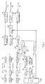
- FIG.2 shows part of an optical disk drive apparatus in accordance with the preferred embodiment of the present invention.
- An optical head 10 is composed of a coarse actuator 20 and a fine actuator 30.
- the coarse actuator 20 is supported by a rail 22 so that it can move freely in the radius direction of an optical disk 100 (in the direction of a seek operation), and is driven in the direction of the seek operation by a coarse actuator VCM (Voice Coil Motor) 24.
- VCM Vehicle Coil Motor
- the fine actuator 30 is supported by the coarse actuator 20 through a shaft 32 so that it can move in the focusing and tracking directions and is driven in the focusing direction and in the tracking direction by a focus VCM 34 and a tracking VCM 36 respectively.
- the fine actuator 30 has an objective lens 38 fixed from which a laser beam 40 is projected onto the optical disk 100.
- the coarse actuator 20 is provided with a relative position error (RPE) detecting sensor 25, a focus error signal (FES) detecting sensor 27, and a tracking error signal (TES) detecting sensor 29.
- the relative position error (RPE) detecting sensor 25, for example a split photo sensor with two sensitive parts detects the quantity of a relative deflection (rotational deflection from a neutral position) of the fine actuator 30 from the coarse actuator 20.
- the focus error signal (FES) detecting sensor 27, for example a split photo sensor with four sensitive parts detects a positional difference of a spot of the laser beam 40 from a focusing point on the optical disk 100.
- FIG.1 shows another part of the preferred embodiment.
- an output from the relative position error (RPE) detecting sensor 25 is input to a RPE calculator 52.
- the RPE calculator 52 if the RPE detecting sensor 25 is, for example, a split photo sensor with two sensitive parts, calculates a difference between detected signals from the two photo-sensitive parts and then outputs an unadjusted or raw RPE.
- An RPE adjuster 54 is used to adjust the gain or offset of unadjusted RPE and the resultant adjusted RPE is then provided to a coarse servo controller 56.
- the RPE after low-pass filtering and compensation for phase progress by the coarse servo controller 56, is provided to a coarse actuator VCM driver 58 from which driving current according to the amplitude and the sign of the RPE, that is, the quantity and the direction of the deflection of the fine actuator 30 to the coarse actuator 20 is provided to the coarse actuator VCM 24.
- An output from the FES detecting sensor 27 is input to a FES calculator 62.
- the FES calculator 62 calculates a difference between a sum of detected signals from a pair of two photo sensitive parts positioned diagonally to each other and a sum of detected signals from the remaining pair of two photo-sensitive parts also positioned diagonally to each other, and then outputs an unadjusted FES.
- the offset of the unadjusted FES is then adjusted by a FES adjuster 64, and the resultant adjusted FES is provided to a focus servo controller 66.
- the FES after low-pass filtering and compensation for phase progress by the focus servo controller 66, through a gain control means 300, is provided to a focus VCM driver 68 from which driving current according to the amplitude and sign of the FES, that is, a positional deviation amplitude and a deviation direction of a spot of the laser beam 40 from the focus point, is provided to the focus VCM 34.
- the focus error signal (FES) detecting sensor 27 the FES calculator, the FES adjuster, the focus servo controller 66, and the gain control means 300 compose the focusing means.
- An output from the TES detecting sensor 29 is input to a TES calculator 72.
- the TES calculator 72 for example, if the TES detecting sensor 29 is a split photo sensor with two sensitive parts, calculates a difference between detected signals from a pair of two photo sensitive parts to produce an unadjusted or raw TES.
- the gain and offset of the unadjusted TES are then adjusted by the TES adjuster 74 to form an adjusted TES and the TES thus obtained is provided to the fine servo controller 76, a fine actuator VCM driver 78 providing a driving signal which is provided to the tracking VCM 36.
- the adjusted TES is also input to a track crossing detector 82 in which the number of times when the optical head 10 (that is, a beam spot) crosses the tracks is detected based on a waveform of the TES; the result of such detection is provided to a track counter 84.
- a servo system controller CPU plus logic circuit
- a value contained in the track counter 84 is decreased by subtraction each time the optical head 10 crosses one track during the seek operation.
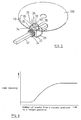
- the controller 200 is provided with a velocity profile ROM 86 in which information, for example, the relation between a track distance from a current position to the target position and a desired velocity, as in FIG.3, used for controlling the seek velocity is stored.
- the velocity profile ROM 86 outputs a desired velocity, represented as a digital value, at the current position to a velocity profile generator 88 in which the digital value is converted to an analog value which is output to a seek block 90.
- the seek block 90 compares the value obtained from the velocity profile generator 88 with the current velocity information conveyed by the TES to produce a positioning error signal (PES) which is an integrated value of the result of comparison.
- PES positioning error signal
- the PES is provided to a selector 92 to which the TES as well as the PES is provided.
- the selector 92 provides the PES to the fine servo controller 76, but in tracking operation mode, the selector 92 provides the TES to the fine servo controller 76.
- the selector 92 may provide PES to not only the fine servo controller 76 but the coarse servo controller 56.
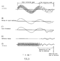
- the seek operation of the preferred embodiment will now be described with reference to FIG.4(A) to FIG.4(E).
- the number of tracks from a seek start position to a target position is stored in the track counter 84 and the stored value is decreased by subtraction each time the optical head crosses a track during the seek operation.
- a seek velocity is determined based on the value stored in the track counter 84 by reference to a velocity profile (FIG.3) in the velocity profile ROM 86.
- the seek operation is performed at a high velocity.
- the control gain of said focusing means is intended to remain the same as the value of a control gain during a period of a track following operation. If the controller 200 detects that the value contained in the track counter 84 has dropped to a predetermined value at a time when the seek operation is nearly completed, the controller 200 provides a control signal to the gain control means 300 to decrease the control gain of said focusing means to a predetermined value.
- the control gain of the focusing means causes the effect of scattering due to a groove in track crossing conveyed by the FES to be reduced, as shown in FIG.4(A).
- the movement of the lens (FIG.4(C)) following the swing of disk surface (FIG.4(B)) is improved during the low-velocity seek operation to decrease the quantity of defocus (FIG.4(D)).
- the amplitude of the TES is not decreased during the low-velocity seek operation and the proper TES required for controlling the seek operation can be obtained to perform the seek operation without disturbance, as shown in FIG.4(E).
- control gain of the focusing means in this embodiment is varied according to the value stored in the track counter 84, however it will be recognized that the control gain of the focusing means may be varied based on information relating to the seek velocity.
- control gain of the focusing means in this embodiment is varied either high or low, however it will be appreciated that the control gain of the focusing means may also be varied more than two stages or regardless of stages.
- the components of high frequency in the FES produced during the high-velocity seek operation are not specially removed in this embodiment, however it will be appreciated also that said components of high frequency may be removed by the low-pass filter.
- a proper TES can be obtained regardless of seek velocity to properly control a seek operation.
Landscapes
- Moving Of The Head For Recording And Reproducing By Optical Means (AREA)
- Optical Recording Or Reproduction (AREA)
Claims (4)
- Eine optische Platteneinheit mit einem Laser zum Abstrahlen eines Laserstrahls auf eine optische Platte (100), Spurverfolgungsmittel (29, 72 - 78) zum Steuern der Projektionsstellung des Laserstrahls zum Verfolgen der Spur bzw. der Spuren auf der optischen Platte, Fokussiermittel (27, 62 - 68), die auf Fehler in der Fokussierung des Laserstrahls auf die Spur ansprechen, um die Projektion des Laserstrahls zu steuern, so daß der Laserstrahl auf die Aufzeichnungsfläche der optischen Platte fokussiert wird, und Informationsabrufmittel zum Abrufen der aufgezeichneten Daten auf der Grundlage eines von der optischen Platte reflektierten Strahls oder eines durch die optische Platte übertragenen Strahls, wobei das Gerät gekennzeichnet ist durch
eine Verstärkungs-Steuerung (300) zum Einstellen der Empfindlichkeit des Fokussiermittels als Reaktion auf eine Suchgeschwindigkeit, mit der die Projektionsposition des Laserstrahls die Spuren der optischen Platte überstreicht, wobei die Verstärkung des Fokussiermittels während der Periode der langsamen Geschwindigkeit der Suchoperation reduziert wird. - Eine optische Platteneinheit gemäß Anspruch 1, bei der das Fokussiermittel einen Servoregelkreis aufweist und die Verstärkungssteuerung die Empfindlichkeit des Fokussiermittels einstellt durch Verringern der Verstärkung eines Fokus-Servoregelkreises kurz vor Abschluß einer Suchoperation eines optischen Kopfes, der den Laser enthält.
- Eine optische Platteneinheit gemäß Anspruch 1 oder 2, die ferner ein Geschwindigkeitsprofil aufweist, das ein Verhältnis zwischen einem Abstand von einer augenblicklichen Position zu einer Zielposition und der Suchgeschwindigkeit repräsentiert, wobei die Suchgeschwindigkeit durch den Abstand und das Geschwindigkeitsprofil bestimmt wird, und wobei die Verstärkungssteuerung die Empfindlichkeit des Fokussiermittels mindert, sobald der Abstand von der augenblicklichen Position zu einer Zielposition einen bestimmten vorgegebenen Wert erreicht.
- Eine optische Platteneinheit gemäß einem beliebigen der vorstehenden Ansprüche, die ferner einen Spurenzähler beinhaltet, der laufend die Anzahl der Spuren verzeichnet, die zwischen einer augenblicklichen Spur und einer Zielspur gekreuzt werden.
Applications Claiming Priority (2)
| Application Number | Priority Date | Filing Date | Title |
|---|---|---|---|
| JP2255467A JP2531847B2 (ja) | 1990-09-27 | 1990-09-27 | 光学ディスク駆動装置 |
| JP255467/90 | 1990-09-27 |
Publications (2)
| Publication Number | Publication Date |
|---|---|
| EP0478200A1 EP0478200A1 (de) | 1992-04-01 |
| EP0478200B1 true EP0478200B1 (de) | 1995-11-08 |
Family
ID=17279174
Family Applications (1)
| Application Number | Title | Priority Date | Filing Date |
|---|---|---|---|
| EP91308428A Expired - Lifetime EP0478200B1 (de) | 1990-09-27 | 1991-09-16 | Optische Platteneinheit |
Country Status (4)
| Country | Link |
|---|---|
| US (1) | US5384762A (de) |
| EP (1) | EP0478200B1 (de) |
| JP (1) | JP2531847B2 (de) |
| DE (1) | DE69114433T2 (de) |
Families Citing this family (8)
| Publication number | Priority date | Publication date | Assignee | Title |
|---|---|---|---|---|
| US5543697A (en) * | 1994-10-27 | 1996-08-06 | Sgs-Thomson Microelectronics, Inc. | Circuit and method for controlling the speed of a motor |
| US5982721A (en) * | 1996-03-29 | 1999-11-09 | Cirrus Logic, Inc. | Optical disc drive comprising switching gains for forcing phase states to follow a sliding line trajectory in a servo system |
| JP2001273647A (ja) * | 2000-03-29 | 2001-10-05 | Sanyo Electric Co Ltd | 光ディスク装置 |
| US7522480B2 (en) | 2001-01-25 | 2009-04-21 | Dphi Acquisitions, Inc. | Digital tracking servo system with multi-track seek with an acceleration clamp |
| US6898164B2 (en) * | 2001-01-25 | 2005-05-24 | Dphi Acquisitions, Inc. | Close tracking algorithm in a digital tracking servo system |
| TWI283403B (en) * | 2002-02-19 | 2007-07-01 | Via Tech Inc | Focus control method and device |
| GB0300173D0 (en) * | 2003-01-04 | 2003-02-05 | Infinite Data Storage Ltd | Improved optical storage device |
| JP4551883B2 (ja) * | 2005-04-28 | 2010-09-29 | パナソニック株式会社 | フォーカス制御調整方法および光ディスク装置 |
Family Cites Families (21)
| Publication number | Priority date | Publication date | Assignee | Title |
|---|---|---|---|---|
| JPS5641533A (en) * | 1979-09-06 | 1981-04-18 | Matsushita Electric Ind Co Ltd | Regenerative device |
| JPS57186239A (en) * | 1981-05-11 | 1982-11-16 | Sony Corp | Disc reproducing device |
| JPS58128031A (ja) * | 1982-01-24 | 1983-07-30 | Sony Corp | デイスク再生装置 |
| JPS60261035A (ja) * | 1984-06-06 | 1985-12-24 | Matsushita Electric Ind Co Ltd | 光学式情報記録再生装置 |
| JPS6129424A (ja) * | 1984-06-15 | 1986-02-10 | Olympus Optical Co Ltd | 光情報記録再生装置 |
| JPS61177642A (ja) * | 1985-01-31 | 1986-08-09 | Olympus Optical Co Ltd | 光学的情報記録再生装置 |
| JPH0736233B2 (ja) * | 1985-04-16 | 1995-04-19 | オリンパス光学工業株式会社 | 光学的情報記録再生装置 |
| JPS61260429A (ja) * | 1985-05-14 | 1986-11-18 | Olympus Optical Co Ltd | 光学的情報記録再生装置 |
| US4701603A (en) * | 1985-10-17 | 1987-10-20 | Optical Disc Corporation | Focus control system for optical information recorder or player |
| EP0232134B1 (de) * | 1986-02-07 | 1994-08-24 | Matsushita Electric Industrial Co., Ltd. | Optische Platte und Plattengerät zum Aufzeichnen oder Wiedergeben von Daten in oder von der Platte |
| DE3780866T2 (de) * | 1986-05-20 | 1993-03-18 | Canon Kk | Optisches informations-aufzeichnungs- und wiedergabegeraet. |
| JPS63119578A (ja) * | 1986-11-07 | 1988-05-24 | Seiko Epson Corp | 半導体装置 |
| JPS63241732A (ja) * | 1987-03-27 | 1988-10-07 | Matsushita Graphic Commun Syst Inc | 光デイスク装置のフオ−カスサ−ボ装置 |
| JPS63298822A (ja) * | 1987-05-29 | 1988-12-06 | Ricoh Co Ltd | 光ピックアップの制御方式 |
| US4982392A (en) * | 1987-07-10 | 1991-01-01 | Ricoh Company, Ltd. | Stabilized optical pick-up device inhibiting the effect of the focus error signal at the start and end of a data region |
| DE3887126T2 (de) * | 1987-08-29 | 1994-04-28 | Fujitsu Ltd | Methoden zum zugang einer optischen aufzeichnungsspur. |
| JPH01290130A (ja) * | 1988-05-17 | 1989-11-22 | Fujitsu Ltd | 光ディスク装置のフォーカスサーボ制御方法 |
| US5020045A (en) * | 1988-12-19 | 1991-05-28 | Eastman Kodak Company | Focus acquisition servo system and associated method |
| US5038333A (en) * | 1989-05-05 | 1991-08-06 | International Business Machines Corporation | Positioning systems including reliable track crossing detection for high speed relative motions |
| JP3139752B2 (ja) * | 1989-09-30 | 2001-03-05 | 株式会社 東芝 | ディスク再生装置 |
| US5140576A (en) * | 1989-11-10 | 1992-08-18 | Matsushita Electric Industrial Co., Ltd. | Method of and apparatus for setting focusing control into operation |
-
1990
- 1990-09-27 JP JP2255467A patent/JP2531847B2/ja not_active Expired - Lifetime
-
1991
- 1991-09-16 DE DE69114433T patent/DE69114433T2/de not_active Expired - Fee Related
- 1991-09-16 EP EP91308428A patent/EP0478200B1/de not_active Expired - Lifetime
-
1994
- 1994-02-04 US US08/191,738 patent/US5384762A/en not_active Expired - Fee Related
Also Published As
| Publication number | Publication date |
|---|---|
| DE69114433D1 (de) | 1995-12-14 |
| EP0478200A1 (de) | 1992-04-01 |
| JP2531847B2 (ja) | 1996-09-04 |
| US5384762A (en) | 1995-01-24 |
| DE69114433T2 (de) | 1996-06-20 |
| JPH04134729A (ja) | 1992-05-08 |
Similar Documents
| Publication | Publication Date | Title |
|---|---|---|
| US5199017A (en) | Optical disk drive and method for counting the number of tracks on an optical disk | |
| US5177718A (en) | Optical disk apparatus | |
| EP0478200B1 (de) | Optische Platteneinheit | |
| US5402402A (en) | Apparatus for controlling a optical disk drive | |
| EP0375266B1 (de) | Optisches Plattenaufzeichnungs- und/oder -wiedergabegerät | |
| JPH0460974A (ja) | トラッキングサーボ装置 | |
| US5255253A (en) | Apparatus and method for controlling the velocity of a disk storage head | |
| EP0558293B1 (de) | Optisches Aufzeichnungs-/Wiedergabeverfahren und Gerät dazu | |
| USRE36864E (en) | Optical disk drive and methods for counting the number of tracks on an optical disk | |
| EP0479473B1 (de) | Gerät und Verfahren zum Zählen der Anzahl von Spuren auf einer optischen Scheibe | |
| KR100211841B1 (ko) | 디지털 비디오 디스크 플레이어에서 슬레드 이득 자동조정장치 및 방법 | |
| JPH0612573B2 (ja) | 情報読取装置における記録トラックとピックアップとのトラック直交方向相対位置制御装置 | |
| US20070121439A1 (en) | Optical disc drive and method for controlling the position of a lens | |
| JP2774295B2 (ja) | 光学的情報記録再生装置 | |
| JP2576217B2 (ja) | 光ディスク装置のトラッキング制御装置 | |
| JPS63152030A (ja) | 光デイスクのトラツキング制御方法 | |
| KR100211211B1 (ko) | 디지털 비디오 디스크 플레이어에서 슬레드 이득 자동조정장치 및 방법 | |
| JP2718053B2 (ja) | フォーカスサーボのゲイン調整装置 | |
| JP2001084599A (ja) | 光ディスク装置 | |
| JP2734884B2 (ja) | アクセス制御装置 | |
| JPH06187645A (ja) | 光ディスクのトラッキング制御装置 | |
| JPH0450657B2 (de) | ||
| JPH0594679A (ja) | トラツクアクセス装置 | |
| KR19980086261A (ko) | 디지털 비디오 디스크 플레이어에서 슬레드 이득 자동 조정장치 및 방법 | |
| JPS63281230A (ja) | 光ピックアップのフォ−カスサ−ボ装置 |
Legal Events
| Date | Code | Title | Description |
|---|---|---|---|
| PUAI | Public reference made under article 153(3) epc to a published international application that has entered the european phase |
Free format text: ORIGINAL CODE: 0009012 |
|
| AK | Designated contracting states |
Kind code of ref document: A1 Designated state(s): DE FR GB |
|
| 17P | Request for examination filed |
Effective date: 19920817 |
|
| 17Q | First examination report despatched |
Effective date: 19950103 |
|
| GRAA | (expected) grant |
Free format text: ORIGINAL CODE: 0009210 |
|
| AK | Designated contracting states |
Kind code of ref document: B1 Designated state(s): DE FR GB |
|
| REF | Corresponds to: |
Ref document number: 69114433 Country of ref document: DE Date of ref document: 19951214 |
|
| ET | Fr: translation filed | ||
| PLBE | No opposition filed within time limit |
Free format text: ORIGINAL CODE: 0009261 |
|
| STAA | Information on the status of an ep patent application or granted ep patent |
Free format text: STATUS: NO OPPOSITION FILED WITHIN TIME LIMIT |
|
| PG25 | Lapsed in a contracting state [announced via postgrant information from national office to epo] |
Ref country code: GB Effective date: 19960916 |
|
| 26N | No opposition filed | ||
| GBPC | Gb: european patent ceased through non-payment of renewal fee |
Effective date: 19960916 |
|
| PG25 | Lapsed in a contracting state [announced via postgrant information from national office to epo] |
Ref country code: DE Effective date: 19970603 |
|
| PG25 | Lapsed in a contracting state [announced via postgrant information from national office to epo] |
Ref country code: FR Effective date: 19970630 |
|
| REG | Reference to a national code |
Ref country code: FR Ref legal event code: ST |
|
| REG | Reference to a national code |
Ref country code: FR Ref legal event code: ST |