EP0480080A1 - Beschichtungsvorrichtung - Google Patents
Beschichtungsvorrichtung Download PDFInfo
- Publication number
- EP0480080A1 EP0480080A1 EP90119288A EP90119288A EP0480080A1 EP 0480080 A1 EP0480080 A1 EP 0480080A1 EP 90119288 A EP90119288 A EP 90119288A EP 90119288 A EP90119288 A EP 90119288A EP 0480080 A1 EP0480080 A1 EP 0480080A1
- Authority
- EP
- European Patent Office
- Prior art keywords
- paint
- flow rate
- valve
- coating machine
- color change
- Prior art date
- Legal status (The legal status is an assumption and is not a legal conclusion. Google has not performed a legal analysis and makes no representation as to the accuracy of the status listed.)
- Withdrawn
Links
- 239000011248 coating agent Substances 0.000 title claims abstract description 65
- 238000000576 coating method Methods 0.000 title claims abstract description 65
- 239000003973 paint Substances 0.000 claims abstract description 146
- 239000003086 colorant Substances 0.000 claims description 10
- 238000004140 cleaning Methods 0.000 description 10
- 238000009500 colour coating Methods 0.000 description 4
- 238000009434 installation Methods 0.000 description 3
- MJFJKKXQDNNUJF-UHFFFAOYSA-N metixene Chemical compound C1N(C)CCCC1CC1C2=CC=CC=C2SC2=CC=CC=C21 MJFJKKXQDNNUJF-UHFFFAOYSA-N 0.000 description 3
- 230000000694 effects Effects 0.000 description 2
- 229910000831 Steel Inorganic materials 0.000 description 1
- 239000012777 electrically insulating material Substances 0.000 description 1
- 239000012530 fluid Substances 0.000 description 1
- 238000000034 method Methods 0.000 description 1
- 239000010959 steel Substances 0.000 description 1
- 238000011144 upstream manufacturing Methods 0.000 description 1
Images

Classifications
-
- B—PERFORMING OPERATIONS; TRANSPORTING
- B05—SPRAYING OR ATOMISING IN GENERAL; APPLYING FLUENT MATERIALS TO SURFACES, IN GENERAL
- B05B—SPRAYING APPARATUS; ATOMISING APPARATUS; NOZZLES
- B05B12/00—Arrangements for controlling delivery; Arrangements for controlling the spray area
- B05B12/14—Arrangements for controlling delivery; Arrangements for controlling the spray area for supplying a selected one of a plurality of liquids or other fluent materials or several in selected proportions to a spray apparatus, e.g. to a single spray outlet
- B05B12/149—Arrangements for controlling delivery; Arrangements for controlling the spray area for supplying a selected one of a plurality of liquids or other fluent materials or several in selected proportions to a spray apparatus, e.g. to a single spray outlet characterised by colour change manifolds or valves therefor
-
- B—PERFORMING OPERATIONS; TRANSPORTING
- B05—SPRAYING OR ATOMISING IN GENERAL; APPLYING FLUENT MATERIALS TO SURFACES, IN GENERAL
- B05B—SPRAYING APPARATUS; ATOMISING APPARATUS; NOZZLES
- B05B12/00—Arrangements for controlling delivery; Arrangements for controlling the spray area
- B05B12/08—Arrangements for controlling delivery; Arrangements for controlling the spray area responsive to condition of liquid or other fluent material to be discharged, of ambient medium or of target ; responsive to condition of spray devices or of supply means, e.g. pipes, pumps or their drive means
- B05B12/085—Arrangements for controlling delivery; Arrangements for controlling the spray area responsive to condition of liquid or other fluent material to be discharged, of ambient medium or of target ; responsive to condition of spray devices or of supply means, e.g. pipes, pumps or their drive means responsive to flow or pressure of liquid or other fluent material to be discharged
-
- B—PERFORMING OPERATIONS; TRANSPORTING
- B05—SPRAYING OR ATOMISING IN GENERAL; APPLYING FLUENT MATERIALS TO SURFACES, IN GENERAL
- B05B—SPRAYING APPARATUS; ATOMISING APPARATUS; NOZZLES
- B05B12/00—Arrangements for controlling delivery; Arrangements for controlling the spray area
- B05B12/14—Arrangements for controlling delivery; Arrangements for controlling the spray area for supplying a selected one of a plurality of liquids or other fluent materials or several in selected proportions to a spray apparatus, e.g. to a single spray outlet
-
- G—PHYSICS
- G05—CONTROLLING; REGULATING
- G05D—SYSTEMS FOR CONTROLLING OR REGULATING NON-ELECTRIC VARIABLES
- G05D7/00—Control of flow
- G05D7/06—Control of flow characterised by the use of electric means
- G05D7/0617—Control of flow characterised by the use of electric means specially adapted for fluid materials
- G05D7/0623—Control of flow characterised by the use of electric means specially adapted for fluid materials characterised by the set value given to the control element
Definitions
- the present invention concerns a coating apparatus having a valve disposed in a paint supply path extended from a coating supply source to a coating machine for controlling the flow rate of a paint in accordance with the amount of a paint discharged from the coating machine.
- a pressure control valve air-operated paint regulator
- a pressure control valve has been disposed on each of paint supply pipelines for supplying the paint of each color under pressure from each of paint supply sources to the color change valve device, or a pressure control valve has been disposed to a paint pipeline such as a paint hose that connects the coating machine with the color change valve device, and the flow rate of the paint supplied to the coating machine has been controlled by adjusting the opening degree of the pressure control valve (refer, for example, to Japanese Patent Publication Sho 59-1106 and Japanese Patent Laid Open Sho 60-61077).
- a pressure control valve can not precisely control the paint flow rate, it involves a drawback that high quality coating under accurate control for the flow rate of the paint discharged from the coating machine is impossible.
- the gear pump has an excellent performance of supplying fluid at a constant flow rate and, accordingly, the flow rate of the paint can be controlled precisely by controlling the number of rotation of the gear pump.
- the gear pump when the gear pump is disposed to the paint pipeline that connects the coating machine with the color change valve device, it requires troublesome cleaning for residual paint deposited to gears, etc. of the gear pump, resulting in a difficulty for rapid color change and, thus, reducing the coating productivity.
- gear pump is disposed to each of the paint supply pipelines connected between the paint supply sources for the paints of respective colors and the color change valve device, and the flow rate of the paint is controlled by the gear pump disposed exclusively for the paint of each of the colors, cleaning operation for the inside of the gear pump can be saved upon color change.
- this requires expensive gear pumps by the number corresponding to that of colors of the paints and, it results in a drawback of remarkably increasing the installation cost.
- a technical object of the present invention to provide a coating apparatus capable of precisely coating the flow rate of a paint supplied to a coating machine in accordance with the flow rate of a paint discharged from the coating machine, as well as capable of rapidly changing the paint color, in particular, in a multi-color coating apparatus with no increase of installation cost.
- a coating apparatus having a valve means disposed to a paint supply means extended from a paint supply source to a coating machine for controlling the flow rate of a paint in accordance with the flow rate of a paint discharged from the coating machine, wherein the valve means comprises:
- the movable core energized by the solenoid coils is attracted against the resiliency of the spring and, consequently, the needle valve resiliently urged so far by the spring in the direction of closing the flow channel of the paint is moved in the direction opposite to the urging direction, to open the flow channel of the paint.
- the needle valve When the electric pulse from the electric pulse generation means is interrupted, the needle valve is urged by the resiliency of the spring in the direction of closing the flow channel of the paint again.
- the needle valve is vibrated at a vibration cycle in accordance with the pulse rate, repeats rapid opening/losing operation and delivers the paint at a flow rate determined in accordance with the velocity of the opening/closing operation and the duration time of the electric pulses supplied to the solenoid coils.
- the flow rate of the paint supplied to the coating machine can be controlled precisely in accordance with the flow rate of the paint discharged from the coating machine.
- valve means for controlling the flow rate of the paint by the opening/closing operation of the needle valve has no such complicate inner shape and structure as in the gear pump, when the apparatus is applied to the multi-color coating apparatus, rapid color change is possible with no troublesome cleaning.
- valve means is disposed to each of paint supply pipelines that connects the paint supply source for the paint of each color and the color change valve device, or in another preferred embodiment in which it is used also as a color change valve disposed along the manifold of the color change valve device, cleaning for the inside of the valve upon color change is no more necessary and color can be changed more rapidly.
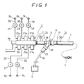
- a flow rate control valve means 4 is disposed in the midway of a paint pipeline 3, which is connected between a coating machine 1 and a color change valve device 2, for controlling the flow rate of a paint supplied to the coating machine 1 in accordance with the flow rate of a paint discharged from the coating machine 1.
- the flow rate control valve means 4 has a needle valve 6 disposed in a valve body 5.
- a valve head 9 is secured to one end of the needle vale 6 for opening and closing a paint exit 8 that discharges a paint of each color selectively supplied from each of color change valves CV, - CV 5 arranged along a manifold 7 of the color change valve device 2.
- a movable core 12 is secured to other end of the needle valve 6 for abutting the valve head 9 against a valve seat 11 by the resiliency of a spring 10.
- solenoid coils 14 for lifting (leftward in the drawing) the movable core 12 against the resiliency of the spring 10 when electric pulses generated from an electric pulse generator 13 at a predetermined pulse period is inputted and a stopper 16 against which a flange 15 of the needle valve 6 is abutted when the latter is fully opened by the attraction of the movable core 12, so that the needle valve 6 moves by a stroke corresponding to a gap formed between the flange 15 and the stopper 16 to open and close the paint exit 8.
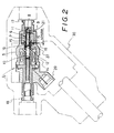
- valve body 5 of the flow rate control valve means 4 shown in Fig. 2 has connectors 17 and 18 formed on both right and left ends each for connection with the paint pipeline 3, and an electric connector 20 disposed for connection with lead wires 19 that input the electric pulses generated from the electric pulse generator 13 to the solenoid coils 14. Further, an explosion-proof casing 30 is disposed to the outer side of the valve body 5 for covering the latter entirely.
- the needle valve 6 comprises a tubular pipe P defining a paint channel therein, and the tubular pipe P has a paint discharge port, 21 formed at one end upstream to the valve body 9 made of steel ball and a paint inlet port 22 that formed at the other end toward the connector portion 18.
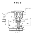
- a paint inlet port 22 is apertured through the circumferential wall of the valve body 5 near the valve head 9 of the needle valve 6, and a connector 18 is disposed to the paint inlet port 22 being protruded in the direction perpendicular to the connector 17 on the side of the paint exit 8, instead of forming the needle valve 6 with the tubular pipe P as in the previous embodiment.
- the paint pipeline 3 or the pipeline 23 for lead wires 19 are made of electrically insulating material.
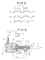
- the electric pulse generator 13 is adapted to generate a train of electric pulses each comprising a unitary pulse period T z composed of a pulse duration rimw T i -(ON time) and a pulse rest time T rest (OFF time).
- the paint is discharged from the paint exit 8 to the coating machine 1.
- the flow rate of the paint discharged from the exit 8 depends on the stroke of the needle valve 6, the opening area of the paint exit 8, the pressure between the inside and the outside of the opening, etc. If such factors are predetermined, the discharge flow rate is determined by the valve opening period of the needle valve 6, that is, the duration time T ; of the electric pulse.
- the flow rate of the paint discharged per unit time by the opening/closing operation of the needle valve 6 is determined by the pulse duration time T i or the pulse period T z .
- the flow rate of the paint supplied to the coating machine 1 can optionally be controlled either by changing the pulse duration time T i while fixing the pulse period T z constant, for example, to 10 ms ((a) and (b)), or by changing the pulse period T z while fixing the pulse duration time T i constant (c), in other words, by varying the pulse duty ratio.
- the flow rate control valve means 4 is opened and closed at a predetermined opening/closing rate corresponding to the pulse period T z (or pulse rate) of the electric pulses inputted to the solenoid coils 14 and supplies the paint to the coating machine 1 at a predetermined flow rate which is determined in accordance with the opening/closing rate and the pulse duration T ; .
- the flow rate of the paint supplied to the coating machine 1 can be controlled precisely and accurately by changing the pulse period T z or the pulse duration T i of the electric pulses generated from the electric pulse generator 13.
- the stroke of the needle valve 6 for opening and closing the flow rate control valve 4 and the opening area of the paint exit 8 are always constant, but the pressure of the paint may sometimes fluctuate depending on the change of the viscosity, etc. Also in this case, accurate flow rate control can be attained by continuously detecting the change of the pressure by pressure sensors 24 and 25 disposed on both sides of the flow rate control valve means 4 and variably controlling the pulse period T z andthe pulse duration T i of the electric pulses generated from the electric pulse generator 13 in accordance with the change of the detected pressure.
- the flow rate control valve mean 4 is disposed to the paint pipeline 3 that connects the coating machine 1 and the color change valve device 2.
- the flow rate control valve 4 may be disposed to each of the paint supply pipelines 26, 26, --- connected between each of the paint supply sources B 1 , B 5 for the paint of each of colors and each of the color change valves CV 1 - CV 5 of the color change valve device 2 respectively, so that the flow rate of the paint supplied under pressure from each of the paint supply pipelines 26 to each of the color change valves CV 1 - CV 5 by means of a pump 27 may be controlled respectively.
- the color control valve means 4 is necessary by the number of paints of respective colors, but the installation cost is greatly reduced as compared with the case of using expensive gear pumps to the pumps 27, 27 --- for supplying the paints of respective colors by way of the color change valves CV 1 - CV 5 to the coating machine 1 respectively.
- the flow rate control valve means 4 shown in Figs 2 and 4 can be served also as each of the color change valves CV 1 - CV 5 by connecting a paint supply pipeline 26 to the paint inlet port 22, while connecting the paint exit 8 thereof to the inside of the manifold 7 of the color change valve device 2.
- Fig. 5 is a schematic view illustrating a concrete embodiment of the entire apparatus and Fig. 6 is a cross sectional view illustrating one embodiment of the flow rate control valve means 4 used also as a color change valve.
- Each of the flow rate control valve means 4 constitutes each of the color change valves CV 1 - CV 7 disposed along the manifold 7 of the color change valve device 2 as shown in Fig. 5.
- each of the flow rate control valve means 4 constituting each of the color change valves CV 1 - CV 7 respectively is connected at the paint inlet 22 thereof by way of a paint supply pipeline 26 with each of the paint flow supply sources B i - B 7 for each of the paints of different colors and connected at the paint exit 8 thereof by way of a paint pipeline 3 to the inside of the manifold 7 connected to the coating machine 1.
- valve CV 1 is opened to selectively send the paint which is supplied under pressure by the pump 27 from the paint supply source B 1 to the coating machine 1, electric pulses are inputted each at a pulse duration T i and a predetermined pulse period T z in accordance with the flow rate of a paint discharged from the coating machine 1 to the solenoid coils 14 of the color change valve CV 1 , and the paint is continuously delivered at a predetermined flow rate from the paint exit 8, which is rapidly opened and closed by the vibrations of the needle valve 6, to the inside of the manifold 7.
- the pressure of the paint supplied under pressure by the pump 27 may sometimes fluctuate depending on the change of the viscosity, etc.
- the pressure of the paint supplied under pressure to the color change valve for example, valve CV 1 and the pressure at the inside of the manifold 7 are detected by pressure sensors 28, 29, and the pulse duration T i and the pulse period T z of the electric pulses generated from the electric pulse generator 13 are variously controlled appropriately in accordance with the change of the pressure detected.
- the color change valves CV 1 - CV 7 can change the color of the paint supplied to the coating machine 1, as well as can control the flow rate of the paint.
- the flow rate is controlled not by the change of the valve opening degree as in the case of using the pressure control valve in the prior art but by changing the opening/closing rate of the valve, the flow rate of the paint supplied to the coating machine 1 can be controlled precisely and accurately.
- each of the color change valves CV 1 - CV 7 is automatically closed by the abutment of the valve head 9 of the needle valve 6 against the valve seat 8 by the resiliency of the spring 10.
- excess cleaning time is no more required.
- the paint can be circulated by disposing a paint circulation port 31 to the valve body 5 for each of the color change valves CV 1 - CV 7 , and connecting a paint circulation pipeline 33 by means of an ON-OFF valve 32 between the paint circulation port 31 and each of the paint supply sources B i - B 7 .
- the coating apparatus according to the present invention can provide excellent effects capable of precisely and accurately controlling the flow rate of a paint supplied to the coating machine and providing high quality coating without using an expensive gear pump, etc.
- the present invention can also provide excellent effect capable of precisely controlling the flow rate of the paint of each color, as well as rapidly changing the color of the paint.
Landscapes
- Physics & Mathematics (AREA)
- General Physics & Mathematics (AREA)
- Engineering & Computer Science (AREA)
- Automation & Control Theory (AREA)
- Spray Control Apparatus (AREA)
Priority Applications (1)
| Application Number | Priority Date | Filing Date | Title |
|---|---|---|---|
| EP90119288A EP0480080A1 (de) | 1990-10-08 | 1990-10-08 | Beschichtungsvorrichtung |
Applications Claiming Priority (1)
| Application Number | Priority Date | Filing Date | Title |
|---|---|---|---|
| EP90119288A EP0480080A1 (de) | 1990-10-08 | 1990-10-08 | Beschichtungsvorrichtung |
Publications (1)
| Publication Number | Publication Date |
|---|---|
| EP0480080A1 true EP0480080A1 (de) | 1992-04-15 |
Family
ID=8204592
Family Applications (1)
| Application Number | Title | Priority Date | Filing Date |
|---|---|---|---|
| EP90119288A Withdrawn EP0480080A1 (de) | 1990-10-08 | 1990-10-08 | Beschichtungsvorrichtung |
Country Status (1)
| Country | Link |
|---|---|
| EP (1) | EP0480080A1 (de) |
Cited By (4)
| Publication number | Priority date | Publication date | Assignee | Title |
|---|---|---|---|---|
| EP1205256A3 (de) * | 2000-11-14 | 2004-12-08 | Dürr Systems GmbH | Farbwechselventilanordnung und Verfahren zu ihrer Steuerung |
| EP1287900A3 (de) * | 2001-08-30 | 2005-12-07 | Dürr Systems GmbH | Beschichtungsanlage mit einem Regelkreis |
| CN101161357B (zh) * | 2006-10-11 | 2013-06-12 | 诺信公司 | 细线保形涂敷设备和方法 |
| EP4245422A1 (de) * | 2022-03-14 | 2023-09-20 | Ricoh Company, Ltd. | Flüssigkeitsabgabevorrichtung, flüssigkeitsabgabeverfahren und trägermedium |
Citations (4)
| Publication number | Priority date | Publication date | Assignee | Title |
|---|---|---|---|---|
| US4163523A (en) * | 1976-12-15 | 1979-08-07 | Vincent Raymond A | Multicolor paint dispensing system having a pressure responsive color change valve |
| FR2528726A1 (fr) * | 1982-06-22 | 1983-12-23 | Sames Sa | Dispositif mobile de projection de peinture par pulverisation |
| EP0229632A2 (de) * | 1986-01-10 | 1987-07-22 | Mks Instruments, Inc. | Durch einen Durchflussmesser gesteuertes Ventil |
| EP0292354A1 (de) * | 1987-05-19 | 1988-11-23 | Sames S.A. | Anlage mit einer Pumpe zum Spritzen eines Beschichtungsstoffes |
-
1990
- 1990-10-08 EP EP90119288A patent/EP0480080A1/de not_active Withdrawn
Patent Citations (4)
| Publication number | Priority date | Publication date | Assignee | Title |
|---|---|---|---|---|
| US4163523A (en) * | 1976-12-15 | 1979-08-07 | Vincent Raymond A | Multicolor paint dispensing system having a pressure responsive color change valve |
| FR2528726A1 (fr) * | 1982-06-22 | 1983-12-23 | Sames Sa | Dispositif mobile de projection de peinture par pulverisation |
| EP0229632A2 (de) * | 1986-01-10 | 1987-07-22 | Mks Instruments, Inc. | Durch einen Durchflussmesser gesteuertes Ventil |
| EP0292354A1 (de) * | 1987-05-19 | 1988-11-23 | Sames S.A. | Anlage mit einer Pumpe zum Spritzen eines Beschichtungsstoffes |
Non-Patent Citations (1)
| Title |
|---|
| ELECTRONICS & WIRELESS WORLD, no. 1614, April 1987, pages 415-420, Sutton, Surrey, GB; B. FRIEDMAN: "Modulated-pulse amplifiers revived" * |
Cited By (5)
| Publication number | Priority date | Publication date | Assignee | Title |
|---|---|---|---|---|
| EP1205256A3 (de) * | 2000-11-14 | 2004-12-08 | Dürr Systems GmbH | Farbwechselventilanordnung und Verfahren zu ihrer Steuerung |
| EP1287900A3 (de) * | 2001-08-30 | 2005-12-07 | Dürr Systems GmbH | Beschichtungsanlage mit einem Regelkreis |
| CN101161357B (zh) * | 2006-10-11 | 2013-06-12 | 诺信公司 | 细线保形涂敷设备和方法 |
| EP4245422A1 (de) * | 2022-03-14 | 2023-09-20 | Ricoh Company, Ltd. | Flüssigkeitsabgabevorrichtung, flüssigkeitsabgabeverfahren und trägermedium |
| US12350942B2 (en) | 2022-03-14 | 2025-07-08 | Ricoh Company, Ltd. | Liquid discharge apparatus, liquid discharge method, and storage medium |
Similar Documents
| Publication | Publication Date | Title |
|---|---|---|
| US4979542A (en) | Pulse modulated hydraulic valve | |
| KR100499738B1 (ko) | 접착제도포장치 | |
| US4962871A (en) | Applicator utilizing high speed non-contact extrusion valve | |
| EP0756293A2 (de) | Verfahren zur Steuerung der Magnetspaltlänge und der anfänglichen Hublänge einer Kraftstoffdruckpumpe | |
| US5630552A (en) | Paint dosage device for program controlled spray painting system | |
| EP0132958A2 (de) | Dreiwegekegelventil | |
| JPH02159401A (ja) | アクチュエータ | |
| CA2238994A1 (en) | Ultrasonic liquid flow control apparatus and method | |
| US7086613B2 (en) | Lightweight solenoid-operated spray gun | |
| US7093778B1 (en) | Device for delivering and/or spraying flowable media, especially fluids | |
| US5441232A (en) | Solenoid valve | |
| EP0480080A1 (de) | Beschichtungsvorrichtung | |
| JPH0466148A (ja) | 塗装方法 | |
| JPH0262752B2 (de) | ||
| CA2028939A1 (en) | Coating apparatus | |
| US5878960A (en) | Pulse-wave-modulated spray valve | |
| EP0473451A1 (de) | Verfahren und Vorrichtung zur Regelung des Gasdurchflusses in einem Spektrometer | |
| KR950013983B1 (ko) | 도장장치 | |
| JP2506194B2 (ja) | 多色塗装装置 | |
| JP3325966B2 (ja) | 塗装用弁装置 | |
| JPH0330857A (ja) | 塗料色替装置 | |
| EP0795355A2 (de) | Nebenleitung einer Umlaufanlage | |
| JPH05329407A (ja) | 静電塗装方法および装置 | |
| JPS5834065A (ja) | 塗料の吐出量制御方法 | |
| KR0167059B1 (ko) | 자동차 차체 도장도료 변경장치의 도장도료 절감장치 |
Legal Events
| Date | Code | Title | Description |
|---|---|---|---|
| PUAI | Public reference made under article 153(3) epc to a published international application that has entered the european phase |
Free format text: ORIGINAL CODE: 0009012 |
|
| AK | Designated contracting states |
Kind code of ref document: A1 Designated state(s): DE FR GB |
|
| STAA | Information on the status of an ep patent application or granted ep patent |
Free format text: STATUS: THE APPLICATION IS DEEMED TO BE WITHDRAWN |
|
| 18D | Application deemed to be withdrawn |
Effective date: 19921016 |