EP0480585A2 - Dispositif de transport de plaquettes à circuits imprimés - Google Patents
Dispositif de transport de plaquettes à circuits imprimés Download PDFInfo
- Publication number
- EP0480585A2 EP0480585A2 EP91308346A EP91308346A EP0480585A2 EP 0480585 A2 EP0480585 A2 EP 0480585A2 EP 91308346 A EP91308346 A EP 91308346A EP 91308346 A EP91308346 A EP 91308346A EP 0480585 A2 EP0480585 A2 EP 0480585A2
- Authority
- EP
- European Patent Office
- Prior art keywords
- clamp plate
- printed circuit
- members
- engaging
- circuit board
- Prior art date
- Legal status (The legal status is an assumption and is not a legal conclusion. Google has not performed a legal analysis and makes no representation as to the accuracy of the status listed.)
- Granted
Links
- 238000005476 soldering Methods 0.000 description 4
- 238000004140 cleaning Methods 0.000 description 3
- 239000000969 carrier Substances 0.000 description 1
- 238000010276 construction Methods 0.000 description 1
- 239000007788 liquid Substances 0.000 description 1
- 238000005096 rolling process Methods 0.000 description 1
- 238000011144 upstream manufacturing Methods 0.000 description 1
Images



Classifications
-
- H—ELECTRICITY
- H05—ELECTRIC TECHNIQUES NOT OTHERWISE PROVIDED FOR
- H05K—PRINTED CIRCUITS; CASINGS OR CONSTRUCTIONAL DETAILS OF ELECTRIC APPARATUS; MANUFACTURE OF ASSEMBLAGES OF ELECTRICAL COMPONENTS
- H05K13/00—Apparatus or processes specially adapted for manufacturing or adjusting assemblages of electric components
- H05K13/0061—Tools for holding the circuit boards during processing; handling transport of printed circuit boards
-
- B—PERFORMING OPERATIONS; TRANSPORTING
- B65—CONVEYING; PACKING; STORING; HANDLING THIN OR FILAMENTARY MATERIAL
- B65G—TRANSPORT OR STORAGE DEVICES, e.g. CONVEYORS FOR LOADING OR TIPPING, SHOP CONVEYOR SYSTEMS OR PNEUMATIC TUBE CONVEYORS
- B65G17/00—Conveyors having an endless traction element, e.g. a chain, transmitting movement to a continuous or substantially-continuous load-carrying surface or to a series of individual load-carriers; Endless-chain conveyors in which the chains form the load-carrying surface
- B65G17/26—Conveyors having an endless traction element, e.g. a chain, transmitting movement to a continuous or substantially-continuous load-carrying surface or to a series of individual load-carriers; Endless-chain conveyors in which the chains form the load-carrying surface comprising a series of co-operating units, e.g. interconnected by pivots
-
- B—PERFORMING OPERATIONS; TRANSPORTING
- B65—CONVEYING; PACKING; STORING; HANDLING THIN OR FILAMENTARY MATERIAL
- B65G—TRANSPORT OR STORAGE DEVICES, e.g. CONVEYORS FOR LOADING OR TIPPING, SHOP CONVEYOR SYSTEMS OR PNEUMATIC TUBE CONVEYORS
- B65G2201/00—Indexing codes relating to handling devices, e.g. conveyors, characterised by the type of product or load being conveyed or handled
- B65G2201/02—Articles
-
- B—PERFORMING OPERATIONS; TRANSPORTING
- B65—CONVEYING; PACKING; STORING; HANDLING THIN OR FILAMENTARY MATERIAL
- B65G—TRANSPORT OR STORAGE DEVICES, e.g. CONVEYORS FOR LOADING OR TIPPING, SHOP CONVEYOR SYSTEMS OR PNEUMATIC TUBE CONVEYORS
- B65G2207/00—Indexing codes relating to constructional details, configuration and additional features of a handling device, e.g. Conveyors
- B65G2207/14—Combination of conveyors
Definitions
- This invention relates generally to a device for conveying printed circuit boards and, more specifically, to a device having a pair of endless conveyor chains adapted to support printed circuit boards directly thereon without employing carriers and to transfer same through a predetermined path of travel for effecting soldering.
- U. S. patent No. 4,874,081 discloses a printed circuit board conveying device for such a "carrierless" soldering apparatus as shown in Figs. 9-11 of the accompanying drawings.
- the device includes a pair of endless roller chains 2 each guided by a guide rail 3 to define a printed circuit board transferring path 4 therebetween.
- a plurality of support members 5 are fixed to the chains 2 for movement therewith and are each adapted to support printed circuit boards 1 thereon.
- a clamp plate member 6 is provided on each of the support members 5 and is moveable between close and open positions.
- Each of the support members 5 is provided with a spring member 7 to normally urge the clamp plate member 6 in the open position as shown by the solid line in Fig. 9.
- engaging plates 8 engageable with upper surfaces of the clamp plate members 6 to maintain the clamp plate members 6 in the close positions as shown by the two dotted lines in Fig. 9, so that the printed circuit boards 1 supported on the supporting members 5 are clamped between the supporting members 5 and the clamp plate members 6 during the engagement of the clamp plate members 6 with the engaging plates 8.
- the above known device has been found to involve the following problems. Firstly, since the clamp plates 6 are held in sliding contact with the engaging plates 8 during their passage through substantially the full length of the conveying path 4, a high load is put on the conveyer chains 2. Secondly, it is troublesome and time consuming to adjust the level of the engaging plates 8. The level adjustment of the engaging plates 8 plays an important role in properly clamping the printed circuit boards with various thicknesses between the support plate 5 and the clamp plate 6.
- a device for conveying printed circuit boards comprising:
- a pair of spaced apart, endless roller chains each guided by a guide rail 13 to define a printed circuit board conveying path 21 between the roller chains 12.
- the chains 12 are driven in a manner known per se by a pair of sprocket wheels 42 (Fig. 5) each supported about a shaft 43.
- the conveying path 21 has a feed portion 21 a from which printed circuit boards 11 are successively fed to the path 21 and a delivery portion 21 b from which they are successively delivered therefrom.
- a plurality of support members 25 are fixed to both chains 12 for movement therewith.
- each of the support members 25 is also moved along a path 26a.
- Each of the support members 25 is adapted to support thereon a side edge portion of a printed circuit board 11 which has been introduced into the transfer path 21 by any suitable means (not shown).
- the printed circuit board 11 can be transferred through the path 21 with opposite side portions thereof being in supporting engagement with the support members 25 in the direction shown by the arrow C.
- a clamp plate member 27 is rockably mounted on each of the support members 25 and is adapted to move between open and close positions upon rocking movement of thereof.
- Each clamp plate member 27 is cooperable with the corresponding support member 25 to clamp the side edge portion of the printed circuit board 11 therebetween when the clamp plate member 27 is in the close position.
- each of the chains 12 which has a conventional structure, includes a multiplicity of outside link plates 12a and the same number of inside link plates 12b which are alternately rotatably connected by pins 12c.
- Designated as 12d are rollers which are in rolling contact with a chain guide 13a of the guide rail 13.
- Each of the support members 25 in this embodiment includes a pair of vertical connecting rods 23 having their upper ends fixedly connected to a pair of neighboring pins 12c of the chain 12.
- Designated as 24 are clips for securing the rods 23 to the pins 12c.
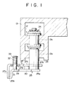
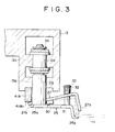
- a horizontal support plate 25a is connected to lower ends of each pair of the connecting rods 23 and has an end portion 25b adapted to support an edge portion of a printed circuit board. Planted on the support plate 25a is a pin 31.
- Each of the clamp plate members 27 in this embodiment has a base portion 27a extending between and protruded from the two rods 23, a first intermediate portion 27c extending from the base portion 27a, a second intermediate portion 27d extending from the first intermediate portion and provided with a through hole 29 which is loosely fitted, and a tip end portion 27b cooperable with the end portion 25b of the support member 25a to clamp a printed circuit board therebetween.
- a spring 32 is provided around the pin 31 and is diposed between the clamp member 27 and a stopper 33 secured to the pin 31 to act on an upper surface of the clamp plate member, so that the clamp member 27 is normally maintained in the close position where the tip end portion 27b of the clamp member 27 is able to be in pressure contact with the upper surface of the printed circuit board supported on the support member 25.
- Designated as 30 is a seating disposed between the support plate 25a and the first intermediate portion 27c of the clamp plate member 27.
- the seating 30 may be fixed to either the support plate member 25 or the clamp plate member 27.
- engaging plates 41A, 41 B, 41 C and 41 D and engaging discs 44 engageable with an upper surface of the base portion of 27a of each of the clamp plate member 27 are provided adjacent to the feed and delivery portions 21 a and 21 b of the conveying path 21.
- the engaging plates 41A-41D have the same structure and, therefore, the following explanation will be made only with respect to the engaging plate 41 B.
- the engaging plate 41 B is fixedly secured to the guide rail 13 and has a lower surface 41 Bb engageable with an upper surface of the base portion 27a of the clamp plate member 27.
- the level of the lower surface 41 Bb of the engaging plate 41 B is so adjusted that when the the lower surface 41 Bb is engaged by the upper surface of the base portion 27a of the clamp plate member 27, the clamp plate member 27 is maintained in the open position.
- a tapered portion 41 Ba is formed to ensure smooth, gradual disengagement or engagement of the clamp plate member 27 from or with the engaging plate 41 B.
- each of the engaging discs 44 is provided on the shaft 43 of each of the sprocket wheels 42 for rotation therewith.
- Each of the engaging disc 44 has a lower surface 44a whose position is adjusted to the same level as that of the lower surface 41 Bb of the eangaging plate 41 B.
- the clamp plate member 27 is maintained in the open position.
- the engaging plates 41 A and 41 C serve to function as guides to permit the engaging discs 44 to be smoothly brought into engagement with the upper portion of the clamp plate members 27, while the engaging plates 41 B and 41 D serve to function as guides for smooth and gradual rocking movement of the clamp clamp plate members 27 to their close positions.
- Fig. 7 designated as 51 is a cleaning station where the tip end portion 27b of the clamp plate member 27 and the end portion 25b of the support member 25a, between which printed wiring boards are to be nipped, are cleaned with any suitable means, such as brushes impregnated with a cleaning liquid.
- any suitable means such as brushes impregnated with a cleaning liquid.
- an engaging plate 41 E is mounted adjacent to the cleaning station to maintain the clamp plate member 27 in the open position in the same manner as described with respect to the engaging plate 41 B.
- the above-described printed circuit board conveying device operates as follows.
- Printed circuit boards are intermittently fed to the feed portion 21 a of the transfer path 21 (Fig. 7).
- the plate members 27 are maintained in the open positions as shown in Fig. 5, thereby to permit the feeding of the printed circuit boards 11 on the end portions 25b of the support members 25.
- the printed circuit board 11 is then transferred in the direction C (Fig. 7) with its opposite side edges being supported on the support members 25.
- the upper surfaces 27a of the clamp plate members 27 are brought into engagement with the lower sufaces 41 Bb of the engaging plates 41 B and then with the tapered portion 41 Ba of the engaging plates 41 B.
- the end portions 27b are brought into contact with the upper surface of the printed circuit board 11 as shown by the two-dotted line in Fig. 3.
- the two side edge portions of the printed circuit board 11 are resiliently clamped between the tip end portions 27b of the clamp plate members 27 and the end portions 25b of the supporting members 25.
- the printed circuit board 11 is conveyed along the transfer path 21 and is soldered in a soldering station (not shown) in a conventional manner.
- the clamp plate members 27 are engaged by the engaging plates 41 c so that the end portions 27b of the clamp members 27 are disengaged from the printed circuit board 11 to permit the release thereof from the end portions 25b of the support plates 25.
- the engagement of the clamp plate members 27 with the engaging plates 41A-41D and the engaging discs 44 is made only in the printed circuit board feed portion 21 a and delivery portion 21 b in the long transfer path 21 so that the torque required for transferring the boards 11 along the path 21 can be reduced in comparison with the conventional device. Additionally, it is no longer necessary to conduct adjustment of the position of engaging plates as required in the conventional device of Figs. 9-11.
Landscapes
- Engineering & Computer Science (AREA)
- Manufacturing & Machinery (AREA)
- Microelectronics & Electronic Packaging (AREA)
- Mechanical Engineering (AREA)
- Chain Conveyers (AREA)
- Molten Solder (AREA)
- Electric Connection Of Electric Components To Printed Circuits (AREA)
Applications Claiming Priority (2)
| Application Number | Priority Date | Filing Date | Title |
|---|---|---|---|
| JP268520/90 | 1990-10-08 | ||
| JP2268520A JPH0794067B2 (ja) | 1990-10-08 | 1990-10-08 | プリント基板の保持搬送方法およびその装置 |
Publications (3)
| Publication Number | Publication Date |
|---|---|
| EP0480585A2 true EP0480585A2 (fr) | 1992-04-15 |
| EP0480585A3 EP0480585A3 (en) | 1993-09-29 |
| EP0480585B1 EP0480585B1 (fr) | 1996-03-27 |
Family
ID=17459662
Family Applications (1)
| Application Number | Title | Priority Date | Filing Date |
|---|---|---|---|
| EP91308346A Expired - Lifetime EP0480585B1 (fr) | 1990-10-08 | 1991-09-12 | Dispositif de transport de plaquettes à circuits imprimés |
Country Status (4)
| Country | Link |
|---|---|
| US (1) | US5145055A (fr) |
| EP (1) | EP0480585B1 (fr) |
| JP (1) | JPH0794067B2 (fr) |
| DE (1) | DE69118301T2 (fr) |
Cited By (6)
| Publication number | Priority date | Publication date | Assignee | Title |
|---|---|---|---|---|
| EP0572878A1 (fr) * | 1992-06-02 | 1993-12-08 | Centrotherm Elektrische Anlagen Gmbh + Co. | Dispositif pour le transport, notamment en ligne droite, de pièces d'éléments ou analogues |
| WO2002090220A1 (fr) * | 2001-05-09 | 2002-11-14 | Serac Group | Pince de prehension de recipients |
| FR2824541A1 (fr) * | 2001-05-09 | 2002-11-15 | Rosebud Consulting Ltd | Dispositif de prehension de recipients et procede de transport correspondant |
| WO2014063394A1 (fr) * | 2012-10-25 | 2014-05-01 | 深圳市劲拓自动化设备股份有限公司 | Structure d'entraînement et dispositif le comprenant |
| WO2015007255A1 (fr) * | 2013-07-17 | 2015-01-22 | Ersa Gmbh | Dispositif de transport de cartes de circuits imprimés |
| WO2019029813A1 (fr) * | 2017-08-10 | 2019-02-14 | Gebr. Schmid Gmbh | Cadre de serrage et dispositif de transport servant au transport de substrats |
Families Citing this family (23)
| Publication number | Priority date | Publication date | Assignee | Title |
|---|---|---|---|---|
| ES2082432T3 (es) * | 1992-09-28 | 1996-03-16 | Ciba Geigy Ag | Procedimiento y dispositivo para el recubrimiento a ambos lados de articulos en forma de placa. |
| DE4337811A1 (de) * | 1993-11-05 | 1995-05-11 | Philips Patentverwaltung | Anordnung zum Transportieren von gedruckten Schaltungsplatten |
| CH690097A5 (fr) * | 1994-05-04 | 2000-04-28 | Bobst Sa | Dispositif d'attache d'une barre de pinces à un train de chaînes au sein d'une machine de traitement d'éléments en plaque. |
| US5562382A (en) * | 1994-07-18 | 1996-10-08 | Kaijo Corporation | Substrate transport apparatus and substrate transport path adjustment method |
| US5553698A (en) * | 1994-12-28 | 1996-09-10 | J And J Container Handling Systems | Conveyor belt apparatus for bottles |
| US5915525A (en) * | 1995-05-01 | 1999-06-29 | International Business Machines Corporation | Parts processing system with notched conveyor belt transport |
| ES2131858T3 (es) * | 1995-09-05 | 1999-08-01 | Europool Srl | Dispositivo de transporte para contenedores provistos de collar sobresaliente, en condicion suspendida. |
| JP3293519B2 (ja) * | 1997-05-22 | 2002-06-17 | 松下電器産業株式会社 | プリント基板の位置決め方法 |
| WO1999003764A1 (fr) * | 1997-07-16 | 1999-01-28 | Systemation Engineered Products, Inc. | Dispositif de manipulation de plateaux |
| DE19930018C2 (de) * | 1999-06-30 | 2001-06-21 | Kuttler Hans Juergen | Vorrichtung zum Transport von flächigen Gegenständen |
| JP3909579B2 (ja) * | 2002-03-19 | 2007-04-25 | 東洋自動機株式会社 | スパウト又はスパウト付き袋のチェーン式搬送装置 |
| DE502006008394D1 (de) * | 2005-09-09 | 2011-01-05 | Sidel Participations Sas | Vorrichtung zum transportieren von gegenständen |
| US20070289843A1 (en) * | 2006-04-18 | 2007-12-20 | Barry Kitazumi | Conveyor System Including Offset Section |
| US7281623B1 (en) | 2006-04-18 | 2007-10-16 | Aquest Systems Corporation | Transport system including vertical rollers |
| US20080053794A1 (en) * | 2006-08-25 | 2008-03-06 | Brain Michael D | Conveyor transfer system |
| US20080050208A1 (en) * | 2006-08-25 | 2008-02-28 | Barry Kitazumi | High speed transporter including horizontal belt |
| DE102007038116A1 (de) * | 2007-07-30 | 2009-02-05 | Gebr. Schmid Gmbh & Co. | Haltemittel, Vorrichtung und Verfahren zum Transport von Substraten, insbesondere Leiterplatten |
| TWM338528U (en) * | 2007-12-21 | 2008-08-11 | Universal Scient Ind Co Ltd | Solder furnace with pressing plate apparatus |
| DE102009018393B4 (de) * | 2009-04-22 | 2017-05-24 | Atotech Deutschland Gmbh | Verfahren, Haltemittel, Vorrichtung und System zum Transportieren eines flächigen Behandlungsgutes und Be- oder Entladeeinrichtung |
| JP6502615B2 (ja) * | 2014-04-11 | 2019-04-17 | 株式会社タムラ製作所 | 搬送加熱装置 |
| FR3049941B1 (fr) * | 2016-04-06 | 2018-04-13 | Saint- Gobain Glass France | Dispositif de convoyage et de maintien pour feuille de verre notamment dans une installation de lavage |
| CN111787781B (zh) * | 2020-06-22 | 2021-12-03 | 赤壁市中亮光电科技有限公司 | 一种贴片led灯珠基板自动焊接装置 |
| TWI827463B (zh) * | 2022-09-02 | 2023-12-21 | 群翊工業股份有限公司 | 直立式夾持基板載具結構 |
Family Cites Families (16)
| Publication number | Priority date | Publication date | Assignee | Title |
|---|---|---|---|---|
| US771641A (en) * | 1903-01-24 | 1904-10-04 | Edward Huber | Straw-stacker. |
| GB1118701A (en) * | 1965-03-30 | 1968-07-03 | Singer Cobble Ltd | Conveyors |
| US3454142A (en) * | 1967-02-27 | 1969-07-08 | John H Holstein | Positive straight line article conveying mechanism |
| US3809210A (en) * | 1972-03-03 | 1974-05-07 | Scandia Packaging Mach | Method and apparatus for conveying a container |
| US4542820A (en) * | 1983-10-28 | 1985-09-24 | Usm Corporation | Conveyor for a substrate |
| US4570785A (en) * | 1984-09-04 | 1986-02-18 | Sommer & Maca Industries, Inc. | Yieldable gripper unit |
| JPS626968U (fr) * | 1985-06-27 | 1987-01-16 | ||
| US4672914A (en) * | 1985-09-13 | 1987-06-16 | Ets Energy Technology Systems Inc. | System for the treatment of edge supported substrates |
| DE3540475A1 (de) * | 1985-11-12 | 1987-05-14 | Siemens Ag | Vorrichtung zum beschicken einer be- und entladeposition einer montageeinrichtung mit einer traegerplatte |
| CH670619A5 (fr) * | 1986-04-29 | 1989-06-30 | Sft Ag Spontanfoerdertechnik | |
| JPS6384980U (fr) * | 1986-11-22 | 1988-06-03 | ||
| NL8702181A (nl) * | 1987-09-14 | 1989-04-03 | Philips Nv | Transportinrichting voor dragers. |
| JPH01133668A (ja) * | 1987-11-20 | 1989-05-25 | Kenji Kondo | プリント基板の保持搬送方法およびその装置 |
| AU2567188A (en) * | 1987-11-30 | 1989-06-01 | Milos Sovak | Hysterography device |
| US4840268A (en) * | 1988-08-23 | 1989-06-20 | Universal Instruments Corporation | Adjustable width chain conveyor |
| NL8901014A (nl) * | 1989-04-21 | 1990-11-16 | Soltec Bv | Geleidingsinrichting voor voorwerpen zoals "printed circuit boards". |
-
1990
- 1990-10-08 JP JP2268520A patent/JPH0794067B2/ja not_active Expired - Fee Related
-
1991
- 1991-09-11 US US07/757,804 patent/US5145055A/en not_active Expired - Lifetime
- 1991-09-12 EP EP91308346A patent/EP0480585B1/fr not_active Expired - Lifetime
- 1991-09-12 DE DE69118301T patent/DE69118301T2/de not_active Expired - Fee Related
Cited By (10)
| Publication number | Priority date | Publication date | Assignee | Title |
|---|---|---|---|---|
| EP0572878A1 (fr) * | 1992-06-02 | 1993-12-08 | Centrotherm Elektrische Anlagen Gmbh + Co. | Dispositif pour le transport, notamment en ligne droite, de pièces d'éléments ou analogues |
| WO2002090220A1 (fr) * | 2001-05-09 | 2002-11-14 | Serac Group | Pince de prehension de recipients |
| FR2824541A1 (fr) * | 2001-05-09 | 2002-11-15 | Rosebud Consulting Ltd | Dispositif de prehension de recipients et procede de transport correspondant |
| US6692050B2 (en) | 2001-05-09 | 2004-02-17 | Serac Group | Receptacle-gripping clamp |
| WO2014063394A1 (fr) * | 2012-10-25 | 2014-05-01 | 深圳市劲拓自动化设备股份有限公司 | Structure d'entraînement et dispositif le comprenant |
| WO2015007255A1 (fr) * | 2013-07-17 | 2015-01-22 | Ersa Gmbh | Dispositif de transport de cartes de circuits imprimés |
| CN104661936A (zh) * | 2013-07-17 | 2015-05-27 | 尔萨有限公司 | 用于印刷电路板的运输设备 |
| US9609794B2 (en) | 2013-07-17 | 2017-03-28 | Ersa Gmbh | Conveyor device for printed circuit boards |
| CN104661936B (zh) * | 2013-07-17 | 2018-09-04 | 尔萨有限公司 | 用于印刷电路板的运输设备 |
| WO2019029813A1 (fr) * | 2017-08-10 | 2019-02-14 | Gebr. Schmid Gmbh | Cadre de serrage et dispositif de transport servant au transport de substrats |
Also Published As
| Publication number | Publication date |
|---|---|
| EP0480585A3 (en) | 1993-09-29 |
| JPH0794067B2 (ja) | 1995-10-11 |
| DE69118301D1 (de) | 1996-05-02 |
| EP0480585B1 (fr) | 1996-03-27 |
| US5145055A (en) | 1992-09-08 |
| JPH04147764A (ja) | 1992-05-21 |
| DE69118301T2 (de) | 1996-10-31 |
Similar Documents
| Publication | Publication Date | Title |
|---|---|---|
| EP0480585B1 (fr) | Dispositif de transport de plaquettes à circuits imprimés | |
| US4681212A (en) | Accumulating conveyor | |
| JPH0238255A (ja) | 折畳まれた印刷用紙の捕集装置 | |
| CA1300547C (fr) | Transporteur duplex | |
| KR0133539B1 (ko) | 보드 형태의 워크피스 처리용 장치 | |
| KR890001848A (ko) | 병 이송장치 | |
| US5301793A (en) | Continuous motion upender | |
| EP1306307B1 (fr) | Dispositif de distribution de couvercles | |
| JP2899332B2 (ja) | ブックブロックの導入装置 | |
| SU625596A3 (ru) | Устройство дл транспортировани в нахлестку листовой печатной продукции | |
| US4681500A (en) | Delivery unit for bookbinding machines | |
| US4390093A (en) | Apparatus for conveying sheets such as veneer having improved wicket construction | |
| JPS6410407B2 (fr) | ||
| CA2240917A1 (fr) | Convoyeur pour charges en porte-a-faux | |
| US4770285A (en) | Conveyor device having a rotatable pallet and device for rotating a pallet | |
| US4118025A (en) | Document conveying means | |
| CN113042947A (zh) | 一种钢丝网架复合保温板生产线及生产方法 | |
| JPS63165265A (ja) | 搬送装置 | |
| KR910004449A (ko) | 종이 장 이송장치 | |
| US4869169A (en) | Apparatus for chain transfer conveyance of sheet printed in a press | |
| JPS59223620A (ja) | リ−ドフレ−ム搬送機構 | |
| US4641829A (en) | Screen printing machine having a stationary printing table | |
| JPH0353209B2 (fr) | ||
| EP0304545B1 (fr) | Appareil pour transférer une plaque lithograpghique | |
| JP2607160B2 (ja) | 片側駆動チェーンコンベヤ |
Legal Events
| Date | Code | Title | Description |
|---|---|---|---|
| PUAI | Public reference made under article 153(3) epc to a published international application that has entered the european phase |
Free format text: ORIGINAL CODE: 0009012 |
|
| AK | Designated contracting states |
Kind code of ref document: A2 Designated state(s): BE DE FR GB IT NL |
|
| PUAL | Search report despatched |
Free format text: ORIGINAL CODE: 0009013 |
|
| AK | Designated contracting states |
Kind code of ref document: A3 Designated state(s): BE DE FR GB IT NL |
|
| 17P | Request for examination filed |
Effective date: 19931214 |
|
| 17Q | First examination report despatched |
Effective date: 19950609 |
|
| GRAH | Despatch of communication of intention to grant a patent |
Free format text: ORIGINAL CODE: EPIDOS IGRA |
|
| GRAA | (expected) grant |
Free format text: ORIGINAL CODE: 0009210 |
|
| AK | Designated contracting states |
Kind code of ref document: B1 Designated state(s): BE DE FR GB IT NL |
|
| PG25 | Lapsed in a contracting state [announced via postgrant information from national office to epo] |
Ref country code: IT Free format text: LAPSE BECAUSE OF FAILURE TO SUBMIT A TRANSLATION OF THE DESCRIPTION OR TO PAY THE FEE WITHIN THE PRE;WARNING: LAPSES OF ITALIAN PATENTS WITH EFFECTIVE DATE BEFORE 2007 MAY HAVE OCCURRED AT ANY TIME BEFORE 2007. THE CORRECT EFFECTIVE DATE MAY BE DIFFERENT FROM THE ONE RECORDED.SCRIBED TIME-LIMIT Effective date: 19960327 Ref country code: FR Effective date: 19960327 Ref country code: BE Effective date: 19960327 Ref country code: NL Free format text: LAPSE BECAUSE OF FAILURE TO SUBMIT A TRANSLATION OF THE DESCRIPTION OR TO PAY THE FEE WITHIN THE PRESCRIBED TIME-LIMIT Effective date: 19960327 |
|
| REF | Corresponds to: |
Ref document number: 69118301 Country of ref document: DE Date of ref document: 19960502 |
|
| EN | Fr: translation not filed | ||
| NLV1 | Nl: lapsed or annulled due to failure to fulfill the requirements of art. 29p and 29m of the patents act | ||
| PLBE | No opposition filed within time limit |
Free format text: ORIGINAL CODE: 0009261 |
|
| STAA | Information on the status of an ep patent application or granted ep patent |
Free format text: STATUS: NO OPPOSITION FILED WITHIN TIME LIMIT |
|
| 26N | No opposition filed | ||
| REG | Reference to a national code |
Ref country code: GB Ref legal event code: IF02 |
|
| PGFP | Annual fee paid to national office [announced via postgrant information from national office to epo] |
Ref country code: GB Payment date: 20060906 Year of fee payment: 16 |
|
| PGFP | Annual fee paid to national office [announced via postgrant information from national office to epo] |
Ref country code: DE Payment date: 20060907 Year of fee payment: 16 |
|
| GBPC | Gb: european patent ceased through non-payment of renewal fee |
Effective date: 20070912 |
|
| PG25 | Lapsed in a contracting state [announced via postgrant information from national office to epo] |
Ref country code: DE Free format text: LAPSE BECAUSE OF NON-PAYMENT OF DUE FEES Effective date: 20080401 |
|
| PG25 | Lapsed in a contracting state [announced via postgrant information from national office to epo] |
Ref country code: GB Free format text: LAPSE BECAUSE OF NON-PAYMENT OF DUE FEES Effective date: 20070912 |