EP0480908A2 - Relais - Google Patents
Relais Download PDFInfo
- Publication number
- EP0480908A2 EP0480908A2 EP91890244A EP91890244A EP0480908A2 EP 0480908 A2 EP0480908 A2 EP 0480908A2 EP 91890244 A EP91890244 A EP 91890244A EP 91890244 A EP91890244 A EP 91890244A EP 0480908 A2 EP0480908 A2 EP 0480908A2
- Authority
- EP
- European Patent Office
- Prior art keywords
- armature
- leg
- yoke
- coil
- shorter
- Prior art date
- Legal status (The legal status is an assumption and is not a legal conclusion. Google has not performed a legal analysis and makes no representation as to the accuracy of the status listed.)
- Granted
Links
- 239000000243 solution Substances 0.000 description 5
- 230000005540 biological transmission Effects 0.000 description 4
- 230000003247 decreasing effect Effects 0.000 description 2
- 238000001746 injection moulding Methods 0.000 description 1
- 230000005415 magnetization Effects 0.000 description 1
- 238000004519 manufacturing process Methods 0.000 description 1
- 239000002184 metal Substances 0.000 description 1
- 238000000034 method Methods 0.000 description 1
Images


Classifications
-
- H—ELECTRICITY
- H01—ELECTRIC ELEMENTS
- H01H—ELECTRIC SWITCHES; RELAYS; SELECTORS; EMERGENCY PROTECTIVE DEVICES
- H01H50/00—Details of electromagnetic relays
- H01H50/16—Magnetic circuit arrangements
- H01H50/18—Movable parts of magnetic circuits, e.g. armature
-
- H—ELECTRICITY
- H01—ELECTRIC ELEMENTS
- H01H—ELECTRIC SWITCHES; RELAYS; SELECTORS; EMERGENCY PROTECTIVE DEVICES
- H01H50/00—Details of electromagnetic relays
- H01H50/16—Magnetic circuit arrangements
- H01H50/36—Stationary parts of magnetic circuit, e.g. yoke
-
- H—ELECTRICITY
- H01—ELECTRIC ELEMENTS
- H01H—ELECTRIC SWITCHES; RELAYS; SELECTORS; EMERGENCY PROTECTIVE DEVICES
- H01H50/00—Details of electromagnetic relays
- H01H50/02—Bases; Casings; Covers
- H01H50/04—Mounting complete relay or separate parts of relay on a base or inside a case
- H01H50/041—Details concerning assembly of relays
- H01H50/042—Different parts are assembled by insertion without extra mounting facilities like screws, in an isolated mounting part, e.g. stack mounting on a coil-support
Definitions
- the invention relates to a relay with a magnet system consisting of a yoke and an armature, in which the armature is mounted on the yoke and a coil, the armature and the yoke engaging with one leg in the coil.
- Such a relay was e.g. known by the EU B1 70 717.
- the yoke consists of two parts with a U-shaped cross section, the legs of which are of unequal length. The longer legs of the yoke are connected to one another on the outside of the coil, the legs of the yoke parts in their connecting area being only half the thickness and lying flat against one another.
- the air gap remaining between them requires a corresponding magnetization, which must be applied by the coil.
- the shorter legs of the two yoke parts engage in the interior of the coil, a relatively large air gap remaining between the mutually facing end faces of the legs of the yoke engaging in the coil.
- the armature is held on a spring and is in the known relay in the dropped state inside the coil on the shorter leg of one part of the yoke with an edge and is dimensioned so that it faces over the edges of the air gap between the two End faces of the two parts of the yoke extends beyond.
- the disadvantage of this known solution is that a total of three air gaps result due to the yoke divided in two, and so on. the yoke between the two parts, and in two places between the yoke and the anchor.
- the magnetic frame consists of three parts that have to be produced accordingly, the reduction in the thickness of the two longer legs in their connection area in particular causing certain problems and costs.
- the assembly of such a relay requires a corresponding assembly effort.
- the object of the invention is to propose a relay of the type mentioned, which is easier to manufacture. Furthermore, the invention has also set itself the task of creating a relay compared to the prior art, which can be realized with a smaller number of individual parts. Another object of the invention can also be that the moving parts have little play.
- the invention is that the armature is L-shaped and is mounted with its shorter leg on the longer leg of the U-shaped, integrally formed yoke running on the outside of the coil, the shorter leg of the yoke engages in the interior of the coil.
- the solution according to the invention also has the advantage of simpler assembly of this relay due to the smaller number of parts. Furthermore, a yoke, as provided according to the invention, can also be produced more easily, since it is only necessary to bend a correspondingly cut sheet metal strip in a U-shape, which is also necessary in the case of the known solution, but with two parts per relay .
- the procedure can be such that the longer leg of the armature is designed as a double-armed lever by being supported on the inner wall of the coil or of the coil body. In this way, it is possible in a simple manner for a normally open contact relay to implement the required armature bearing pressure on the yoke, but in particular there is no need for a separate armature spring.
- the armature is mounted on the yoke with the edge facing away from the end face of the coil.
- the end face of the shorter arm of the armature it is also possible for the end face of the shorter arm of the armature to be curved.
- the armature engages with its shorter leg in a recess of the leg running on the outside of the coil.
- the armature is mounted with its shorter leg in the walls of a housing, with projections projecting laterally from the shorter arm of the armature, which engage in recesses in the walls of the housing.
- This variant has the advantage that no depressions have to be impressed on the yoke, but that they are simply made in the housing produced by injection molding. Due to the protrusions protruding to the side, the game can be kept correspondingly low.
- the shorter leg of the armature has a width which is at least equal to the width of the leg of the yoke running on the outside of the coil, the width of this leg of the yoke being greater than the width of the in the Inside the coil engaging leg of the armature is.
- the armature is pressed with its shorter leg against the leg of the yoke by means of a spring engaging on this and the leg of the yoke located on the outside of the coil.
- the spring is designed as a U-shaped leaf spring which at least partially encompasses the longer leg of the yoke and the shorter leg of the armature.
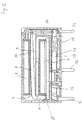
- the yoke 1 is U-shaped, but the leg 3 engaging in the interior of the coil 2 is shorter than the leg 4 running on the outside of the coil 2, the free end of which leg extends over the end face 5 of the coil 2, or its coil former 6 protrudes.
- the leg 3 of the yoke 1 engaging in the coil 2 has a smaller width than the leg 4 running on the outside of the coil 2.
- the armature 7, which is L-shaped, is mounted with its shorter leg 8, the type of mounting being able to be varied.
- the shorter leg 8 of the armature 7 is supported on the yoke 1 with its edge 10 facing away from the end face 5 of the coil 2.
- the longer leg 9 of the armature 7 passes through the interior of the coil 2.
- the width of the longer leg 9 of the armature 7 and the width of the leg 3 of the yoke 1 engaging in the interior of the coil 2 corresponds to the clear width of the interior of the coil, wherein of course, a corresponding game is provided.
- the shorter leg 8 has a width exceeding the width of the longer leg 9, which corresponds to that of the width of the longer leg 4 of the yoke 1 extending on the outside of the coil 2.
- a corresponding transmission element for actuating the contact spring set, not shown in FIG. 1, can act on the region of the longer leg 9 of the armature 7 which has a smaller thickness.
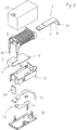
- the armature 7 is provided with projections 11 projecting laterally from its shorter leg 8 formed with cambered end faces 25, which are arranged coaxially with one another and engage in recesses 12 of a housing 13 partially surrounding the coil 2, at which the reels of the coil 2 are passed laterally and are connected to connecting pins 14.
- the contact spring set 17, also provided with connecting pins 16, is held in a frame 18 connected to the housing 13.
- the movable contact spring 19 is actuated by means of a transmission element 20 which engages in bores of the armature 7. Furthermore, a cover 21 surrounding the relay is provided.
- the longer leg 9 of the armature 7 is supported on the inner wall of the coil 2 or the coil body; the support point represents a pivot point 22.
- Such a longer leg 9 of the armature 7 is designed as a double-armed lever.
- the shorter leg 8 with lateral projections is mounted in the housing 13.
- FIG. 4 shows a further variant of the mounting of the armature 7 on the yoke 1.
- a depression 23 is arranged near the free end of this leg 4, into which the shorter leg 8 of the anchor engages, the end face of the shorter leg 8 is convex.
- the armature 7 is pressed by means of a U-shaped leaf spring 24 against the yoke 1, which engages around the longer leg 4 of the yoke 1 and the shorter leg 8 of the armature 7 and is simply attached to these two parts .
- This type of bearing is particularly suitable for relays with changeover contacts.
- the longer leg 4 of the yoke which extends on the outside of the coil, has a width which corresponds to the width of the coil 2, the shorter leg 8 of the armature also having this width.
- the shorter legs of the yoke 1 and the armature 7 have a width which enables these parts to be inserted into the interior of the coil 2.
- the longer leg 9 has a decreasing thickness in the region near its free end, the thickness of the longer leg 9 decreasing progressively in the relay according to FIG. 2, whereas in the relay according to FIG. 3, the thickness is reduced in stages of the leg 9 is given.
Landscapes
- Physics & Mathematics (AREA)
- Electromagnetism (AREA)
- Electromagnets (AREA)
Applications Claiming Priority (2)
| Application Number | Priority Date | Filing Date | Title |
|---|---|---|---|
| AT206690A AT408928B (de) | 1990-10-12 | 1990-10-12 | Relais |
| AT2066/90 | 1990-10-12 |
Publications (3)
| Publication Number | Publication Date |
|---|---|
| EP0480908A2 true EP0480908A2 (fr) | 1992-04-15 |
| EP0480908A3 EP0480908A3 (en) | 1993-03-17 |
| EP0480908B1 EP0480908B1 (fr) | 1996-07-10 |
Family
ID=3527047
Family Applications (1)
| Application Number | Title | Priority Date | Filing Date |
|---|---|---|---|
| EP91890244A Expired - Lifetime EP0480908B1 (fr) | 1990-10-12 | 1991-10-11 | Relais |
Country Status (4)
| Country | Link |
|---|---|
| EP (1) | EP0480908B1 (fr) |
| AT (1) | AT408928B (fr) |
| DE (1) | DE59107988D1 (fr) |
| ES (1) | ES2089178T3 (fr) |
Cited By (3)
| Publication number | Priority date | Publication date | Assignee | Title |
|---|---|---|---|---|
| US6608542B2 (en) | 2001-08-10 | 2003-08-19 | Tyco Electronics Amp Gmbh | Switching relay with improved armature spring |
| CN112262452A (zh) * | 2018-04-24 | 2021-01-22 | 菲尼克斯电气公司 | 继电器 |
| CN112271120A (zh) * | 2020-10-31 | 2021-01-26 | 中韶电气股份有限公司 | 减少空间占用的小型断路器的磁系统 |
Families Citing this family (1)
| Publication number | Priority date | Publication date | Assignee | Title |
|---|---|---|---|---|
| DE10300036B4 (de) * | 2002-01-12 | 2009-08-13 | Tyco Electronics Amp Gmbh | Magnetsystem, insbesondere für ein elektromagnetisches Relais |
Family Cites Families (9)
| Publication number | Priority date | Publication date | Assignee | Title |
|---|---|---|---|---|
| DE2813822C2 (de) * | 1978-03-31 | 1982-11-18 | Rausch & Pausch, 8672 Selb | Elektromagnetisches Schaltrelais |
| DE3008295A1 (de) * | 1980-01-22 | 1981-09-24 | Mecanismos Auxiliares Industriales, S.A. M.A.I.S.A., Valls, Tarragona | Klappankerrelais |
| CA1162218A (fr) * | 1981-04-06 | 1984-02-14 | Sds Elektro Gmbh | Relais electromagnetique |
| DE3303666A1 (de) * | 1983-02-03 | 1984-08-09 | Hans 8024 Deisenhofen Sauer | Relais mit wenigstens einem, innerhalb des spulenkoerpers schwenkbeweglich gelagerten anker |
| US4689587A (en) * | 1985-05-22 | 1987-08-25 | Siemens Aktiengesellschaft | Electromagnetic relay |
| DE3518397A1 (de) * | 1985-05-22 | 1986-11-27 | Siemens AG, 1000 Berlin und 8000 München | Lageranordnung fuer den anker eines elektromagnetischen relais |
| US4720694A (en) * | 1985-05-22 | 1988-01-19 | Siemens Aktiengesellschaft | Electromagnetic relay |
| US4879536A (en) * | 1987-09-30 | 1989-11-07 | Anritsu Corporation | Electromagnetic relay |
| JPH0733344Y2 (ja) * | 1988-12-23 | 1995-07-31 | 松下電工株式会社 | 電磁継電器 |
-
1990
- 1990-10-12 AT AT206690A patent/AT408928B/de not_active IP Right Cessation
-
1991
- 1991-10-11 ES ES91890244T patent/ES2089178T3/es not_active Expired - Lifetime
- 1991-10-11 DE DE59107988T patent/DE59107988D1/de not_active Expired - Lifetime
- 1991-10-11 EP EP91890244A patent/EP0480908B1/fr not_active Expired - Lifetime
Cited By (4)
| Publication number | Priority date | Publication date | Assignee | Title |
|---|---|---|---|---|
| US6608542B2 (en) | 2001-08-10 | 2003-08-19 | Tyco Electronics Amp Gmbh | Switching relay with improved armature spring |
| CN112262452A (zh) * | 2018-04-24 | 2021-01-22 | 菲尼克斯电气公司 | 继电器 |
| CN112262452B (zh) * | 2018-04-24 | 2023-09-15 | 菲尼克斯电气公司 | 继电器 |
| CN112271120A (zh) * | 2020-10-31 | 2021-01-26 | 中韶电气股份有限公司 | 减少空间占用的小型断路器的磁系统 |
Also Published As
| Publication number | Publication date |
|---|---|
| DE59107988D1 (de) | 1996-08-14 |
| ES2089178T3 (es) | 1996-10-01 |
| EP0480908A3 (en) | 1993-03-17 |
| AT408928B (de) | 2002-04-25 |
| ATA206690A (de) | 2001-08-15 |
| EP0480908B1 (fr) | 1996-07-10 |
Similar Documents
| Publication | Publication Date | Title |
|---|---|---|
| EP0203515B1 (fr) | Relais électromagnétique | |
| DE102006036613B3 (de) | Relais mit einer Konkaktanordnung aus Kontaktfedern | |
| EP0022953B1 (fr) | Relais électromagnétique | |
| DE3132239C2 (de) | Elektromagnetisches Relais | |
| DE2541650C3 (de) | Miniaturrelais | |
| EP0707331B1 (fr) | Relais | |
| EP0222243A1 (fr) | Relais électromagnétique | |
| DE2719870C2 (de) | Relais, insbesondere Flachrelais und zur Verwendung in gedruckten Schaltungen | |
| EP0480908B1 (fr) | Relais | |
| EP1473752B1 (fr) | Déclencheur électromagnétique | |
| EP0091687A1 (fr) | Relais électromagnétique | |
| EP0015389B1 (fr) | Relais miniature disposé dans un boîtier | |
| EP0098480A1 (fr) | Relais électromagnétique avec un dispositif indicateur mécanique pour la position de l'armature | |
| DE3415761A1 (de) | Elektromagnetisches relais | |
| EP0198492A2 (fr) | Relais électromagnétique polarisé | |
| EP0375732A1 (fr) | Dispositif de verrouillage pour appareil de coupure a commande electromagnetique | |
| DE2402236C3 (de) | Steckbares, mit einem quaderförmigen Gehäuse versehenes, elektromagnetisches Relais | |
| AT404766B (de) | Relais | |
| EP0795186B1 (fr) | Commutateur electromagnetique | |
| DE1934624B2 (de) | Elektromagnetisches Relais | |
| DE3328684C1 (de) | Ankerhaltefeder für DIL-Relais | |
| DE2625203A1 (de) | Polarisiertes elektromagnetisches relais | |
| EP0068391A2 (fr) | Relais electromagnétique polarisé miniaturisé | |
| DE4235981A1 (de) | Elektrischer Schalter | |
| AT388468B (de) | Relais |
Legal Events
| Date | Code | Title | Description |
|---|---|---|---|
| PUAI | Public reference made under article 153(3) epc to a published international application that has entered the european phase |
Free format text: ORIGINAL CODE: 0009012 |
|
| AK | Designated contracting states |
Kind code of ref document: A2 Designated state(s): CH DE ES FR GB IT LI SE |
|
| PUAL | Search report despatched |
Free format text: ORIGINAL CODE: 0009013 |
|
| AK | Designated contracting states |
Kind code of ref document: A3 Designated state(s): CH DE ES FR GB IT LI SE |
|
| 17P | Request for examination filed |
Effective date: 19930823 |
|
| 17Q | First examination report despatched |
Effective date: 19940907 |
|
| GRAH | Despatch of communication of intention to grant a patent |
Free format text: ORIGINAL CODE: EPIDOS IGRA |
|
| GRAH | Despatch of communication of intention to grant a patent |
Free format text: ORIGINAL CODE: EPIDOS IGRA |
|
| GRAA | (expected) grant |
Free format text: ORIGINAL CODE: 0009210 |
|
| AK | Designated contracting states |
Kind code of ref document: B1 Designated state(s): CH DE ES FR GB IT LI SE |
|
| REG | Reference to a national code |
Ref country code: CH Ref legal event code: NV Representative=s name: SIEMENS SCHWEIZ AG |
|
| REF | Corresponds to: |
Ref document number: 59107988 Country of ref document: DE Date of ref document: 19960814 |
|
| REG | Reference to a national code |
Ref country code: ES Ref legal event code: FG2A Ref document number: 2089178 Country of ref document: ES Kind code of ref document: T3 |
|
| ITF | It: translation for a ep patent filed | ||
| ET | Fr: translation filed | ||
| REG | Reference to a national code |
Ref country code: ES Ref legal event code: FG2A Ref document number: 2089178 Country of ref document: ES Kind code of ref document: T3 |
|
| GBT | Gb: translation of ep patent filed (gb section 77(6)(a)/1977) |
Effective date: 19970120 |
|
| PLBE | No opposition filed within time limit |
Free format text: ORIGINAL CODE: 0009261 |
|
| STAA | Information on the status of an ep patent application or granted ep patent |
Free format text: STATUS: NO OPPOSITION FILED WITHIN TIME LIMIT |
|
| 26N | No opposition filed | ||
| REG | Reference to a national code |
Ref country code: CH Ref legal event code: PFA Free format text: EH - SCHRACK COMPONENTS-AKTIENGESELLSCHAFT TRANSFER- TYCO ELECTRONICS GMBH Ref country code: CH Ref legal event code: NV Representative=s name: RIEDERER HASLER & PARTNER PATENTANWAELTE AG |
|
| PGFP | Annual fee paid to national office [announced via postgrant information from national office to epo] |
Ref country code: SE Payment date: 20001004 Year of fee payment: 10 |
|
| PG25 | Lapsed in a contracting state [announced via postgrant information from national office to epo] |
Ref country code: SE Free format text: LAPSE BECAUSE OF NON-PAYMENT OF DUE FEES Effective date: 20011012 |
|
| REG | Reference to a national code |
Ref country code: GB Ref legal event code: 732E |
|
| REG | Reference to a national code |
Ref country code: GB Ref legal event code: IF02 |
|
| EUG | Se: european patent has lapsed |
Ref document number: 91890244.6 |
|
| PGFP | Annual fee paid to national office [announced via postgrant information from national office to epo] |
Ref country code: CH Payment date: 20031219 Year of fee payment: 13 |
|
| PG25 | Lapsed in a contracting state [announced via postgrant information from national office to epo] |
Ref country code: CH Free format text: LAPSE BECAUSE OF NON-PAYMENT OF DUE FEES Effective date: 20041031 Ref country code: LI Free format text: LAPSE BECAUSE OF NON-PAYMENT OF DUE FEES Effective date: 20041031 |
|
| REG | Reference to a national code |
Ref country code: CH Ref legal event code: PL |
|
| PGFP | Annual fee paid to national office [announced via postgrant information from national office to epo] |
Ref country code: FR Payment date: 20101105 Year of fee payment: 20 |
|
| PGFP | Annual fee paid to national office [announced via postgrant information from national office to epo] |
Ref country code: DE Payment date: 20101027 Year of fee payment: 20 |
|
| PGFP | Annual fee paid to national office [announced via postgrant information from national office to epo] |
Ref country code: GB Payment date: 20101025 Year of fee payment: 20 Ref country code: IT Payment date: 20101027 Year of fee payment: 20 |
|
| PGFP | Annual fee paid to national office [announced via postgrant information from national office to epo] |
Ref country code: ES Payment date: 20101026 Year of fee payment: 20 |
|
| REG | Reference to a national code |
Ref country code: DE Ref legal event code: R071 Ref document number: 59107988 Country of ref document: DE |
|
| REG | Reference to a national code |
Ref country code: DE Ref legal event code: R071 Ref document number: 59107988 Country of ref document: DE |
|
| REG | Reference to a national code |
Ref country code: GB Ref legal event code: PE20 Expiry date: 20111010 |
|
| PG25 | Lapsed in a contracting state [announced via postgrant information from national office to epo] |
Ref country code: GB Free format text: LAPSE BECAUSE OF EXPIRATION OF PROTECTION Effective date: 20111010 |
|
| PG25 | Lapsed in a contracting state [announced via postgrant information from national office to epo] |
Ref country code: DE Free format text: LAPSE BECAUSE OF EXPIRATION OF PROTECTION Effective date: 20111012 |
|
| REG | Reference to a national code |
Ref country code: ES Ref legal event code: FD2A Effective date: 20130801 |
|
| PG25 | Lapsed in a contracting state [announced via postgrant information from national office to epo] |
Ref country code: ES Free format text: LAPSE BECAUSE OF EXPIRATION OF PROTECTION Effective date: 20111012 |