EP0481090B1 - In der form etikettierter behälter und dessen herstellung - Google Patents
In der form etikettierter behälter und dessen herstellung Download PDFInfo
- Publication number
- EP0481090B1 EP0481090B1 EP91908634A EP91908634A EP0481090B1 EP 0481090 B1 EP0481090 B1 EP 0481090B1 EP 91908634 A EP91908634 A EP 91908634A EP 91908634 A EP91908634 A EP 91908634A EP 0481090 B1 EP0481090 B1 EP 0481090B1
- Authority
- EP
- European Patent Office
- Prior art keywords
- label
- container
- side wall
- mold
- wall sections
- Prior art date
- Legal status (The legal status is an assumption and is not a legal conclusion. Google has not performed a legal analysis and makes no representation as to the accuracy of the status listed.)
- Expired - Lifetime
Links
Images




Classifications
-
- B—PERFORMING OPERATIONS; TRANSPORTING
- B65—CONVEYING; PACKING; STORING; HANDLING THIN OR FILAMENTARY MATERIAL
- B65D—CONTAINERS FOR STORAGE OR TRANSPORT OF ARTICLES OR MATERIALS, e.g. BAGS, BARRELS, BOTTLES, BOXES, CANS, CARTONS, CRATES, DRUMS, JARS, TANKS, HOPPERS, FORWARDING CONTAINERS; ACCESSORIES, CLOSURES, OR FITTINGS THEREFOR; PACKAGING ELEMENTS; PACKAGES
- B65D25/00—Details of other kinds or types of rigid or semi-rigid containers
- B65D25/34—Coverings or external coatings
- B65D25/36—Coverings or external coatings formed by applying sheet material
-
- B—PERFORMING OPERATIONS; TRANSPORTING
- B29—WORKING OF PLASTICS; WORKING OF SUBSTANCES IN A PLASTIC STATE IN GENERAL
- B29C—SHAPING OR JOINING OF PLASTICS; SHAPING OF MATERIAL IN A PLASTIC STATE, NOT OTHERWISE PROVIDED FOR; AFTER-TREATMENT OF THE SHAPED PRODUCTS, e.g. REPAIRING
- B29C45/00—Injection moulding, i.e. forcing the required volume of moulding material through a nozzle into a closed mould; Apparatus therefor
- B29C45/14—Injection moulding, i.e. forcing the required volume of moulding material through a nozzle into a closed mould; Apparatus therefor incorporating preformed parts or layers, e.g. injection moulding around inserts or for coating articles
-
- B—PERFORMING OPERATIONS; TRANSPORTING
- B29—WORKING OF PLASTICS; WORKING OF SUBSTANCES IN A PLASTIC STATE IN GENERAL
- B29C—SHAPING OR JOINING OF PLASTICS; SHAPING OF MATERIAL IN A PLASTIC STATE, NOT OTHERWISE PROVIDED FOR; AFTER-TREATMENT OF THE SHAPED PRODUCTS, e.g. REPAIRING
- B29C45/00—Injection moulding, i.e. forcing the required volume of moulding material through a nozzle into a closed mould; Apparatus therefor
- B29C45/14—Injection moulding, i.e. forcing the required volume of moulding material through a nozzle into a closed mould; Apparatus therefor incorporating preformed parts or layers, e.g. injection moulding around inserts or for coating articles
- B29C45/14467—Joining articles or parts of a single article
- B29C45/14475—Joining juxtaposed parts of a single article, e.g. edges of a folded container blank
-
- B—PERFORMING OPERATIONS; TRANSPORTING
- B29—WORKING OF PLASTICS; WORKING OF SUBSTANCES IN A PLASTIC STATE IN GENERAL
- B29C—SHAPING OR JOINING OF PLASTICS; SHAPING OF MATERIAL IN A PLASTIC STATE, NOT OTHERWISE PROVIDED FOR; AFTER-TREATMENT OF THE SHAPED PRODUCTS, e.g. REPAIRING
- B29C45/00—Injection moulding, i.e. forcing the required volume of moulding material through a nozzle into a closed mould; Apparatus therefor
- B29C45/14—Injection moulding, i.e. forcing the required volume of moulding material through a nozzle into a closed mould; Apparatus therefor incorporating preformed parts or layers, e.g. injection moulding around inserts or for coating articles
- B29C2045/1486—Details, accessories and auxiliary operations
- B29C2045/14901—Coating a sheet-like insert smaller than the dimensions of the adjacent mould wall
- B29C2045/14918—Coating a sheet-like insert smaller than the dimensions of the adjacent mould wall in-mould-labelling
-
- B—PERFORMING OPERATIONS; TRANSPORTING
- B29—WORKING OF PLASTICS; WORKING OF SUBSTANCES IN A PLASTIC STATE IN GENERAL
- B29C—SHAPING OR JOINING OF PLASTICS; SHAPING OF MATERIAL IN A PLASTIC STATE, NOT OTHERWISE PROVIDED FOR; AFTER-TREATMENT OF THE SHAPED PRODUCTS, e.g. REPAIRING
- B29C45/00—Injection moulding, i.e. forcing the required volume of moulding material through a nozzle into a closed mould; Apparatus therefor
- B29C45/14—Injection moulding, i.e. forcing the required volume of moulding material through a nozzle into a closed mould; Apparatus therefor incorporating preformed parts or layers, e.g. injection moulding around inserts or for coating articles
- B29C2045/1486—Details, accessories and auxiliary operations
- B29C2045/14934—Preventing penetration of injected material between insert and adjacent mould wall
-
- B—PERFORMING OPERATIONS; TRANSPORTING
- B29—WORKING OF PLASTICS; WORKING OF SUBSTANCES IN A PLASTIC STATE IN GENERAL
- B29C—SHAPING OR JOINING OF PLASTICS; SHAPING OF MATERIAL IN A PLASTIC STATE, NOT OTHERWISE PROVIDED FOR; AFTER-TREATMENT OF THE SHAPED PRODUCTS, e.g. REPAIRING
- B29C45/00—Injection moulding, i.e. forcing the required volume of moulding material through a nozzle into a closed mould; Apparatus therefor
- B29C45/0046—Details relating to the filling pattern or flow paths or flow characteristics of moulding material in the mould cavity
-
- B—PERFORMING OPERATIONS; TRANSPORTING
- B65—CONVEYING; PACKING; STORING; HANDLING THIN OR FILAMENTARY MATERIAL
- B65D—CONTAINERS FOR STORAGE OR TRANSPORT OF ARTICLES OR MATERIALS, e.g. BAGS, BARRELS, BOTTLES, BOXES, CANS, CARTONS, CRATES, DRUMS, JARS, TANKS, HOPPERS, FORWARDING CONTAINERS; ACCESSORIES, CLOSURES, OR FITTINGS THEREFOR; PACKAGING ELEMENTS; PACKAGES
- B65D2203/00—Decoration means, markings, information elements, contents indicators
- B65D2203/02—Labels
Definitions
- the present invention relates to a label for use in making in-mold labelled containers and a method for making such containers.
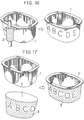
- the direct printing method is to roll a printing roller (2) directly on the side wall of the container (1) as illustrated by Fig. 16.
- the shrink wrapping method is to wrap the container (1) with shrinkable film (3) as illustrated by Fig. 17, and the label adhering method is to stick a printed label (4) on the container (1) as illustrated by Fig. 18, respectively of the attached drawings.
- the direct printing method as illustrated by Fig. 16 is disadvantageously poor in its expressive effect
- the shrink wrapping method as illustrated by Fig. 17 required a secondary process with a result of increased costs
- the label adhering method as illustrated by Fig. 18 also requires a secondary process and correspondingly increases costs.
- the conventional in-mold labelling method for the injection molded container is generally to load a label (7) comprising a bottom wall section (5) and side wall sections (6) into an injection mold and then to effectuate desired labelling with injected resin, as illustrated by Fig. 19.
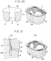
- the alternative method is als well known, according to which the opposite side edges (6a), (6a) of the label (7) are joined to each other with synthetic resin as illustrated by Fig. 20.
- the in-mold labelling method is advantageous, since the labelling and the container molding are performed simultaneously. No secondary process is required.
- the conventional in-mold labelling method is accompanied with unsolved problems.
- the conventional method of in-mold labelling has been effective for a cubic container having a side wall consisting of plane surfaces as seen in Fig. 19, but ineffective for a container with a curved side wall.
- the conventional method of in-mold labelling it has been difficult for the conventional method of in-mold labelling to achieve the labelling on respective projecting legs for structural reasons.
- a flow of injected resin as indicated by arrows occurs in the proximities of respective curved corners during flowing from a passage (10) to a passage (11) both defined between a core (8) and a cavity (9) of the mold. Consequently, a partial quantity of injected resin is apt to the forced out onto an outer surface of the label's side wall (6), because a lower end (6E) of the label's side wall (6) is at a level higher than the container's bottom (1B) in the proximities of the respective curved corners of the container (1).
- a part of the injected resin hs often been forced out onto the outer surface of the label or the label has often been creased with wrinkles.
- a label and a method for insertion molding labelled containers is known (GB 2 190 620 A), where the label is prepared having a series of spaced slits along fold lines linking base and wall portions thereof.
- the disadvantages described above will also appear with this known label and method.
- the present invention provides a label for use in making in-mold labelled containers and to be labelled on the outer side of the container's curved side wall, wherein said label has a configuration comprising:
- a surface of the mold core with the container's bottom may be provided with grooves or the like serving to direct or guide a flow of injected resin so as to form thickened areas extending along the respective label folds or along the inner surface of container's bottom.
- An important feature of the invention lies in that the label and the method facilitate a smooth flow of injection resin in the proximiteis of said boundaries. Another important feature lies in that the core or the cavity is formed with grooves or the like for positively guiding the flow of injected resin.
- the label is forced by the flow of injected resin against the cavity side of the mod and no quantity of injected resin is forced out onto the outer side of the label.
- a pair of the label's side wall sections (6) are connected by a corresponding pair of connector bands (12) integrally with a label's bottom wall section (5).
- Each of the label's side wall sections (6) are fan-shaped.
- the label's side wall section (6) is provided with cuts (13) extending along extensions of opposite side edges of the associated connector band (12).
- the side wall section (6) with a folding line (14) connecting forward ends of the respective cuts (13) or with cutouts (15) intermittently arranged on an imaginary line corresponding to said folding line or with both said fording line (14) and said cutouts (15).
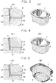
- Figs. 3 through 5 illustrate by way of example how the side wall of the container (1) is molded adjacent each curved corner.
- the container (1) is legged and the curved corner is constructed so that the label's side wall section (6) extends downward beyond a bottom (1B) of the container (1) to a lower end (6E) and injected resin flowing from a passage (10) to a passage (11) is guided by the label's side wall section (6) as indicated by arrows. In this manner, no quantity of injected resin is forces out onto the outer surface of the label.
- Such arrangement corresponds to an improvement of the conventional arrangement shown by Fig. 21.
- a depth of the cuts (13) may be appropriately adjusted to accommodate the case of a legless container.
- the container 1 is legless and the cavity side is formed in the proximity of each curved corner with a downward slope (16) at which the passage (10) and the passage (11) intersect each other.
- the label's side wall section (6) extends downward beyond the container's bottom (1B) to the lower end (6E) and thereby the lower end (6E) of the label is stabilized on the cavity side.
- Fig. 5 here is also shown a legless container but the cavity is formed in the proximity of each curved corner with a projection (17) having a triangular cross-section.
- the core (8) is correspondingly provided with an upwardly slanting cut surface (17a).
- injected resin is guided by the label as indicated by arrows and the label is tightly stabilized against the cavity side even when the lower end (6E) of the label is at a level above the container's bottom (1B).
- Fig. 5(B) shows the bottom of the container molded in the manner as has been described above.
- Reference numeral (18) designates grooves formed by the respective triangular cross-sectioned projections (17).
- the label (7) is erected by folding the label's side wall sections (6) upwardly along the folding lines (14) or the lines on which the cutouts (15) are intermittently arranged as shown by Fig. 1(B), then the erected label is loaded into the mold with the label's bottom wall section (5) ahead and injection resin is introduced into a space defined between the core and the cavity of the mold. Injected resin flows along label's bottom wall section (5) as indicated by the arrows in Fig. 2(A) and (B) and around each curved corner as indicated by the arrows in Fig. 3(A).
- the core and the cavity are opened, and then the developed label is forced into the cavity so as to be folded closely against the inner wall of the cavity. Resin injected into the space between the core (8) and the cavity (9) is unified with the label, allowing the label to be tightly bonded to the outer side of the container's side wall consisting of plane and curved surfaces.
- the cuts (13) and the cutouts (15) effectively function not only to prevent the label from being creased with wrinkles but also to prevent injected resin from flowing into a space which otherwise would be formed between the cavity and the label. Provision of the cutouts (15) facilitates the label to be folded.
- the injection molded container of the invention may be made from soft or hard thermoplastic synthetic resin such as polypropylene (PP), polyethylene (PE), polystyrene (PS) and polyester (PET), and the container may present various cross-sectional shapes such as square, rectangular, circular, oval and polygonal shapes.
- soft or hard thermoplastic synthetic resin such as polypropylene (PP), polyethylene (PE), polystyrene (PS) and polyester (PET)
- PP polypropylene
- PE polyethylene
- PS polystyrene
- PET polyester
- the container may present various cross-sectional shapes such as square, rectangular, circular, oval and polygonal shapes.
- the label for molding of the in-mold labeled container may be of normal paper (inclusive of newspaper), coated paper, plastic film, synthetic paper or the like so far as a label cut out from such material can be maintained in its folded condition.
- the printed label of such material is previously cut out into a configuration having given bottom wall section and side wall sections so as to be properly loaded into a mold of a predetermined configuration defined by a combination of plane and curved surfaces.
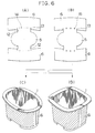
- FIG. 6 there is illustrated an embodiment of two-way label to be used with a legged container.
- Fig. 6(A) shows a two-way label provided with the folding lines (14) and the cuts (13), which is used for molding of an in-mold labelled container as shown by Fig. 6(C) or (D).
- Fig. 6(C) shows an oblong container in-mold labeled with such two-way label and
- Fig. 6(D) shows a cubic container in-mold labelled with such two-way label.
- Fig. 6(B) shows a two-way label provided with the cutouts (15) and the cuts (13), which is used for molding of said in-mold labeled container as shown by Fig. 6(C) or (D).
- the specific embodiment shown by Fig. 6(B) employs the diamond-shaped cutouts (15).
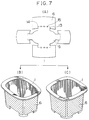
- FIG. 7 there is illustrated an embodiment of four-way label to be used with a legged container, which is provided with the cuts (13), the folding lines (14) and the cutouts (15).
- Fig. 7(B) shows an oblong container in-mold labeled with such four-way label
- Fig. 7(C) shows a cubic container in-mold labelled with such four-way label.
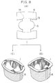
- Figs. 8 and 9 illustrate embodiments of the label both to be used with a legless container.
- Fig. 8(A) shows a two-way label provided with the folding lines (14) and the cuts (13), which is used to obtain an in-mold labelled container as shown by Fig. 8(C) or (D).
- Fig. 8(C) shows an oblong container in-mold labeled with such two-way label and
- Fig. 8(D) shows a cubic container in-mold labelled with such two-way label.
- Fig. 8(B) shows a two-way label provided with the cutouts (15) and the cuts (13) to be used to obtain an in-mold labelled container as shown by Fig. 8(E) or (F).
- Fig. 8(E) shows an oblong container in-mold labeled with such two-way label
- Fig. 8(F) shows a cubic container in-mold labelled with such two-way label.
- Fig. 9 illustrates an embodiment of four-way label to be used with a legless container, which is provided, as shown by Fig. 9(A), with the cutouts (15), the folding lines (14) and the cuts (13).
- Fig. 9(B) shows an oblong container in-mold labeled with such four-way label and Fig. 9(C) shows a cubic container in-mold labeled with such four-way label.
- the core (8) is provided with a suitable groove to assure that resin injected through the inlet port is preferentially directed to the inner side of the label.
- the core (8) may be formed with a single linear groove (18) as shown by Fig. 10(A) or a cross-shaped groove (19) as shown by Fig. 10(B) to achieve positive supply of resin to the inner side of the label and thereby to mold the label on the curved outer side of the container with a high stability.
- Fig. 12 In order to direct the flow of resin injected through the inlet port into the mold preferentially toward the inner side of the label, there is available another measure as illustrated by Fig. 12, according to which the areas of the label to be folded are made thicker than the rest so that injected resin may force the label's side wall from the inner side thereof against the cavity side along said thicker areas. The label can be thereby forced tightly against the cavity side for properly molding the label on the curved outer side of the container.
- reference numeral (20) designates cut surfaces provided in the core (8) to form the above-mentioned thicker areas and reference numeral (21) in Fig. 13 designates these thicker areas. Such arrangement promotes injected resin to flow along the cut surfaces (20) of the core (8).
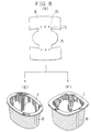
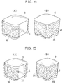
- Fig. 14(A) illustrates a relationship between the core (8) and the two-way label (6), said core having the single linear groove (18) provided at respective ends with cut surfaces
- Fig. 14 (B) illustrates a relationship between the core (8) and the four-way label (6), said core having the cross-shaped groove (19) provided at respective ends with cut surfaces. These cut surfaces are useful for positively directing injected resin toward the inner side of the label.
- Fig. 15(A) and (B) illustrate a relationship between the core (8) and the label (6) by indicating the resin flow occurring in the arrangement of Fig. 14(A) and (B), respectively.
- the core side of the mold is preferably provided at locations corresponding to the bottom and side walls of the container with the grooves and the cut surfaces serving to control the resin flow so that the label to be prevented from being creased with wrinkles may be properly molded on the outer sur face of the container's side wall during injection of resin into the mold.
- the method of the present invention causes the flow of injected resin to force the label tightly against the cavity side and thereby allows the outer side of the container's side wall to be provided over the areas comprising the curved surfaces alone or comprising both the curved and plane surfaces with the desired in-mold labeling. It should be understood, however, that the invention is not limited to the specific embodiments as have been described and illustrated hereinabove.
- the present invention provides the container so arranged that the label may be forced by the flow of injected resin tightly against the cavity side of the mold and thereby the outer side of the container's side wall may be provided on the areas comprising the curved surfaces alone or comprising both the curved and plane surfaces with the desired in-mold labelling.
- the invention is applicable to various types of container, for example, those for foodstuffs and particularly useful for the containers for commodities to be provided with the content indication or the illustration so that these commodities may be easily discriminated from the other commodities.
Landscapes
- Engineering & Computer Science (AREA)
- Mechanical Engineering (AREA)
- Manufacturing & Machinery (AREA)
- Injection Moulding Of Plastics Or The Like (AREA)
- Moulds For Moulding Plastics Or The Like (AREA)
Claims (9)
- Etikett (7) zur Verwendung in der Herstellung von in der Eingußform ("in-mold") etikettierten Behältern (1) und zur Etikettierung an der Außenseite der gewölbten Wand des Behälters, wobei genanntes Etikett eine Konfiguration hat, die folgendes umfasst:- einen unteren Wandabschnitt (5)- seitliche Wandabschnitte (6)- Falzlinien (14) und/oder in Abständen angeordnete Ausschnitte (15), die sich zwischen genanntem unteren Wandabschnitt (5) und den seitlichen Wandabschnitten (6) erstrecken, und
dadurch gekennzeichnet sind, daß- genannte Falzlinien (14) und/oder in Abständen angeordnete Ausschnitte (15), so positioniert sind, daß sie eine Entfernung zu den Randteilen (6E) der seitlichen Wandabschnitte (6), die angrenzend an den unteren Wandabschnitt (5) liegen, aufweisen,- Schnitte (13), die im Etikett (7) so ausgeformt sind, daß sie sich senkrecht von genannten Falzlinien (14) in Richtung der genannten unteren Teile (5) hin zu genannten Randteilen (6E) der seitlichen Wandabschnitte (6) erstrecken,- die Randteile (6E) der seitlichen Wandabschnitte (6) sich über den unteren Wandabschnitt (5) des Etikettes erstrecken, wenn das Etikett zur Verwendung in der Form gefaltet ist. - Etikett nach Anspruch 1, dadurch gekennzeichnet, daß bei jedem der genannten seitlichen Wandabschnitte (6) die Falzlinie (14) sich diagonal zwischen den vorderen Enden der Schnitte (13) und den Ausschnitten (15) erstreckt.
- Etikett nach Anspruch 1, dadurch gekennzeichnet, daß der untere Wandabschnitt (5) und die jeweiligen seitlichen Wandabschnitte (6) mit Verbindungsbändern (12) verbunden sind.
- Verfahren, einen Behälter in einer Spritzgußform herzustellen, die mit einem in-mold Etikett an der Außenseite der gewölbten Wand des Behälters ausgestattet ist, wobei genanntes Etikett (7) eine Konfiguration hat, die folgendes umfasst:- einen unteren Wandabschnitt (5)- seitliche Wandabschnitte (6)- Falzlinien (14) und/oder in Abständen angeordnete Ausschnitte (15), die sich zwischen genanntem unteren Wandabschnitt (5) und den seitlichen Wandabschnitten (6) erstrecken, und
dadurch gekennzeichnet, daß- ein Etikett verwendet wird, das genannte Falzlinien (14) und/oder in Abständen angeordnete Ausschnitte (15) hat, die so positioniert sind, daß sie eine Entfernung zu den Randteilen (6E) der seitlichen Wandabschnitte (6), die angrenzend an den unteren Wandabschnitt (5) liegen, aufweisen,- Schnitte (13), die im Etikett (7) so ausgeformt ind, daß sie sich senkrecht von genannten Falzlinien (14) in Richtung der genannten unteren Teile (5) hin zu den Randteilen (6E) der seitlichen Wandabschnitte (6) erstrecken,
und gekennzeichnet ist durch die folgenden Schritte:- das Etikett (7) wird zur Verwendung in der Gußform so gefaltet, daß sich die Randteile (6E) der seitlichen Wandabschnitte (6) über den unteren Wandabschnitt (5) des Etikettes erstrecken,- Einlegen eines Etikettes in die Spritzgußform, die aus einem Kern und einem Hohlraum besteht, so daß die Randteile (6E) der seitlichen Wandabschnitte (6) auf einem Niveau liegen, das mindestens tiefer liegt als das untere Bodenteil des Behälters der Gußform,- Injizieren des Harzes und Formen eines Behälters mit einem eingegossenen Etikett, wobei die seitlichen Wandabschnitte des Etikettes, die sich über die innere Bodenfläche in die Nähe der jeweiligen gewölbten Ecken des Behälters erstrecken, unter dem Druck des eingespritzten Harzes eng an die Seite des Hohlraumes gedrückt werden. - Verfahren zur Herstellung eines Behälters mit einem in-mold Etikett gemäß Anspruch 4, dadurch gekennzeichnet, daß ein Kern mit Schrägen in der Nähe der jeweiligen gewölbten Ecken verwendet wird, die dazu dienen, den Fluß des eingespritzten Harzes zur inneren Seite des Etikettes zu lenken, um das Etikett an einer Seite des Hohlraumes zu stabilisieren.
- Verfahren zur Herstellung eines Behälters mit einem in-mold Etikett gemäß Anspruch 4, dadurch gekennzeichnet, daß ein Kern an einer Seite, die an die Unterseite des Behälters angrenzt, mit Rillen oder ähnlichem verwendet wird, die dazu dienen, den Fluß des injizierten Harzes zu lenken, so daß der bevorzugte Fluß des Harzes das Etikett zur äußeren Seite der seitlichen Wand des Behälters hin stabilisieren kann.
- Verfahren zur Herstellung eines Behälters mit einem in-mold Etikett gemäß Anspruch 4, dadurch gekennzeichnet, daß der Kern an der Oberfläche, die der Unterseite des Behälters zugewandt ist, den Harz leitende Rillen aufweist, die das Etikett verdicken.
- Verfahren zur Herstellung eines Behälters mit einem in-mold Etikett gemäß Anspruch 4, dadurch gekennzeichnet, daß der Kern an der Oberfläche, die der Unterseite des Behälters zugeandt ist, einen linear verdickten Bereich an der Unterseite des Behälters ergibt.
- Verfahren zur Herstellung eines Behälters mit einem in-mold Etikett gemäß Anspruch 8, dadurch gekennzeichnet, daß die linear verdickte Fläche kreuzförmig ist.
Applications Claiming Priority (3)
| Application Number | Priority Date | Filing Date | Title |
|---|---|---|---|
| JP2117992A JP2868281B2 (ja) | 1990-05-07 | 1990-05-07 | 曲面側壁外面にインモールドラベリングされた容器とその製造方法 |
| JP117992/90 | 1990-05-07 | ||
| PCT/JP1991/000596 WO1991017036A1 (fr) | 1990-05-07 | 1991-05-01 | Recipient soumis a un etiquetage a l'interieur du moule et procede de fabrication d'un tel recipient |
Publications (3)
| Publication Number | Publication Date |
|---|---|
| EP0481090A1 EP0481090A1 (de) | 1992-04-22 |
| EP0481090A4 EP0481090A4 (en) | 1992-11-25 |
| EP0481090B1 true EP0481090B1 (de) | 1996-12-18 |
Family
ID=14725351
Family Applications (1)
| Application Number | Title | Priority Date | Filing Date |
|---|---|---|---|
| EP91908634A Expired - Lifetime EP0481090B1 (de) | 1990-05-07 | 1991-05-01 | In der form etikettierter behälter und dessen herstellung |
Country Status (5)
| Country | Link |
|---|---|
| US (1) | US5193711A (de) |
| EP (1) | EP0481090B1 (de) |
| JP (1) | JP2868281B2 (de) |
| DE (1) | DE69123691T2 (de) |
| WO (1) | WO1991017036A1 (de) |
Cited By (3)
| Publication number | Priority date | Publication date | Assignee | Title |
|---|---|---|---|---|
| EP0492052A3 (en) * | 1990-12-28 | 1992-12-16 | Nippla Co., Ltd. | In-mold labeled vessel with elongated bottom projection and method for producing same |
| EP1016595A1 (de) | 1998-12-18 | 2000-07-05 | Illig, Adolf Maschinenbau GmbH & Co. | Verfahren zum Versehen der Wandung von Behältern aus Kunststoff mit Etiketten und Vorrichtung zur Durchführung des Verfahrens |
| US6673296B2 (en) | 2000-05-31 | 2004-01-06 | Johnson Controls Technology Company | Production method for forming a trim component |
Families Citing this family (40)
| Publication number | Priority date | Publication date | Assignee | Title |
|---|---|---|---|---|
| JP2593402Y2 (ja) * | 1992-08-19 | 1999-04-12 | 株式会社吉野工業所 | 合成樹脂製容器 |
| DE69521545T2 (de) * | 1994-04-04 | 2002-04-04 | Toyoda Gosei Co., Ltd. | Verfahren zum Formen von Kunstharz |
| JP4672569B2 (ja) * | 1994-09-14 | 2011-04-20 | 大日本印刷株式会社 | インモールドラベル容器およびその製法 |
| US5746962A (en) * | 1995-01-13 | 1998-05-05 | Green Tokai Co., Ltd. | Method of insert molding plastic parts to provide covered edge surfaces |
| US7892612B1 (en) | 1997-08-25 | 2011-02-22 | Yoshino Kogyosho Co., Ltd. | Insert-bonded cylindrical articles, and a molding method and a molding apparatus therefor technical field to which the invention pertains |
| US6168742B1 (en) | 1998-02-17 | 2001-01-02 | Green Tokai, Co., Ltd. | Method of insert molding auto and truck bumper, rocker panel and chin spoiler parts |
| US6436329B1 (en) | 1999-02-19 | 2002-08-20 | Green Tokai Co., Ltd. | Method of making fused film plastic parts and parts made by such methods |
| KR100696042B1 (ko) * | 1999-02-27 | 2007-03-15 | 가부시키가이샤 요시노 고교쇼 | 라벨을 장착한 합성수지제 용기 |
| US6214266B1 (en) | 1999-04-06 | 2001-04-10 | Green Tokai Co., Ltd. | Method for injection molding plastic parts |
| AU5715200A (en) * | 1999-06-16 | 2001-01-02 | Afa Polytek B.V. | Dispenser and dispensing mechanism including label |
| EP1279474A1 (de) * | 2001-07-22 | 2003-01-29 | Spritzgusswerk KG Richard Rassbach GmbH & Co. | Verfahren zum Herstellen von mehrfarbigen Verpackungsteilen |
| JP2003181956A (ja) * | 2001-12-14 | 2003-07-03 | Toppan Printing Co Ltd | 打抜き型および型抜きされてなるインモールドラベル |
| US7140857B2 (en) * | 2001-12-21 | 2006-11-28 | Iml By Idesign Llc | Label ledge for injection molded containers |
| US6718664B2 (en) * | 2002-01-03 | 2004-04-13 | Williams Industries | Container having image-carrying sheet and method of manufacturing such container |
| ES2251265B1 (es) * | 2002-04-10 | 2007-06-16 | Creaprint, S.L. | Molde de etiquetado envolvente de tubos de pasta y tubos con el obtenidos. |
| US7135979B2 (en) * | 2002-11-14 | 2006-11-14 | Brady Worldwide, Inc. | In-mold radio frequency identification device label |
| EP1563978A1 (de) * | 2004-02-10 | 2005-08-17 | D.W. PLASTICS, naamloze vennootschap | IML für Kunststoffkästen |
| EP1563980A1 (de) * | 2004-02-10 | 2005-08-17 | D.W. Plastics N.V. | IML für Kunststoffkästen |
| JP4754183B2 (ja) | 2004-05-19 | 2011-08-24 | 有限会社K・Mプランニング | リブ付きインモールドラベル容器およびその製造方法 |
| DE102004051681A1 (de) * | 2004-10-23 | 2006-05-04 | Anton Jazbinsek | Behälter |
| DE102004051630B4 (de) * | 2004-10-23 | 2011-03-03 | Anton Jazbinsek | Behälter und Verfahren zu dessen Herstellung |
| JP4676210B2 (ja) * | 2004-12-28 | 2011-04-27 | 三ツ星化成品株式会社 | 自動車用内装部品の製造方法 |
| DE202005009978U1 (de) * | 2005-06-24 | 2006-04-06 | Zott Gmbh & Co. Kg | Behälter |
| US8528770B2 (en) | 2005-09-15 | 2013-09-10 | Wells Enterprises, Inc. | Self-venting food container |
| DE102007054661A1 (de) * | 2007-11-14 | 2009-05-20 | Dr. Jaeniche Gmbh & Co Kg | Rohrförmiger Behälter |
| WO2009136783A1 (en) * | 2008-05-08 | 2009-11-12 | Huhtamaki Nederland B.V. | Food packaging |
| JP4905520B2 (ja) * | 2008-09-09 | 2012-03-28 | 株式会社ブレスト工業研究所 | ケーブルラック用上下自在継ぎ金具 |
| US7985364B1 (en) * | 2010-04-23 | 2011-07-26 | Lomont Molding, Inc. | Method of manufacturing an injection molded product |
| EP2418065A1 (de) * | 2010-08-09 | 2012-02-15 | Nestec S.A. | Spritzgussetikettierter Behälter |
| EP2420374A1 (de) * | 2010-08-20 | 2012-02-22 | Nestec S.A. | Spritzgussetikettierter Behälter |
| AU2011310084B2 (en) | 2010-09-30 | 2015-06-18 | Superfos A/S | Plastic lid with integrally connected film and container comprising said lid |
| DE102012103082B4 (de) * | 2012-04-11 | 2014-11-27 | Knauer Holding Gmbh & Co. Kg | Aus Kunststoff gespritztes, mittels eines IML-Verfahrens hergestelltesBehältnis |
| JP6369329B2 (ja) * | 2012-10-04 | 2018-08-08 | 株式会社フジシール | シュリンクラベル付き容器及びシュリンクラベル並びにシュリンクラベル付き容器の製造方法 |
| DE102013112945A1 (de) * | 2013-11-22 | 2015-06-11 | Sanner Gmbh | Behälter mit Etikett und Verfahren zu dessen Herstellung |
| JP6680458B2 (ja) * | 2014-07-31 | 2020-04-15 | 株式会社吉野工業所 | 複合容器の製造方法 |
| JP6166304B2 (ja) * | 2014-09-04 | 2017-07-19 | 吉田プラ工業株式会社 | 合成樹脂成形品の製造方法 |
| US9936729B2 (en) * | 2014-10-16 | 2018-04-10 | R.J. Reynolds Tobacco Company | Package for a tobacco-containing material and related packaging method |
| JP7057887B2 (ja) * | 2017-09-22 | 2022-04-21 | 大日本印刷株式会社 | インモールドラベル容器およびラベル |
| JP2020138754A (ja) * | 2019-02-27 | 2020-09-03 | 大日本印刷株式会社 | インモールドラベル容器、蓋体付インモールドラベル容器およびインモールドラベル容器の製造方法 |
| CA3175972A1 (en) * | 2020-04-20 | 2021-10-28 | Johan Rosell | Hybrid package and method associated |
Family Cites Families (12)
| Publication number | Priority date | Publication date | Assignee | Title |
|---|---|---|---|---|
| SE308198B (de) * | 1965-11-01 | 1969-02-03 | Karpos & Co Ab | |
| US3580473A (en) * | 1969-02-06 | 1971-05-25 | Lester D Gill | Paper board container with platform style bottom |
| US3561629A (en) * | 1969-02-17 | 1971-02-09 | Continental Can Co | Laminated or coated blow molded containers |
| GB1462856A (en) * | 1973-02-12 | 1977-01-26 | Airfix Ind Ltd | Production of composite containers |
| JPS608933B2 (ja) * | 1977-05-09 | 1985-03-06 | 大日本印刷株式会社 | 複合容器の成形方法とその金型 |
| CH638718A5 (en) * | 1979-03-28 | 1983-10-14 | Sandherr Max Ag | Process for producing a plastic container |
| US4401232A (en) * | 1979-11-09 | 1983-08-30 | Drg (Uk) Limited | Integrally formed injection moulded plastics container |
| JPS6334894Y2 (de) * | 1981-05-13 | 1988-09-16 | ||
| GB2190620B (en) * | 1986-05-15 | 1990-07-11 | Castella Llorca Juan M | Making labelled containers |
| US4702390A (en) * | 1986-09-18 | 1987-10-27 | Rinkovsky Sr Robert C | Composite plant holders and method of making them |
| JPS6458653A (en) * | 1987-08-19 | 1989-03-06 | Dainippon Printing Co Ltd | Container |
| US5043130A (en) * | 1990-07-09 | 1991-08-27 | Fuji Seal Industry Co., Ltd. | Method of manufacturing labeled containers |
-
1990
- 1990-05-07 JP JP2117992A patent/JP2868281B2/ja not_active Expired - Lifetime
-
1991
- 1991-05-01 US US07/776,280 patent/US5193711A/en not_active Expired - Fee Related
- 1991-05-01 EP EP91908634A patent/EP0481090B1/de not_active Expired - Lifetime
- 1991-05-01 WO PCT/JP1991/000596 patent/WO1991017036A1/ja not_active Ceased
- 1991-05-01 DE DE69123691T patent/DE69123691T2/de not_active Expired - Fee Related
Cited By (6)
| Publication number | Priority date | Publication date | Assignee | Title |
|---|---|---|---|---|
| EP0492052A3 (en) * | 1990-12-28 | 1992-12-16 | Nippla Co., Ltd. | In-mold labeled vessel with elongated bottom projection and method for producing same |
| US5368798A (en) * | 1990-12-28 | 1994-11-29 | Nippla Co., Ltd. | Method for producing an in-mold labeled vessel with an elongated bottom projection |
| EP1016595A1 (de) | 1998-12-18 | 2000-07-05 | Illig, Adolf Maschinenbau GmbH & Co. | Verfahren zum Versehen der Wandung von Behältern aus Kunststoff mit Etiketten und Vorrichtung zur Durchführung des Verfahrens |
| DE19858518A1 (de) * | 1998-12-18 | 2000-07-06 | Illig Maschinenbau Adolf | Verfahren zum Versehen der Wandung von gefüllten oder leeren Behältern aus Kunststoff mit Etiketten und Vorrichtung zur Durchführung des Verfahrens |
| DE19858518C2 (de) * | 1998-12-18 | 2000-10-19 | Illig Maschinenbau Adolf | Verfahren zum Versehen der Wandung von gefüllten oder leeren Behältern aus Kunststoff mit Etiketten und Vorrichtung zur Durchführung des Verfahrens |
| US6673296B2 (en) | 2000-05-31 | 2004-01-06 | Johnson Controls Technology Company | Production method for forming a trim component |
Also Published As
| Publication number | Publication date |
|---|---|
| DE69123691D1 (de) | 1997-01-30 |
| DE69123691T2 (de) | 1997-07-10 |
| US5193711A (en) | 1993-03-16 |
| JPH0414420A (ja) | 1992-01-20 |
| WO1991017036A1 (fr) | 1991-11-14 |
| JP2868281B2 (ja) | 1999-03-10 |
| EP0481090A1 (de) | 1992-04-22 |
| EP0481090A4 (en) | 1992-11-25 |
Similar Documents
| Publication | Publication Date | Title |
|---|---|---|
| US5193711A (en) | In-mold labeled container and method for making such container | |
| US6053353A (en) | Composite container closure | |
| EP0492052B1 (de) | In der Form etikettierter Behälter mit länglichem hervorstehendem Teil des Bodens und Verfahren zu seiner Herstellung | |
| EP0018694B1 (de) | Verpackungsbehälter mit Ausflussöffnung | |
| US6508969B1 (en) | Injection-molded end stop for a slider-operated fastener | |
| US6378731B1 (en) | Pouring spout for a bag | |
| US5579950A (en) | Container having ear and a method for manufacturing the same | |
| CA2060863A1 (en) | Pourer device for a flowable media package and a method of producing such a device | |
| US20230294333A1 (en) | Container and Manufacture Thereof | |
| US4838428A (en) | Opening arrangement on packing containers | |
| US4844327A (en) | Pack for fluid media | |
| EP1025011B1 (de) | Stapelbarer kunststoffschachtelzuschnitt und verfahren zu seiner herstellung | |
| US6116440A (en) | Resealable thermoformed container | |
| US6918503B1 (en) | Box blank and a method of forming same | |
| JP3427364B2 (ja) | インモールドラベリング容器 | |
| AU2006292841B2 (en) | Container, closure means and use thereof | |
| JPH02219753A (ja) | 流動性物質用パック容器 | |
| EP1563980A1 (de) | IML für Kunststoffkästen | |
| EP1563978A1 (de) | IML für Kunststoffkästen | |
| JPH04201844A (ja) | 折畳通箱とその製造方法 | |
| JP2593374Y2 (ja) | 包装用容器 | |
| JPH0581036U (ja) | ラベル付容器 | |
| JPH0318328Y2 (de) | ||
| JPS5914329Y2 (ja) | 複合成形品製造用ラベル材 | |
| JPH08282733A (ja) | 複合容器 |
Legal Events
| Date | Code | Title | Description |
|---|---|---|---|
| PUAI | Public reference made under article 153(3) epc to a published international application that has entered the european phase |
Free format text: ORIGINAL CODE: 0009012 |
|
| 17P | Request for examination filed |
Effective date: 19911218 |
|
| AK | Designated contracting states |
Kind code of ref document: A1 Designated state(s): DE FR SE |
|
| A4 | Supplementary search report drawn up and despatched |
Effective date: 19921006 |
|
| AK | Designated contracting states |
Kind code of ref document: A4 Designated state(s): DE FR SE |
|
| RAP1 | Party data changed (applicant data changed or rights of an application transferred) |
Owner name: NIPPLA CO., LTD. Owner name: SNOW BRAND MILK PRODUCTS CO., LTD. |
|
| 17Q | First examination report despatched |
Effective date: 19940906 |
|
| GRAG | Despatch of communication of intention to grant |
Free format text: ORIGINAL CODE: EPIDOS AGRA |
|
| GRAH | Despatch of communication of intention to grant a patent |
Free format text: ORIGINAL CODE: EPIDOS IGRA |
|
| GRAH | Despatch of communication of intention to grant a patent |
Free format text: ORIGINAL CODE: EPIDOS IGRA |
|
| GRAA | (expected) grant |
Free format text: ORIGINAL CODE: 0009210 |
|
| AK | Designated contracting states |
Kind code of ref document: B1 Designated state(s): DE FR SE |
|
| REF | Corresponds to: |
Ref document number: 69123691 Country of ref document: DE Date of ref document: 19970130 |
|
| ET | Fr: translation filed | ||
| PLBE | No opposition filed within time limit |
Free format text: ORIGINAL CODE: 0009261 |
|
| STAA | Information on the status of an ep patent application or granted ep patent |
Free format text: STATUS: NO OPPOSITION FILED WITHIN TIME LIMIT |
|
| 26N | No opposition filed | ||
| PGFP | Annual fee paid to national office [announced via postgrant information from national office to epo] |
Ref country code: FR Payment date: 20000516 Year of fee payment: 10 |
|
| PGFP | Annual fee paid to national office [announced via postgrant information from national office to epo] |
Ref country code: DE Payment date: 20000520 Year of fee payment: 10 |
|
| PGFP | Annual fee paid to national office [announced via postgrant information from national office to epo] |
Ref country code: SE Payment date: 20000526 Year of fee payment: 10 |
|
| PG25 | Lapsed in a contracting state [announced via postgrant information from national office to epo] |
Ref country code: SE Free format text: LAPSE BECAUSE OF NON-PAYMENT OF DUE FEES Effective date: 20010502 |
|
| PG25 | Lapsed in a contracting state [announced via postgrant information from national office to epo] |
Ref country code: FR Free format text: LAPSE BECAUSE OF NON-PAYMENT OF DUE FEES Effective date: 20020131 |
|
| PG25 | Lapsed in a contracting state [announced via postgrant information from national office to epo] |
Ref country code: DE Free format text: LAPSE BECAUSE OF NON-PAYMENT OF DUE FEES Effective date: 20020301 |