EP0482361B1 - Procédure pour la régulation parallèle des transformateurs aux gradins - Google Patents
Procédure pour la régulation parallèle des transformateurs aux gradins Download PDFInfo
- Publication number
- EP0482361B1 EP0482361B1 EP91116091A EP91116091A EP0482361B1 EP 0482361 B1 EP0482361 B1 EP 0482361B1 EP 91116091 A EP91116091 A EP 91116091A EP 91116091 A EP91116091 A EP 91116091A EP 0482361 B1 EP0482361 B1 EP 0482361B1
- Authority
- EP
- European Patent Office
- Prior art keywords
- voltage
- parallel
- current
- transformers
- interference magnitude
- Prior art date
- Legal status (The legal status is an assumption and is not a legal conclusion. Google has not performed a legal analysis and makes no representation as to the accuracy of the status listed.)
- Expired - Lifetime
Links
- 238000000034 method Methods 0.000 title claims abstract description 24
- 230000001105 regulatory effect Effects 0.000 claims description 3
- 230000011664 signaling Effects 0.000 claims description 3
- 238000001514 detection method Methods 0.000 description 2
- 238000010586 diagram Methods 0.000 description 1
- 238000005259 measurement Methods 0.000 description 1
- 238000011022 operating instruction Methods 0.000 description 1
- 230000001360 synchronised effect Effects 0.000 description 1
- 238000004804 winding Methods 0.000 description 1
Images
Classifications
-
- G—PHYSICS
- G05—CONTROLLING; REGULATING
- G05F—SYSTEMS FOR REGULATING ELECTRIC OR MAGNETIC VARIABLES
- G05F1/00—Automatic systems in which deviations of an electric quantity from one or more predetermined values are detected at the output of the system and fed back to a device within the system to restore the detected quantity to its predetermined value or values, i.e. retroactive systems
- G05F1/10—Regulating voltage or current
- G05F1/12—Regulating voltage or current wherein the variable actually regulated by the final control device is AC
- G05F1/24—Regulating voltage or current wherein the variable actually regulated by the final control device is AC using bucking or boosting transformers as final control devices
Definitions
- the invention relates to a method for parallel operation control of step transformers equipped with tap changers according to the preamble of the claim.
- step transformers to be connected in parallel are identical with regard to their voltage steps and number of steps, the control process is relatively simple; all that is important is that all tap changers are at the same voltage level at all times, otherwise there will be a compensating current between the secondary windings. This is already known from DE 11 39 918. From AT 126 517 it is also known to provide auxiliary changeover switches that have the same number of contacts as the tap changer.
- the known control methods can essentially be divided into two groups:
- the second option is real parallel control, with all step transformers working in equal operation.
- a corresponding control device is known from the SIEMENS magazine 1956, volume 2, pages 100 ff .: "The parallel control of transformers with tap changers", in which a control device is assigned to each tap changer; a similar device is disclosed in DE 30 32 874.
- the voltage regulators measure the respective voltage by means of a voltage converter; the downstream parallel control units are required to ensure that a different step position of the step transformers connected in parallel leads to regulation even if the sum of the voltages corresponds to the nominal voltage of the system.
- the parallel control units generate a control variable that is proportional to the circulating reactive current component of their own step transformer and acts on the voltage regulator.
- the object of the invention is to use a new method for parallel control without cross connections between the control and regulating devices assigned to each step transformer and thus to create the possibility of enabling a universal connection of the system to any number of step transformers and busbars, which can also be added subsequently is expandable with little effort.
- the circuit complexity is to be further reduced by the fact that the novel method should allow only one parallel control unit to be used.
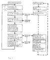
- the new method requires a, preferably microprocessor-controlled, parallel control device which is connected in series to the individual voltage regulators, which, as is known from the prior art, are each associated with each step transformer.
- the serial data lines reduce the likelihood of wiring and other errors.
- a parallel control unit P is informed of the current step transformer configuration, i.e. the information about which step transformers work on which busbars connected in parallel.
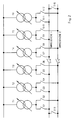
- step transformers T1 ... T6 can be linked to the two busbars in all conceivable switching combinations.
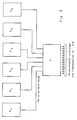
- Each step transformer T1 ... T6 is assigned a voltage regulator R1 ... R6, which measures the amplitudes of voltage and current and the phase angle on each step transformer in a manner known per se and successively transmits these values to a parallel control device P via serial data lines.
- the disturbance variable and the partial load current are in turn transmitted to the individual voltage regulators R1 ... R6 via the serial data lines.
- each voltage regulator R1 ... R6 a disturbance variable is generated in a manner known per se according to the line drop compensation (LDC) method for compensating for the voltage drop (cf. DE-A-2 504 278).
- LDC line drop compensation
- the line voltage drop can thus be compensated for in a manner known per se.
- the serial data line can also be designed as a ring line (e.g. RS485) instead of as a point-to-point connection as described.
Landscapes
- Engineering & Computer Science (AREA)
- Power Engineering (AREA)
- Physics & Mathematics (AREA)
- Electromagnetism (AREA)
- General Physics & Mathematics (AREA)
- Radar, Positioning & Navigation (AREA)
- Automation & Control Theory (AREA)
- Supply And Distribution Of Alternating Current (AREA)
- Control Of Electrical Variables (AREA)
- Inverter Devices (AREA)
Claims (2)
- Procédé pour la régulation du fonctionnement en parallèle de transformateurs à prises (T1...T6) équipés de commutateurs d'échelons pour commuter sous charge différents échelons de tension et fonctionnant en parallèle dans un système de barres omnibus, procédé dans lequel la position respective des sectionneurs et des commutateurs de puissance du système est détectée par des contacts de signalisation (S1...S16) et dans lequel, en outre, à chaque transformateur à prises (T1...T6) est associé un régulateur de tension distinct (R1...R6) qui agit sur l'entraînement respectif du moteur, lequel actionne à son tour le commutateur d'échelon correspondant,
procédé caractérisé en ce que dans un appareil de commande en parallèle (P), il est détecté par la position des contacts de signalisation (Si...S16) quels transformateurs à prises (T)...T6) fonctionnent en parallèle et en quelle configuration,
et ce qu'ensuite, dans les régulateurs de tension (R1...R6), les valeurs actuelles de l'amplitude et de l'angle de phase de la tension et du courant du transformateur à prises respectif (T1...T6) sont mesurées et sont transmises par les lignes de données en série à l'appareil de commande en parallèle (P),
en ce qu'ensuite, à partir de ces valeurs individuelles pour chaque transformateur à prises (T1...T6) le courant de charge partielle et le courant réactif du circuit sont déterminés et ensuite une première grandeur perturbatrice est générée en tant que grandeur d'influence pour les différents régulateurs de tension (R1...R6),
en ce que les valeurs de courant de charge partiel et de la première grandeur perturbatrice sont respectivement transmises par l'intermédiaire des lignes de données en série, à partir de l'appareil de commande en parallèle (P) vers les régulateurs de tension correspondants (R1...R6),
en ce qu'ensuite, à partir du courant respectif de charge partiel dans le régulateur de tension correspondant (R1...R6), une seconde grandeur perturbatrice est produite pour la compensation de la chute de tension de ligne,
en ce qu'enfin, les valeurs de la tension mesurée, de la première grandeur perturbatrice et de la seconde grandeur perturbatrice sont totalisées dans chaque régulateur de tension (R1...R6) et branchées sur la grandeur de réglage. - Procédé selon la revendication 1, caractérisé en ce que la ligne de données en série revêt la forme d'une ligne annulaire.
Applications Claiming Priority (2)
| Application Number | Priority Date | Filing Date | Title |
|---|---|---|---|
| DE4033391A DE4033391C2 (de) | 1990-10-20 | 1990-10-20 | Verfahren zur Parallellaufregelung von Stufentransformatoren |
| DE4033391 | 1990-10-20 |
Publications (3)
| Publication Number | Publication Date |
|---|---|
| EP0482361A2 EP0482361A2 (fr) | 1992-04-29 |
| EP0482361A3 EP0482361A3 (en) | 1992-12-09 |
| EP0482361B1 true EP0482361B1 (fr) | 1995-08-09 |
Family
ID=6416709
Family Applications (1)
| Application Number | Title | Priority Date | Filing Date |
|---|---|---|---|
| EP91116091A Expired - Lifetime EP0482361B1 (fr) | 1990-10-20 | 1991-09-21 | Procédure pour la régulation parallèle des transformateurs aux gradins |
Country Status (4)
| Country | Link |
|---|---|
| US (1) | US5210443A (fr) |
| EP (1) | EP0482361B1 (fr) |
| AT (1) | ATE126370T1 (fr) |
| DE (2) | DE4033391C2 (fr) |
Families Citing this family (17)
| Publication number | Priority date | Publication date | Assignee | Title |
|---|---|---|---|---|
| EP0598130B1 (fr) * | 1991-08-23 | 2001-02-21 | Mitsubishi Denki Kabushiki Kaisha | Appareil de distribution |
| DE4424886C1 (de) * | 1994-07-14 | 1995-11-16 | Reinhausen Maschf Scheubeck | Verfahren zur Darstellung der Anlagenkonfiguration von beliebig auf mehreren Sammelschienen parallelgeschalteten Stufentransformatoren mit Spannungsregler und Monitorfeld zur Darstellung |
| US5530338A (en) * | 1995-03-06 | 1996-06-25 | Beckwith; Robert W. | Load tapchanger transformer paralleling by daisy chain comparison of load currents |
| US6788035B2 (en) * | 2001-06-12 | 2004-09-07 | Primarion, Inc. | Serial bus control method and apparatus for a microelectronic power regulation system |
| US7271572B2 (en) | 2005-10-24 | 2007-09-18 | Schweitzer Engineering Laboratories, Inc. | Apparatus and methods for providing a voltage adjustment for single-phase voltage regulator operation in a three-phase power system |
| US7504806B2 (en) * | 2005-10-21 | 2009-03-17 | Schweitzer Engineering Laboratories, Inc. | Apparatus and methods for controlling operation of a single-phase voltage regulator in a three-phase power system |
| DE102008053193A1 (de) * | 2008-10-24 | 2010-04-29 | Maschinenfabrik Reinhausen Gmbh | Verfahren zur Parallelsteuerung von Transformatoren mit Stufenschaltern |
| US7888815B2 (en) * | 2008-12-31 | 2011-02-15 | Lsi Corporation | AC/DC power supply, a method of delivering DC power at multiple voltages and a computer data storage system employing the power supply or the method |
| US9256232B2 (en) | 2009-06-12 | 2016-02-09 | Schweitzer Engineering Laboratories, Inc. | Voltage regulation using multiple voltage regulator controllers |
| US8427131B2 (en) * | 2009-06-12 | 2013-04-23 | Schweitzer Engineering Laboratories Inc | Voltage regulation at a remote location using measurements from a remote metering device |
| US8476874B2 (en) | 2009-10-13 | 2013-07-02 | Schweitzer Engineering Laboratories, Inc | Systems and methods for synchronized control of electrical power system voltage profiles |
| BRPI1106471B1 (pt) | 2011-10-17 | 2020-12-22 | Companhia Hidro Elétrica Do São Francisco - Chesf | método de regulação de tensão e paralelismo entre diferentes modelos de fontes de tensão e/ou vãos energizados de alta tensão |
| US8847570B1 (en) * | 2013-04-30 | 2014-09-30 | Utilidata, Inc. | Line drop compensation methods and systems |
| DE102014119158A1 (de) | 2014-12-19 | 2016-06-23 | Maschinenfabrik Reinhausen Gmbh | Selektives Parallellaufverfahren für Mess-/Steuergeräte |
| US11361920B2 (en) * | 2017-01-06 | 2022-06-14 | Eaton Intelligent Power Limited | Control system for an electrical apparatus |
| EP3447602B1 (fr) * | 2017-08-22 | 2024-07-03 | Siemens Aktiengesellschaft | Procédé et dispositif de commande de réglage de la tension d'un système de transformateur |
| CN109921380B (zh) * | 2019-02-02 | 2021-05-07 | 国网浙江省电力有限公司丽水供电公司 | 一种用于防止重动并列装置反充电的保护装置 |
Citations (1)
| Publication number | Priority date | Publication date | Assignee | Title |
|---|---|---|---|---|
| DE2504278B1 (de) * | 1975-02-01 | 1976-04-15 | Gossen Gmbh | Anordnung fuer spannungsregler |
Family Cites Families (9)
| Publication number | Priority date | Publication date | Assignee | Title |
|---|---|---|---|---|
| AT126517B (de) * | 1929-06-11 | 1932-01-25 | Siemens Ag | Einrichtung zur Überwachung des Betriebes einer Gruppe von parallel arbeitenden Stufentransformatoren. |
| DE1156880B (de) * | 1957-11-04 | 1963-11-07 | Licentia Gmbh | Einrichtung zur Einsteuerung einer mittleren Stufengleichheit fuer Regeltransformatoren |
| FR1279465A (fr) * | 1960-11-10 | 1961-12-22 | Acec | Dispositif de protection pour transformateurs fonctionnant en parallèle |
| DE2616798B1 (de) * | 1976-04-15 | 1977-10-06 | Reinhausen Maschf Scheubeck | Spannungsregler fuer stufentransformatoren |
| DE2630933C3 (de) * | 1976-07-09 | 1980-07-31 | Maschinenfabrik Reinhausen Gebrueder Scheubeck Gmbh & Co Kg, 8400 Regensburg | Spannungsregler für Stufentransformatoren |
| US4403292A (en) * | 1979-05-30 | 1983-09-06 | Sundstrand Corporation | Control for an electrical generating and distribution system, and method of operation |
| JPS5913730B2 (ja) * | 1979-09-05 | 1984-03-31 | 富士写真フイルム株式会社 | カラ−画像形成方法 |
| DE3032874C2 (de) * | 1980-09-01 | 1984-05-03 | Volta-Werke Elektricitäts-Gesellschaft mbH, 1000 Berlin | Einrichtung zur Steuerung des selbsttätigen Parallellaufs einer Vielzahl von Transformatoren |
| DE4004671C1 (en) * | 1990-02-15 | 1991-09-19 | Maschinenfabrik Reinhausen Gmbh, 8400 Regensburg, De | Automatically identifying installation configuration - using computer to cover stepped transformers coupled to bus=bars as desired and for regulation |
-
1990
- 1990-10-20 DE DE4033391A patent/DE4033391C2/de not_active Expired - Fee Related
-
1991
- 1991-09-21 EP EP91116091A patent/EP0482361B1/fr not_active Expired - Lifetime
- 1991-09-21 AT AT91116091T patent/ATE126370T1/de not_active IP Right Cessation
- 1991-09-21 DE DE59106210T patent/DE59106210D1/de not_active Expired - Fee Related
- 1991-10-15 US US07/776,571 patent/US5210443A/en not_active Expired - Fee Related
Patent Citations (1)
| Publication number | Priority date | Publication date | Assignee | Title |
|---|---|---|---|---|
| DE2504278B1 (de) * | 1975-02-01 | 1976-04-15 | Gossen Gmbh | Anordnung fuer spannungsregler |
Non-Patent Citations (1)
| Title |
|---|
| Betriebsanweisung 63/82 Maschinenfabrik Reinhausen * |
Also Published As
| Publication number | Publication date |
|---|---|
| DE4033391A1 (de) | 1992-04-23 |
| US5210443A (en) | 1993-05-11 |
| DE59106210D1 (de) | 1995-09-14 |
| ATE126370T1 (de) | 1995-08-15 |
| EP0482361A2 (fr) | 1992-04-29 |
| DE4033391C2 (de) | 1994-06-09 |
| EP0482361A3 (en) | 1992-12-09 |
Similar Documents
| Publication | Publication Date | Title |
|---|---|---|
| EP0482361B1 (fr) | Procédure pour la régulation parallèle des transformateurs aux gradins | |
| EP1168271A2 (fr) | Système de couplage d'un bus de terrain pour actionneurs ou capteurs | |
| EP3164726B1 (fr) | Procédé et dispositif de contrôle d'un commutateur à gradins d'un transformateur | |
| EP3164724B1 (fr) | Procédé et dispositif de contrôle d'un commutateur à gradins d'un transformateur | |
| DE3445360A1 (de) | Energieuebertragungssystem | |
| EP0083306A1 (fr) | Procédé et dispositif pour la régulation d'au moins une bobine de compensation dans un réseau polyphasé | |
| EP4100751B1 (fr) | Amplificateur commutable | |
| EP2389723B1 (fr) | Méthode pour le contrôle parallèle des transformateurs avec des changeurs de prise | |
| EP3164725B1 (fr) | Procédé et dispositif de contrôle d'un commutateur à gradins d'un transformateur | |
| DE19850869B4 (de) | Leitungskopplung und Verwendung einer Leitungskopplung in einem Bussystem | |
| DE20219467U1 (de) | Einrichtung zur Fehlererkennung und Verriegelung von Leistungsschaltern | |
| DE102019112713B4 (de) | Schalteranordnung und verfahren zum sicheren betrieb einer schalteranordnung | |
| EP0692858B1 (fr) | Méthode pour représenter la configuration d'installations de transformateurs à gradins connectés en parallèle sur un nombre quelconque de barres omnibus, avec régulateur de tension et zone de moniteur pour la représentation | |
| DE2721813C3 (de) | Verfahren zum Ermitteln des Isolationswiderstandes elektrischer Netze mit Stromrichtern und Einrichtung zur Durchführung des Verfahrens | |
| DE102019208954A1 (de) | Verfahren zur Bestimmung von Phasenströmen eines Wechselrichters, Vorrichtung und Fahrzeug | |
| EP4226403B1 (fr) | Changeur de prises en charge et procédé pour actionner un changeur de prises en charge | |
| AT412248B (de) | Verfahren zur erkennung von asymmetrien in drehfeldmaschinen während des betriebes durch rekonstruktion des stromraumzeigers | |
| DE102018204413A1 (de) | Regelung von Sättigungseffekten von Transformatoren | |
| DE4301810A1 (de) | Thyristor-Steuereinheit | |
| EP0232809B1 (fr) | Procédé et dispositif pour la mise en parallèle de branchements ou de réseaux comprenant des générateurs synchrones | |
| DE731011C (de) | Rueckmeldevorrichtung fuer Hochspannungs-UEberlagerungsfernsteueranlagen | |
| DE969345C (de) | Verfahren und Einrichtung zur Fehlerabgleichtung von elektrischen Leistungs- und Arbeitsmessern, insbesondere Elektrizitaetszaehlern | |
| EP0446451A2 (fr) | Procédé de commande d'un régulateur de puissance réactive | |
| DE102020216365A1 (de) | Ansteuerschaltung für eine Gruppe von elektrischen Maschinen sowie ein Verfahren zum Betreiben eines Motorsystems mit mehreren Elektromotoren | |
| JPH07169624A (ja) | 変圧器用タップ切換制御装置 |
Legal Events
| Date | Code | Title | Description |
|---|---|---|---|
| PUAI | Public reference made under article 153(3) epc to a published international application that has entered the european phase |
Free format text: ORIGINAL CODE: 0009012 |
|
| AK | Designated contracting states |
Kind code of ref document: A2 Designated state(s): AT BE CH DE FR LI NL |
|
| EL | Fr: translation of claims filed | ||
| PUAL | Search report despatched |
Free format text: ORIGINAL CODE: 0009013 |
|
| AK | Designated contracting states |
Kind code of ref document: A3 Designated state(s): AT BE CH DE FR LI NL |
|
| 17P | Request for examination filed |
Effective date: 19921117 |
|
| 17Q | First examination report despatched |
Effective date: 19940704 |
|
| GRAA | (expected) grant |
Free format text: ORIGINAL CODE: 0009210 |
|
| AK | Designated contracting states |
Kind code of ref document: B1 Designated state(s): AT BE CH DE FR LI NL |
|
| REF | Corresponds to: |
Ref document number: 126370 Country of ref document: AT Date of ref document: 19950815 Kind code of ref document: T |
|
| ET | Fr: translation filed | ||
| REF | Corresponds to: |
Ref document number: 59106210 Country of ref document: DE Date of ref document: 19950914 |
|
| PLBE | No opposition filed within time limit |
Free format text: ORIGINAL CODE: 0009261 |
|
| STAA | Information on the status of an ep patent application or granted ep patent |
Free format text: STATUS: NO OPPOSITION FILED WITHIN TIME LIMIT |
|
| 26N | No opposition filed | ||
| PGFP | Annual fee paid to national office [announced via postgrant information from national office to epo] |
Ref country code: CH Payment date: 20000831 Year of fee payment: 10 |
|
| PGFP | Annual fee paid to national office [announced via postgrant information from national office to epo] |
Ref country code: BE Payment date: 20000907 Year of fee payment: 10 |
|
| PGFP | Annual fee paid to national office [announced via postgrant information from national office to epo] |
Ref country code: AT Payment date: 20000925 Year of fee payment: 10 |
|
| PGFP | Annual fee paid to national office [announced via postgrant information from national office to epo] |
Ref country code: FR Payment date: 20000929 Year of fee payment: 10 |
|
| PGFP | Annual fee paid to national office [announced via postgrant information from national office to epo] |
Ref country code: NL Payment date: 20000930 Year of fee payment: 10 |
|
| PGFP | Annual fee paid to national office [announced via postgrant information from national office to epo] |
Ref country code: DE Payment date: 20001101 Year of fee payment: 10 |
|
| PG25 | Lapsed in a contracting state [announced via postgrant information from national office to epo] |
Ref country code: AT Free format text: LAPSE BECAUSE OF NON-PAYMENT OF DUE FEES Effective date: 20010921 |
|
| PG25 | Lapsed in a contracting state [announced via postgrant information from national office to epo] |
Ref country code: LI Free format text: LAPSE BECAUSE OF NON-PAYMENT OF DUE FEES Effective date: 20010930 Ref country code: CH Free format text: LAPSE BECAUSE OF NON-PAYMENT OF DUE FEES Effective date: 20010930 Ref country code: BE Free format text: LAPSE BECAUSE OF NON-PAYMENT OF DUE FEES Effective date: 20010930 |
|
| BERE | Be: lapsed |
Owner name: MASCHINENFABRIK REINHAUSEN G.M.B.H. Effective date: 20010930 |
|
| PG25 | Lapsed in a contracting state [announced via postgrant information from national office to epo] |
Ref country code: NL Free format text: LAPSE BECAUSE OF NON-PAYMENT OF DUE FEES Effective date: 20020401 |
|
| PG25 | Lapsed in a contracting state [announced via postgrant information from national office to epo] |
Ref country code: DE Free format text: LAPSE BECAUSE OF NON-PAYMENT OF DUE FEES Effective date: 20020501 |
|
| REG | Reference to a national code |
Ref country code: CH Ref legal event code: PL |
|
| PG25 | Lapsed in a contracting state [announced via postgrant information from national office to epo] |
Ref country code: FR Free format text: LAPSE BECAUSE OF NON-PAYMENT OF DUE FEES Effective date: 20020531 |
|
| NLV4 | Nl: lapsed or anulled due to non-payment of the annual fee |
Effective date: 20020401 |
|
| REG | Reference to a national code |
Ref country code: FR Ref legal event code: ST |
|
| NLV4 | Nl: lapsed or anulled due to non-payment of the annual fee |
Effective date: 20020401 |