EP0483364A1 - Diskretes wiederholungssteuerverfahren und vorrichtung dafür - Google Patents
Diskretes wiederholungssteuerverfahren und vorrichtung dafür Download PDFInfo
- Publication number
- EP0483364A1 EP0483364A1 EP91908464A EP91908464A EP0483364A1 EP 0483364 A1 EP0483364 A1 EP 0483364A1 EP 91908464 A EP91908464 A EP 91908464A EP 91908464 A EP91908464 A EP 91908464A EP 0483364 A1 EP0483364 A1 EP 0483364A1
- Authority
- EP
- European Patent Office
- Prior art keywords
- time delay
- elements
- gain
- controlled object
- deviation
- Prior art date
- Legal status (The legal status is an assumption and is not a legal conclusion. Google has not performed a legal analysis and makes no representation as to the accuracy of the status listed.)
- Granted
Links
- 238000000034 method Methods 0.000 title claims description 13
- 238000005070 sampling Methods 0.000 claims abstract description 29
- 230000003252 repetitive effect Effects 0.000 claims description 42
- 125000004122 cyclic group Chemical group 0.000 claims description 36
- 238000010586 diagram Methods 0.000 description 4
- 238000003754 machining Methods 0.000 description 1
- 239000011159 matrix material Substances 0.000 description 1
Images

Classifications
-
- G—PHYSICS
- G05—CONTROLLING; REGULATING
- G05B—CONTROL OR REGULATING SYSTEMS IN GENERAL; FUNCTIONAL ELEMENTS OF SUCH SYSTEMS; MONITORING OR TESTING ARRANGEMENTS FOR SUCH SYSTEMS OR ELEMENTS
- G05B21/00—Systems involving sampling of the variable controlled
- G05B21/02—Systems involving sampling of the variable controlled electric
Definitions
- the present invention relates to repetitive control for causing a controlled object to conduct a repetitive action in response to a cyclic target input, and more particularly, to a discrete-type repetitive control method and an apparatus therefor, having an excellent response to a cyclic target input and excellent flexibility to a variation in the cycle period of a target input.
- a cyclic target input generation model represented by 1/(Z L -1) is employed, in view of equation (3) obtained by substituting equation (2) into a Z transform Yr(Z) of a cyclic target input y(t) represented by equation (1).
- Yr0(Z) r0 + r1Z ⁇ 1 + --- + r L-1 Z L-1
- Yr(Z) Z L ⁇ Yr0(Z)/(Z L - 1) (3)
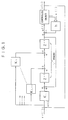
- the conventional discrete-type repetitive control system accommodates therein an internal model 1/(Z L - 1) which is comprised of L' time delay elements Z ⁇ 1.
- the number L' of the time delay elements Z ⁇ 1 is equal to a value obtained by dividing the cycle period L of the cyclic target input by a sampling cycle period ⁇ of the cyclic target input in the control system.
- symbol yr(i) represents the cyclic target input; u(i), an input to the controlled object; and y(i), an output of the controlled object.
- Symbol x(i) indicates a state variable of the controlled object; and e(i), a deviation between the output y(i) of the controlled object and the cyclic target input yr(i).
- symbol h represents a feedback gain element having a properly selected gain
- K1 - KL indicate gain compensators having properly selected gains.
- the repetitive control system According to the repetitive control system, a stable control system is provided. However, if the state variable x (i) cannot be observed directly, then the repetitive control system shown in Fig. 1 cannot be configured. Further, according to the control system, the number L' of the time delay elements Z ⁇ 1 must be equal to the value obtained by dividing the cycle L of the target input by the sampling cycle ⁇ . Therefore, the conventional repetitive control system lacks flexibility to a variation in the cycle period of a target input.
- An object of the present invention is to provide a discrete-type repetitive control method and an apparatus therefor, which enable stable repetitive control even if a state variable of a controlled object is not observable, and which have an excellent response to a cyclic target input and excellent flexibility to a variation in the cycle period of a target input.
- a discrete-type repetitive control method comprises the steps of: (a) periodically applying, to each of time delay elements which are equal to or greater in number than a value obtained by dividing a cycle period of a cyclic target input by a cycle period of sampling a deviation between an output of a controlled object and the cyclic target input, a sum of a product of the deviation periodically sampled and a first gain associated with the time delay element, a product of an input to the controlled object and a second gain associated with the time delay element, and an output of a preceding time delay element; and (b) periodically applying, to the controlled object, a sum of a product of the periodically sampled deviation and a third gain, and an output of a time delay element disposed on a side of the controlled object.
- a discrete-type repetitive control unit comprises: (a) time delay elements which are equal to or greater in number than a value obtained by dividing a cycle period of a cyclic target input by a cycle period of sampling a deviation between an output of a controlled object and the cyclic target input, the time delay elements being connected in series with each other; (b) first gain elements each disposed on an input side of a corresponding one of the time delay elements; (c) first adder elements each interposed between a corresponding one of the time delay elements and a corresponding one of the first gain elements; (d) second gain elements each interposed between an input side of the controlled object and a corresponding one of the first adder elements; (e) a second adder element interposed between the input side of the controlled object and a last time delay element connected thereto; and (f) a third gain element disposed on an input side of the second adder element.
- time delay elements which are equal to or greater in number than the value obtained by dividing the cycle period of the cyclic target input by the sampling period of the deviation between the controlled object output and the cyclic target input.
- Each time delay element is periodically applied with the sum of the product of a periodically sampled deviation and the first gain associated with each time delay element, the product of an input to the controlled object and the second gain associated with each time delay element, and an output of the preceding time delay element. Further, the sum of the product of the periodically sampled deviation and the third gain, and an output of the time delay element disposed on the controlled object side is periodically applied to the controlled object.
- the repetitive control system is excellent in flexibility to a variation in the cycle period of the cyclic target input.
- a process of deriving a feedback control rule for embodying a repetitive control method will be explained.
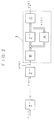
- a feedback control rule in the extended system shown in Fig. 2 and consisting of a controlled object and n time delay elements Z ⁇ 1 connected thereto will be determined.
- a cyclic target input u(i ⁇ ) is applied at intervals of a cycle period T to the input side of the extended system, and the target input u(i ⁇ ) is sampled at intervals of a sampling period ⁇ .
- the cyclic target input u(i ⁇ ) changes in a single changing pattern (not shown), and the changing pattern is repeated at intervals of a cycle period T.
- the total number n of the time delay elements Z ⁇ 1 is equal to or greater than a value obtained by dividing the period T of the target input u(i ⁇ ) by the sampling period ⁇ .
- the element number is equal to an integer obtained by counting fractions of decimals of the resultant value of division as a whole number.
- each of the n time delay elements Z ⁇ 1 is connected to the input side of the next time delay element Z ⁇ 1, and the output side of the n-th time delay element Z ⁇ 1 is connected to the input side of a controlled object 1.
- the controlled object 1 which is a robot, machining tool or the like, includes gain elements A. B, and C whose gains are A, B, and C, respectively, and a time delay element Z ⁇ 1.
- the output of the time delay element Z ⁇ 1, indicative of a state variable x of the controlled object 1, is applied to the input side of the time delay element Z ⁇ 1 through the gain element A.
- the state variable x(k+1) of the controlled object 1 at a given sampling point k+n+1 is represented by equation (4), i.e., by the state variable x(k) at the preceding sampling point k+n, the input u(k) to the controlled object 1, and the gains A and B. Further, an output y(k) of the controlled object 1 is represented by equation 15), i.e., by the state variable x(k) and the gain C.
- x(k+1) Ax(k) + Bu(k) (4)
- y(k) Cx(k) (5)
- equation (6) indicative of the feedback control rule in the extended system shown in Fig. 2.
- symbols A, B, and x indicate matrixes.
- the feedback control rule represented by the equation (9) does not include the state variable x of the controlled object 1.
- the feedback control rule can be executed by the control unit shown in Fig. 3.
- symbol u(k+n) indicates a cyclic target input sampled at a sampling point k+n.
- Symbol u(k) indicates an input to the controlled object 1 (Fig. 2) at a sampling point k+n
- symbol -y(k) indicates an output of the controlled object 1.
- equation (10 - 1) is shown again.
- the feedback control rule for embodying the discrete-type repetitive control method of this embodiment is represented by the foregoing equations (10-1), (12), (13), and (14-2) to (14-n).
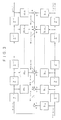
- a series compensator corresponding to this feedback control rule is shown in Fig. 4.
- the deviation yr(k) - y(k) between the cyclic target input yr(k) (Fig. 1) and the output y(k) of the controlled object (Fig. 2) is applied, in place of the input -y(k) shown in Fig. 4, to the series compensator.
- the discrete-type repetitive control unit for embodying the repetitive control method of the embodiment comprises the series compensator of Fig. 4.
- the control unit also includes a sampling circuit (e.g., a sample-and-hold circuit), represented by the junction (Fig. 4) of a -y(k) signal input line and a gain element hj, for periodically sampling the deviation between the output of the controlled object and the cyclic target input. If the sampling circuit is provided outside the control unit, or if a quantized deviation is periodically applied to the control unit, then it is unnecessary to provide the sampling circuit inside the control unit.
- the repetitive control unit may be configured by a digital unit, e.g., a digital controller, for achieving the functions of the series compensator of Fig. 4.
- the repetitive control unit comprises time delay elements Z ⁇ 1 connected in series with each other. These time delay elements are provided by that number which is equal to or greater than a value obtained by dividing the cycle period of the cyclic target input by the deviation sampling period. Preferably, the elements are equal in number to an integer obtained by counting fractions of decimals of a resultant value of division as a whole number.
- Each of first gain elements h1 - hn is interposed between the sampling circuit and a corresponding one of the time delay elements Z ⁇ 1. Generally, each gain element is disposed on the input side of the time delay element Z ⁇ 1.
- a corresponding one of first adder elements is interposed between each of the time delay elements and an associated one of the first gain elements h1, ---, or hn, and a corresponding one of second gain elements m1 - mn is interposed between the input side of the controlled object and each of the first adder elements.
- a second adder element is interposed between the input side of the controlled object and the last time delay element Z ⁇ 1 connected thereto, and a third gain element h0 is provided between the sampling circuit and the second adder element (generally, on the input side of the second adder element).
- at least one of the first gains h1 - hn and the second gains m1 - mn may be zero.
- the sum (series compensator output) u(k) of the product of the deviation and the third gain h0, and the output W1(k) of the time delay element disposed on the controlled object side is periodically applied to the controlled object 1 (Fig. 2).
- the controlled object 1 operates in a stable manner, with no substantial delay to the cyclic target input, in accordance with the repetitive control output u(k) responsive to the cyclic target input yr(k) which changes periodically in a single changing pattern, so that the controlled object repeats a single patterned action.
- repetitive control unit which corresponds to the series compensator of Fig. 4
- repetitive control with a minimized delay to the cyclic target input can be achieved.
- the repetitive control unit can be configured even if the state variable x of the controlled object 1 is not observable directly.
- the number of the time delay elements Z ⁇ 1 to be included in the repetitive control unit is not necessarily equal to the value obtained by dividing the cycle period of the cyclic target input by the deviation sampling period, as long as it is equal to or greater than such a value.
- the repetitive control unit provides excellent flexibility to a variation in the cycle period of the cyclic target input.
Landscapes
- Physics & Mathematics (AREA)
- General Physics & Mathematics (AREA)
- Engineering & Computer Science (AREA)
- Automation & Control Theory (AREA)
- Feedback Control In General (AREA)
Applications Claiming Priority (3)
| Application Number | Priority Date | Filing Date | Title |
|---|---|---|---|
| JP103058/90 | 1990-04-20 | ||
| JP2103058A JPH043208A (ja) | 1990-04-20 | 1990-04-20 | ディジタル型繰り返し制御方式 |
| PCT/JP1991/000528 WO1991016674A1 (fr) | 1990-04-20 | 1991-04-20 | Procede et appareil de commande de repetition de type discret |
Publications (3)
| Publication Number | Publication Date |
|---|---|
| EP0483364A1 true EP0483364A1 (de) | 1992-05-06 |
| EP0483364A4 EP0483364A4 (en) | 1993-08-04 |
| EP0483364B1 EP0483364B1 (de) | 1995-11-02 |
Family
ID=14344078
Family Applications (1)
| Application Number | Title | Priority Date | Filing Date |
|---|---|---|---|
| EP91908464A Expired - Lifetime EP0483364B1 (de) | 1990-04-20 | 1991-04-20 | Diskretes wiederholungssteuerverfahren und vorrichtung dafür |
Country Status (5)
| Country | Link |
|---|---|
| US (1) | US5220265A (de) |
| EP (1) | EP0483364B1 (de) |
| JP (1) | JPH043208A (de) |
| DE (1) | DE69114246T2 (de) |
| WO (1) | WO1991016674A1 (de) |
Cited By (1)
| Publication number | Priority date | Publication date | Assignee | Title |
|---|---|---|---|---|
| US5708341A (en) * | 1994-10-07 | 1998-01-13 | Omron Corporation | Control apparatus and method with correction of trial manipulated pattern |
Families Citing this family (7)
| Publication number | Priority date | Publication date | Assignee | Title |
|---|---|---|---|---|
| JPH05216503A (ja) * | 1992-01-23 | 1993-08-27 | Nec Corp | ディジタル制御方式 |
| EP0587897B1 (de) * | 1992-03-31 | 1999-07-14 | Kabushiki Kaisha Yaskawa Denki | Gerät zur prädiktiven regelung |
| US5563794A (en) * | 1993-11-22 | 1996-10-08 | Hughes Aircraft Company | Repetitive control of thermal shock disturbance |
| US5481453A (en) * | 1994-08-25 | 1996-01-02 | Corporation De L'ecole Polytechnique | Dual loop PID configuration |
| JP4483314B2 (ja) * | 2004-01-28 | 2010-06-16 | 株式会社安川電機 | サーボ制御装置 |
| US20100049943A1 (en) * | 2008-08-25 | 2010-02-25 | Central Digital Inc. | Programmable control pipeline architecture and pipeline processing system thereof |
| EP2573631B1 (de) * | 2011-09-23 | 2015-10-21 | Honeywell spol s.r.o. | Steuergerät zur Abschätzung von verzögerten manipulierten Variablen |
Family Cites Families (11)
| Publication number | Priority date | Publication date | Assignee | Title |
|---|---|---|---|---|
| GB1500132A (en) * | 1974-03-07 | 1978-02-08 | Standard Telephones Cables Ltd | Multi-level data scramblers and descramblers |
| JPS514475A (ja) * | 1974-06-28 | 1976-01-14 | Chiyoda Chem Eng Construct Co | Sanpuruchiseigyohoshiki |
| JPH0677201B2 (ja) * | 1986-04-04 | 1994-09-28 | 三菱重工業株式会社 | 繰返し制御器 |
| JPH0792685B2 (ja) * | 1987-04-06 | 1995-10-09 | 三菱重工業株式会社 | 繰返し制御装置 |
| JPH0830979B2 (ja) * | 1988-03-17 | 1996-03-27 | 株式会社安川電機 | 周期的目標値に最適に追従する制御方法 |
| US5119287A (en) * | 1987-09-11 | 1992-06-02 | Kabushiki Kaisha Yaskawa Denki Seisakusho | Optimum tracking control method for periodic target value |
| JPH0196701A (ja) * | 1987-10-09 | 1989-04-14 | Nobuo Yamamoto | 内部モデル協調型フイードフオワード手法を用いた制御系 |
| US5065263A (en) * | 1988-05-20 | 1991-11-12 | Matsushita Electric Industrial Co., Ltd. | Track following transducer position control system for a disk storage drive system |
| JPH01318103A (ja) * | 1988-06-20 | 1989-12-22 | Michio Nakano | 繰返し制御装置 |
| US4918584A (en) * | 1988-07-08 | 1990-04-17 | Performance Controls, Inc. | Self-adjusting servo device and method |
| US5050119A (en) * | 1989-10-06 | 1991-09-17 | North American Philips Corporation | Optimized sparse transversal filter |
-
1990
- 1990-04-20 JP JP2103058A patent/JPH043208A/ja active Pending
-
1991
- 1991-04-20 WO PCT/JP1991/000528 patent/WO1991016674A1/ja not_active Ceased
- 1991-04-20 US US07/778,806 patent/US5220265A/en not_active Expired - Fee Related
- 1991-04-20 DE DE69114246T patent/DE69114246T2/de not_active Expired - Fee Related
- 1991-04-20 EP EP91908464A patent/EP0483364B1/de not_active Expired - Lifetime
Cited By (1)
| Publication number | Priority date | Publication date | Assignee | Title |
|---|---|---|---|---|
| US5708341A (en) * | 1994-10-07 | 1998-01-13 | Omron Corporation | Control apparatus and method with correction of trial manipulated pattern |
Also Published As
| Publication number | Publication date |
|---|---|
| WO1991016674A1 (fr) | 1991-10-31 |
| EP0483364A4 (en) | 1993-08-04 |
| US5220265A (en) | 1993-06-15 |
| JPH043208A (ja) | 1992-01-08 |
| DE69114246D1 (de) | 1995-12-07 |
| EP0483364B1 (de) | 1995-11-02 |
| DE69114246T2 (de) | 1996-03-21 |
Similar Documents
| Publication | Publication Date | Title |
|---|---|---|
| EP0104845B1 (de) | Vorrichtung zum Steuern von Prozessen | |
| US4634946A (en) | Apparatus and method for predictive control of a dynamic system | |
| EP0483364A1 (de) | Diskretes wiederholungssteuerverfahren und vorrichtung dafür | |
| JPH0534682B2 (de) | ||
| US3705978A (en) | Time shared digital and analog process control | |
| Oaks et al. | Piecewise linear control of nonlinear systems | |
| EP0510649A2 (de) | Steuerung mit Rückkoppelung | |
| US3743823A (en) | Feedback control system with digital control elements | |
| Gaikwad et al. | Multivariable frequency-response curve fitting with application to control-relevant parameter estimation | |
| O’Brien Jr et al. | Robust controller design for linear, time-varying systems | |
| JPH03175502A (ja) | 間引き学習制御方式 | |
| Giese et al. | State variable difference methods for digital simulation | |
| Astrom | Robust and adaptive pole placement | |
| Owens et al. | Adaptive iterative learning control | |
| RU2130635C1 (ru) | Адаптивная система управления с переменной структурой | |
| Zhu et al. | Alternative algorithms for generalized predictive control | |
| SU765821A1 (ru) | Интерпол тор | |
| Kurzweil Jr | Dynamic synthesis of higher-order, optimum saturating systems | |
| JP3256950B2 (ja) | 最適予見学習制御装置 | |
| SU851425A1 (ru) | Нелинейный интерпол тор | |
| SU1305631A1 (ru) | Бинарна система управлени нелинейными объектами | |
| SU1439628A1 (ru) | Множительное устройство | |
| SU807212A1 (ru) | Циклова система программногоупРАВлЕНи пРОМышлЕННыМ РОбОТОМ | |
| SU962849A1 (ru) | Система автоматического управлени инерционным объектом | |
| SU842717A1 (ru) | Устройство дл программного управле-Ни Об'ЕКТОМ |
Legal Events
| Date | Code | Title | Description |
|---|---|---|---|
| PUAI | Public reference made under article 153(3) epc to a published international application that has entered the european phase |
Free format text: ORIGINAL CODE: 0009012 |
|
| 17P | Request for examination filed |
Effective date: 19920120 |
|
| AK | Designated contracting states |
Kind code of ref document: A1 Designated state(s): DE IT |
|
| A4 | Supplementary search report drawn up and despatched |
Effective date: 19930614 |
|
| AK | Designated contracting states |
Kind code of ref document: A4 Designated state(s): DE IT |
|
| 17Q | First examination report despatched |
Effective date: 19950320 |
|
| GRAA | (expected) grant |
Free format text: ORIGINAL CODE: 0009210 |
|
| AK | Designated contracting states |
Kind code of ref document: B1 Designated state(s): DE IT |
|
| REF | Corresponds to: |
Ref document number: 69114246 Country of ref document: DE Date of ref document: 19951207 |
|
| ITF | It: translation for a ep patent filed | ||
| PGFP | Annual fee paid to national office [announced via postgrant information from national office to epo] |
Ref country code: DE Payment date: 19960429 Year of fee payment: 6 |
|
| PLBE | No opposition filed within time limit |
Free format text: ORIGINAL CODE: 0009261 |
|
| STAA | Information on the status of an ep patent application or granted ep patent |
Free format text: STATUS: NO OPPOSITION FILED WITHIN TIME LIMIT |
|
| 26N | No opposition filed | ||
| PG25 | Lapsed in a contracting state [announced via postgrant information from national office to epo] |
Ref country code: DE Free format text: LAPSE BECAUSE OF NON-PAYMENT OF DUE FEES Effective date: 19980101 |
|
| PG25 | Lapsed in a contracting state [announced via postgrant information from national office to epo] |
Ref country code: IT Free format text: LAPSE BECAUSE OF NON-PAYMENT OF DUE FEES Effective date: 20050420 |