EP0483554A1 - Procédé pour la réduction au minimum des émissions de NOx dans une combustion - Google Patents
Procédé pour la réduction au minimum des émissions de NOx dans une combustion Download PDFInfo
- Publication number
- EP0483554A1 EP0483554A1 EP91117113A EP91117113A EP0483554A1 EP 0483554 A1 EP0483554 A1 EP 0483554A1 EP 91117113 A EP91117113 A EP 91117113A EP 91117113 A EP91117113 A EP 91117113A EP 0483554 A1 EP0483554 A1 EP 0483554A1
- Authority
- EP
- European Patent Office
- Prior art keywords
- burner
- fuel
- water
- nozzle
- combustion
- Prior art date
- Legal status (The legal status is an assumption and is not a legal conclusion. Google has not performed a legal analysis and makes no representation as to the accuracy of the status listed.)
- Granted
Links
Images
Classifications
-
- F—MECHANICAL ENGINEERING; LIGHTING; HEATING; WEAPONS; BLASTING
- F23—COMBUSTION APPARATUS; COMBUSTION PROCESSES
- F23D—BURNERS
- F23D11/00—Burners using a direct spraying action of liquid droplets or vaporised liquid into the combustion space
- F23D11/36—Details
- F23D11/40—Mixing tubes; Burner heads
- F23D11/402—Mixing chambers downstream of the nozzle
-
- F—MECHANICAL ENGINEERING; LIGHTING; HEATING; WEAPONS; BLASTING
- F23—COMBUSTION APPARATUS; COMBUSTION PROCESSES
- F23D—BURNERS
- F23D17/00—Burners for combustion simultaneously or alternately of gaseous or liquid or pulverulent fuel
- F23D17/002—Burners for combustion simultaneously or alternately of gaseous or liquid or pulverulent fuel gaseous or liquid fuel
-
- F—MECHANICAL ENGINEERING; LIGHTING; HEATING; WEAPONS; BLASTING
- F23—COMBUSTION APPARATUS; COMBUSTION PROCESSES
- F23L—SUPPLYING AIR OR NON-COMBUSTIBLE LIQUIDS OR GASES TO COMBUSTION APPARATUS IN GENERAL ; VALVES OR DAMPERS SPECIALLY ADAPTED FOR CONTROLLING AIR SUPPLY OR DRAUGHT IN COMBUSTION APPARATUS; INDUCING DRAUGHT IN COMBUSTION APPARATUS; TOPS FOR CHIMNEYS OR VENTILATING SHAFTS; TERMINALS FOR FLUES
- F23L7/00—Supplying non-combustible liquids or gases, other than air, to the fire, e.g. oxygen, steam
- F23L7/002—Supplying water
-
- F—MECHANICAL ENGINEERING; LIGHTING; HEATING; WEAPONS; BLASTING
- F23—COMBUSTION APPARATUS; COMBUSTION PROCESSES
- F23C—METHODS OR APPARATUS FOR COMBUSTION USING FLUID FUEL OR SOLID FUEL SUSPENDED IN A CARRIER GAS OR AIR
- F23C2203/00—Flame cooling methods otherwise than by staging or recirculation
- F23C2203/30—Injection of tempering fluids
-
- F—MECHANICAL ENGINEERING; LIGHTING; HEATING; WEAPONS; BLASTING
- F23—COMBUSTION APPARATUS; COMBUSTION PROCESSES
- F23C—METHODS OR APPARATUS FOR COMBUSTION USING FLUID FUEL OR SOLID FUEL SUSPENDED IN A CARRIER GAS OR AIR
- F23C2900/00—Special features of, or arrangements for combustion apparatus using fluid fuels or solid fuels suspended in air; Combustion processes therefor
- F23C2900/07002—Premix burners with air inlet slots obtained between offset curved wall surfaces, e.g. double cone burners
Definitions
- the present invention relates to a method for minimizing NOx emissions according to the preamble of claim 1. It also relates to a burner for carrying out the method according to claim 1.
- the invention seeks to remedy this.
- the invention is based on the object, in a method of the type mentioned, to supply the water to the combustion in such a way that a minimization of the NOx emissions is achieved, but without negative effects on the combustion in the To cause an increase in CO emissions and other pollutants.
- a further advantage of the invention is that when these full jets are used, in narrow burners or combustion chambers, it is avoided that the water can splash onto the walls, because then the desired reduction in NOx formation would not occur from the combustion process.
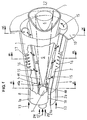
- the burner A according to FIG. 1 consists of two half hollow partial cone bodies 1, 2 which are radially offset with respect to one another with respect to their longitudinal axis of symmetry and stand on one another.
- the two partial cone bodies 1, 2 each have a cylindrical initial part 1a, 2a, which, analogous to the partial cone bodies 1, 2, are offset from one another, so that the tangential air inlet slots 19, 20 are present continuously over the entire length of the burner A.
- a nozzle 3 is accommodated in this cylindrical initial part 1a, 2a, the injection 4 of a preferably liquid fuel 12 coinciding with the narrowest cross-section of the conical cavity 14 formed by the two partial cone bodies 1, 2.
- a gaseous fuel or a mixture of different fuels in different physical states can also be burned.
- This fuel injection 4 is preferably placed in the center of the nozzle.
- the nozzle 3 also has a number of further injections 18, via which water 24 is injected into the conical cavity 14.
- the number of these water jets 18 and their circumferential placement on the end face of the nozzle 3 essentially depends on the size of the burner A and on its combustion characteristics.
- the water jets 18 are preferably to be provided in such a way that they form a ring with respect to the fuel injection 4. wherein the distance to the center of the nozzle 3 is discussed in more detail below.
- the burner A can be provided in a purely conical manner, that is to say without cylindrical starting parts 1a, 2a.
- Both partial cone bodies 1, 2 each have a fuel line 8, 9 provided with openings 17, through which a gaseous fuel 13 is fed, which in turn admixes the combustion air 15 flowing into the conical cavity 14 through the tangential air inlet slots 19, 20 becomes.
- the fuel lines 8, 9 are preferably to be provided at the end of the tangential inflow, immediately before entering the conical cavity 14, in order to achieve an optimal speed-related admixture 16 between the fuel 13 and the inflowing combustion air 15.
- an optimal speed-related admixture 16 between the fuel 13 and the inflowing combustion air 15.
- the outlet opening of the burner A merges into a front wall 10, in which bores (not shown in the figure) can be provided, in order to be able to introduce dilution air or cooling air into the front part of the combustion chamber 22 if necessary.
- the tapered liquid combustion profile 5 is enclosed by the combustion air 15 flowing in tangentially and a further combustion air flow 15a brought axially around the nozzle 3.
- the concentration of the liquid fuel 12 is continuously reduced by the combustion air streams 15, 15a introduced.
- gaseous fuel 13 is used via the fuel lines 8, 9, the mixture formation with the combustion air 15 takes place, as has already been briefly explained above, directly in the area of the air inlet slots 19, 20, at the entry into the conical hollow body 14
- the optimal homogeneous fuel concentration over the cross section is achieved in the area of the vortex burst, ie in the area of the backflow zone 6.
- the ignition takes place at the top of the backflow zone 6.
- a flashback of the flame into the interior of burner A as can always occur latently in known premixing sections, while remedial measures are sought there with complicated flame holders is not to be feared here.
- the combustion air 15 is preheated.
- the backflow zone 6 with the flame front 7 is penetrated with a number of compact full water jets 11, which without this sensitive stabilization zone disturb, namely where the freshly supplied fuel / air mixture is constantly re-ignited, develop.
- These water jets 11 then burst in the interior of the flame, in such a way that the water is distributed, but in a very small area, exactly where there is a potential risk of NOx emissions being formed. This prevents the entire flame body from being acted on, which would lead to instabilities, flame pulsations and poor burn-out, which would result in a surge in CO emissions.
- the alignment of these water jets 11 from the nozzle 3 is to be provided in such a way that firstly penetration of the flame front 7 is ensured and secondly has a selective effect on those zones where there is a potential for NOx emissions to occur.
- narrow limits must be observed so that the desired flow field of the combustion air with its return flow zone 6 is established in the area of the burner mouth, and provides flame stabilization there.
- a reduction in the size of the combustion air inlet slots 19, 20 shifts the backflow zone 6 further downstream, which would cause the mixture to ignite earlier, however.
- the backflow zone 6, once fixed, is inherently position-stable, because the swirl number increases in the direction of flow in the region of the cone shape of the burner A.
- the axial speed can also be influenced by axially supplying the combustion air flow 15a already mentioned.
- the design of the burner A is particularly suitable, given the given overall length of the burner A, of changing the size of the tangential combustion air inlet slots 19, 20 by pushing the partial cone bodies 1, 2 towards or away from one another, as a result of which the distance between the two central axes 1b 2b reduced or enlarges accordingly
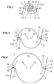
- the gap size of the tangential combustion air inlet slots 19, 20 changed, as can be seen particularly well from FIGS. 4-6.
- the partial cone bodies 1, 2 can also be displaced relative to one another in another plane, as a result of which even an overlap thereof can be controlled. Yes, it is even possible to move the partial cone bodies 1, 2 spirally into one another by a counter-rotating movement, or to move the partial cone bodies 1, 2 against one another by means of an axial movement. It is therefore in your hand to vary the shape and size of the tangential combustion air inlet slots 19, 20 as desired, with which burner A covers a certain operating range without changing its overall length.
- FIGS. 2-4 show the geometric configuration of the guide plates 21a, 21b. They have a flow introduction function, these guide plates, depending on their length, extending the respective end of the partial cone bodies 1, 2 in the direction of flow of the combustion air 15.
- the channeling of the combustion air 15 into the conical cavity 14 can be optimized by opening or closing the guide plates 21a, 21b about a pivot point 23 placed in the area of the entrance to the cavity 14; This is particularly necessary if the original gap size of the tangential combustion air inlet slots 19, 20 is changed.
- burner A can also be operated without baffles 21a, 21b, or other aids can be provided for this.
Landscapes
- Engineering & Computer Science (AREA)
- Chemical & Material Sciences (AREA)
- Combustion & Propulsion (AREA)
- Mechanical Engineering (AREA)
- General Engineering & Computer Science (AREA)
- Pre-Mixing And Non-Premixing Gas Burner (AREA)
Applications Claiming Priority (2)
| Application Number | Priority Date | Filing Date | Title |
|---|---|---|---|
| CH3487/90 | 1990-11-02 | ||
| CH3487/90A CH682009A5 (fr) | 1990-11-02 | 1990-11-02 |
Publications (2)
| Publication Number | Publication Date |
|---|---|
| EP0483554A1 true EP0483554A1 (fr) | 1992-05-06 |
| EP0483554B1 EP0483554B1 (fr) | 1995-12-20 |
Family
ID=4257057
Family Applications (1)
| Application Number | Title | Priority Date | Filing Date |
|---|---|---|---|
| EP91117113A Expired - Lifetime EP0483554B1 (fr) | 1990-11-02 | 1991-10-08 | Procédé pour la réduction au minimum des émissions de NOx dans une combustion |
Country Status (7)
| Country | Link |
|---|---|
| US (1) | US5284437A (fr) |
| EP (1) | EP0483554B1 (fr) |
| JP (1) | JP2999311B2 (fr) |
| CA (1) | CA2054043A1 (fr) |
| CH (1) | CH682009A5 (fr) |
| DE (1) | DE59107119D1 (fr) |
| PL (1) | PL292124A1 (fr) |
Cited By (3)
| Publication number | Priority date | Publication date | Assignee | Title |
|---|---|---|---|---|
| US5735115A (en) * | 1994-01-24 | 1998-04-07 | Siemens Aktiengesellschaft | Gas turbine combustor with means for removing swirl |
| EP0789193A3 (fr) * | 1996-02-07 | 1998-08-19 | DVGW Deutscher Verein des Gas- und Wasserfaches -Technisch-wissenschaftliche Vereinigung- | Procédé et dispositif pour supprimer des vibrations par flamme et par pression dans un four |
| EP0911582A1 (fr) * | 1997-10-27 | 1999-04-28 | Asea Brown Boveri AG | Procédé et dispositif pour la mise en oeuvre d'un brûleur à prémélange |
Families Citing this family (9)
| Publication number | Priority date | Publication date | Assignee | Title |
|---|---|---|---|---|
| DE19520292A1 (de) * | 1995-06-02 | 1996-12-05 | Abb Management Ag | Verfahren zum Betreiben einer Brennkammer einer Gasturbogruppe |
| ATE170968T1 (de) * | 1995-07-20 | 1998-09-15 | Dvgw Ev | Verfahren und vorrichtung zur unterdrückung von flammen-/druckschwingungen bei einer feuerung |
| US5707596A (en) * | 1995-11-08 | 1998-01-13 | Process Combustion Corporation | Method to minimize chemically bound nox in a combustion process |
| EP0918191B1 (fr) * | 1997-11-21 | 2003-07-02 | Alstom | Brûleur pour la mise en oeuvre d'un générateur de chaleur |
| DE10049203A1 (de) * | 2000-10-05 | 2002-05-23 | Alstom Switzerland Ltd | Verfahren zur Brennstoffeinleitung in einen Vormischbrenner |
| RU2570480C2 (ru) * | 2012-08-24 | 2015-12-10 | Альстом Текнолоджи Лтд | Способ смешивания разбавляющего воздуха в системе последовательного сгорания газовой турбины |
| US10240784B2 (en) * | 2013-06-17 | 2019-03-26 | Schlumberger Technology Corporation | Burner assembly for flaring low calorific gases |
| US10227932B2 (en) * | 2016-11-30 | 2019-03-12 | General Electric Company | Emissions modeling for gas turbine engines for selecting an actual fuel split |
| CN107906514B (zh) * | 2017-12-04 | 2024-04-09 | 安德森热能科技(苏州)有限责任公司 | 一种扁平焰低氮燃烧器 |
Citations (6)
| Publication number | Priority date | Publication date | Assignee | Title |
|---|---|---|---|---|
| US3021673A (en) * | 1957-01-10 | 1962-02-20 | Bendix Corp | Water injection system for gas turbine engines |
| GB1400549A (en) * | 1971-09-29 | 1975-07-09 | Flopetrol Serivces Inc | Methods and apparatus for burning liquid hydrocarbons |
| FR2289849A1 (fr) * | 1974-11-04 | 1976-05-28 | Rothlisberger Henri | Perfectionnement aux bruleurs de chaudieres utilisant un combustible liquide |
| EP0007697A1 (fr) * | 1978-06-19 | 1980-02-06 | John Zink Company | Brûleur pour combustibles gazeux et/ou liquides ayant une teneur en NOx minimisée |
| GB2050592A (en) * | 1979-06-06 | 1981-01-07 | Rolls Royce | Gas turbine |
| EP0321809B1 (fr) * | 1987-12-21 | 1991-05-15 | BBC Brown Boveri AG | Procédé pour la combustion de combustible liquide dans un brûleur |
Family Cites Families (6)
| Publication number | Priority date | Publication date | Assignee | Title |
|---|---|---|---|---|
| US3748080A (en) * | 1971-12-27 | 1973-07-24 | Peabody Engineering Corp | Combustion control apparatus using a liquid spray |
| US3797992A (en) * | 1972-12-15 | 1974-03-19 | Combustion Unltd Inc | Crude oil burner |
| US3861857A (en) * | 1974-01-14 | 1975-01-21 | John F Straitz | Flammable liquid waste burner |
| JPS5461328A (en) * | 1977-10-22 | 1979-05-17 | Kubota Ltd | Burner equipment |
| JPS5596809A (en) * | 1979-01-19 | 1980-07-23 | Toshiba Corp | Combustor |
| CH678568A5 (fr) * | 1989-03-15 | 1991-09-30 | Asea Brown Boveri |
-
1990
- 1990-11-02 CH CH3487/90A patent/CH682009A5/de not_active IP Right Cessation
-
1991
- 1991-10-08 DE DE59107119T patent/DE59107119D1/de not_active Expired - Fee Related
- 1991-10-08 EP EP91117113A patent/EP0483554B1/fr not_active Expired - Lifetime
- 1991-10-21 PL PL29212491A patent/PL292124A1/xx unknown
- 1991-10-24 US US07/782,326 patent/US5284437A/en not_active Expired - Fee Related
- 1991-10-25 CA CA002054043A patent/CA2054043A1/fr not_active Abandoned
- 1991-10-25 JP JP3278205A patent/JP2999311B2/ja not_active Expired - Lifetime
Patent Citations (6)
| Publication number | Priority date | Publication date | Assignee | Title |
|---|---|---|---|---|
| US3021673A (en) * | 1957-01-10 | 1962-02-20 | Bendix Corp | Water injection system for gas turbine engines |
| GB1400549A (en) * | 1971-09-29 | 1975-07-09 | Flopetrol Serivces Inc | Methods and apparatus for burning liquid hydrocarbons |
| FR2289849A1 (fr) * | 1974-11-04 | 1976-05-28 | Rothlisberger Henri | Perfectionnement aux bruleurs de chaudieres utilisant un combustible liquide |
| EP0007697A1 (fr) * | 1978-06-19 | 1980-02-06 | John Zink Company | Brûleur pour combustibles gazeux et/ou liquides ayant une teneur en NOx minimisée |
| GB2050592A (en) * | 1979-06-06 | 1981-01-07 | Rolls Royce | Gas turbine |
| EP0321809B1 (fr) * | 1987-12-21 | 1991-05-15 | BBC Brown Boveri AG | Procédé pour la combustion de combustible liquide dans un brûleur |
Non-Patent Citations (2)
| Title |
|---|
| PATENT ABSTRACTS OF JAPAN vol. 3, no. 84 (M-66)20. Juli 1979 & JP-A-54 061 328 ( KUBOTA TEKKO ) 17. Mai 1979 * |
| PATENT ABSTRACTS OF JAPAN vol. 4, no. 143 (M-35)(625) 8. Oktober 1980 & JP-A-55 096 809 ( TOKYO SHIBAURA DENKI ) 23. Juli 1980 * |
Cited By (4)
| Publication number | Priority date | Publication date | Assignee | Title |
|---|---|---|---|---|
| US5735115A (en) * | 1994-01-24 | 1998-04-07 | Siemens Aktiengesellschaft | Gas turbine combustor with means for removing swirl |
| EP0789193A3 (fr) * | 1996-02-07 | 1998-08-19 | DVGW Deutscher Verein des Gas- und Wasserfaches -Technisch-wissenschaftliche Vereinigung- | Procédé et dispositif pour supprimer des vibrations par flamme et par pression dans un four |
| EP0911582A1 (fr) * | 1997-10-27 | 1999-04-28 | Asea Brown Boveri AG | Procédé et dispositif pour la mise en oeuvre d'un brûleur à prémélange |
| US6132202A (en) * | 1997-10-27 | 2000-10-17 | Asea Brown Boveri Ag | Method and device for operating a premix burner |
Also Published As
| Publication number | Publication date |
|---|---|
| JPH06341611A (ja) | 1994-12-13 |
| PL292124A1 (en) | 1992-05-04 |
| CA2054043A1 (fr) | 1992-05-03 |
| JP2999311B2 (ja) | 2000-01-17 |
| CH682009A5 (fr) | 1993-06-30 |
| US5284437A (en) | 1994-02-08 |
| EP0483554B1 (fr) | 1995-12-20 |
| DE59107119D1 (de) | 1996-02-01 |
Similar Documents
| Publication | Publication Date | Title |
|---|---|---|
| EP0503319B1 (fr) | Brûleur pour une combustion à mélange préalable d'un combustible liquide et/ou gazeux | |
| EP0387532B1 (fr) | Chambre de combustion d'une turbine à gaz | |
| EP0436113B1 (fr) | Procédé pour le fonctionnement d'une installation de combustion | |
| EP0902233B1 (fr) | Buse de pulvérisation par pression combinée | |
| EP0401529B1 (fr) | Chambre de combustion d'une turbine à gaz | |
| EP0629817B1 (fr) | Foyer | |
| EP0433790A1 (fr) | BrÀ»leur | |
| EP0694740A2 (fr) | Chambre de combustion | |
| EP0481111B1 (fr) | Chambre de combustion pour turbine à gaz | |
| EP0321809A1 (fr) | Procédé pour la combustion de combustible liquide dans un brûleur | |
| EP0029619A1 (fr) | Chambre de combustion pour turbine à gaz avec éléments de prévaporisation/prémélange | |
| EP0718561A2 (fr) | Brûleur | |
| EP0521325B1 (fr) | Chambre de combustion | |
| EP0777081A2 (fr) | Brûleur à prémélange | |
| EP0433789A1 (fr) | Procédé d'une combustion à mélange préalable d'un combustible liquide | |
| EP0641971A2 (fr) | Procédé pour commander un brûleur à prémélange | |
| EP0394800B1 (fr) | Brûleur à mélange préalable pour la génération de gaz chaud | |
| EP0483554B1 (fr) | Procédé pour la réduction au minimum des émissions de NOx dans une combustion | |
| EP0851172A2 (fr) | Brûleur pour la mise en oeuvre d'une chambre de combustion avec un combustible liquide ou gazeux | |
| EP0742411B1 (fr) | Alimentation en air pour une chambre de combustion à prémélange | |
| EP0777082A2 (fr) | Brûleur à prémélange | |
| DE19507088B4 (de) | Vormischbrenner | |
| EP0602396A1 (fr) | Générateur de chaleur pour processus industriel | |
| EP0961905B1 (fr) | Procede et dispositif de combustion d'un combustible | |
| EP0518072A1 (fr) | Brûleur pour un moteur à combustion interne, une chambre de combustion d'une installation pour turbine à gaz ou un foyer |
Legal Events
| Date | Code | Title | Description |
|---|---|---|---|
| PUAI | Public reference made under article 153(3) epc to a published international application that has entered the european phase |
Free format text: ORIGINAL CODE: 0009012 |
|
| AK | Designated contracting states |
Kind code of ref document: A1 Designated state(s): CH DE FR GB IT LI NL |
|
| 17P | Request for examination filed |
Effective date: 19921019 |
|
| 17Q | First examination report despatched |
Effective date: 19930625 |
|
| GRAA | (expected) grant |
Free format text: ORIGINAL CODE: 0009210 |
|
| AK | Designated contracting states |
Kind code of ref document: B1 Designated state(s): CH DE FR GB IT LI NL |
|
| PG25 | Lapsed in a contracting state [announced via postgrant information from national office to epo] |
Ref country code: IT Free format text: LAPSE BECAUSE OF FAILURE TO SUBMIT A TRANSLATION OF THE DESCRIPTION OR TO PAY THE FEE WITHIN THE PRE;WARNING: LAPSES OF ITALIAN PATENTS WITH EFFECTIVE DATE BEFORE 2007 MAY HAVE OCCURRED AT ANY TIME BEFORE 2007. THE CORRECT EFFECTIVE DATE MAY BE DIFFERENT FROM THE ONE RECORDED.SCRIBED TIME-LIMIT Effective date: 19951220 Ref country code: NL Free format text: LAPSE BECAUSE OF FAILURE TO SUBMIT A TRANSLATION OF THE DESCRIPTION OR TO PAY THE FEE WITHIN THE PRESCRIBED TIME-LIMIT Effective date: 19951220 |
|
| REF | Corresponds to: |
Ref document number: 59107119 Country of ref document: DE Date of ref document: 19960201 |
|
| GBT | Gb: translation of ep patent filed (gb section 77(6)(a)/1977) |
Effective date: 19960227 |
|
| ET | Fr: translation filed | ||
| NLV1 | Nl: lapsed or annulled due to failure to fulfill the requirements of art. 29p and 29m of the patents act | ||
| PLBE | No opposition filed within time limit |
Free format text: ORIGINAL CODE: 0009261 |
|
| STAA | Information on the status of an ep patent application or granted ep patent |
Free format text: STATUS: NO OPPOSITION FILED WITHIN TIME LIMIT |
|
| PG25 | Lapsed in a contracting state [announced via postgrant information from national office to epo] |
Ref country code: LI Effective date: 19961031 Ref country code: CH Effective date: 19961031 |
|
| 26N | No opposition filed | ||
| REG | Reference to a national code |
Ref country code: CH Ref legal event code: PL |
|
| PGFP | Annual fee paid to national office [announced via postgrant information from national office to epo] |
Ref country code: GB Payment date: 20010914 Year of fee payment: 11 |
|
| PGFP | Annual fee paid to national office [announced via postgrant information from national office to epo] |
Ref country code: DE Payment date: 20011005 Year of fee payment: 11 |
|
| PGFP | Annual fee paid to national office [announced via postgrant information from national office to epo] |
Ref country code: FR Payment date: 20011011 Year of fee payment: 11 |
|
| REG | Reference to a national code |
Ref country code: GB Ref legal event code: IF02 |
|
| PG25 | Lapsed in a contracting state [announced via postgrant information from national office to epo] |
Ref country code: GB Free format text: LAPSE BECAUSE OF NON-PAYMENT OF DUE FEES Effective date: 20021008 |
|
| PG25 | Lapsed in a contracting state [announced via postgrant information from national office to epo] |
Ref country code: DE Free format text: LAPSE BECAUSE OF NON-PAYMENT OF DUE FEES Effective date: 20030501 |
|
| GBPC | Gb: european patent ceased through non-payment of renewal fee |
Effective date: 20021008 |
|
| PG25 | Lapsed in a contracting state [announced via postgrant information from national office to epo] |
Ref country code: FR Free format text: LAPSE BECAUSE OF NON-PAYMENT OF DUE FEES Effective date: 20030630 |
|
| REG | Reference to a national code |
Ref country code: FR Ref legal event code: ST |