EP0483825A2 - Endschalter - Google Patents
Endschalter Download PDFInfo
- Publication number
- EP0483825A2 EP0483825A2 EP91118561A EP91118561A EP0483825A2 EP 0483825 A2 EP0483825 A2 EP 0483825A2 EP 91118561 A EP91118561 A EP 91118561A EP 91118561 A EP91118561 A EP 91118561A EP 0483825 A2 EP0483825 A2 EP 0483825A2
- Authority
- EP
- European Patent Office
- Prior art keywords
- plunger
- cam
- operating lever
- switch
- rotary shaft
- Prior art date
- Legal status (The legal status is an assumption and is not a legal conclusion. Google has not performed a legal analysis and makes no representation as to the accuracy of the status listed.)
- Withdrawn
Links
Images


Classifications
-
- H—ELECTRICITY
- H01—ELECTRIC ELEMENTS
- H01H—ELECTRIC SWITCHES; RELAYS; SELECTORS; EMERGENCY PROTECTIVE DEVICES
- H01H21/00—Switches operated by an operating part in the form of a pivotable member acted upon directly by a solid body, e.g. by a hand
- H01H21/02—Details
- H01H21/18—Movable parts; Contacts mounted thereon
- H01H21/22—Operating parts, e.g. handle
- H01H21/24—Operating parts, e.g. handle biased to return to normal position upon removal of operating force
- H01H21/28—Operating parts, e.g. handle biased to return to normal position upon removal of operating force adapted for actuation at a limit or other predetermined position in the path of a body, the relative movement of switch and body being primarily for a purpose other than the actuation of the switch, e.g. door switch, limit switch, floor-levelling switch of a lift
-
- H—ELECTRICITY
- H01—ELECTRIC ELEMENTS
- H01H—ELECTRIC SWITCHES; RELAYS; SELECTORS; EMERGENCY PROTECTIVE DEVICES
- H01H11/00—Apparatus or processes specially adapted for the manufacture of electric switches
- H01H11/0006—Apparatus or processes specially adapted for the manufacture of electric switches for converting electric switches
-
- H—ELECTRICITY
- H01—ELECTRIC ELEMENTS
- H01H—ELECTRIC SWITCHES; RELAYS; SELECTORS; EMERGENCY PROTECTIVE DEVICES
- H01H21/00—Switches operated by an operating part in the form of a pivotable member acted upon directly by a solid body, e.g. by a hand
- H01H21/02—Details
- H01H21/18—Movable parts; Contacts mounted thereon
- H01H21/22—Operating parts, e.g. handle
- H01H21/24—Operating parts, e.g. handle biased to return to normal position upon removal of operating force
- H01H21/28—Operating parts, e.g. handle biased to return to normal position upon removal of operating force adapted for actuation at a limit or other predetermined position in the path of a body, the relative movement of switch and body being primarily for a purpose other than the actuation of the switch, e.g. door switch, limit switch, floor-levelling switch of a lift
- H01H21/285—Operating parts, e.g. handle biased to return to normal position upon removal of operating force adapted for actuation at a limit or other predetermined position in the path of a body, the relative movement of switch and body being primarily for a purpose other than the actuation of the switch, e.g. door switch, limit switch, floor-levelling switch of a lift having an operating arm actuated by the movement of the body and mounted on an axis converting its rotating movement into a rectilinear switch activating movement
-
- Y—GENERAL TAGGING OF NEW TECHNOLOGICAL DEVELOPMENTS; GENERAL TAGGING OF CROSS-SECTIONAL TECHNOLOGIES SPANNING OVER SEVERAL SECTIONS OF THE IPC; TECHNICAL SUBJECTS COVERED BY FORMER USPC CROSS-REFERENCE ART COLLECTIONS [XRACs] AND DIGESTS
- Y10—TECHNICAL SUBJECTS COVERED BY FORMER USPC
- Y10T—TECHNICAL SUBJECTS COVERED BY FORMER US CLASSIFICATION
- Y10T74/00—Machine element or mechanism
- Y10T74/18—Mechanical movements
- Y10T74/18888—Reciprocating to or from oscillating
- Y10T74/1892—Lever and slide
- Y10T74/1896—Cam connections
-
- Y—GENERAL TAGGING OF NEW TECHNOLOGICAL DEVELOPMENTS; GENERAL TAGGING OF CROSS-SECTIONAL TECHNOLOGIES SPANNING OVER SEVERAL SECTIONS OF THE IPC; TECHNICAL SUBJECTS COVERED BY FORMER USPC CROSS-REFERENCE ART COLLECTIONS [XRACs] AND DIGESTS
- Y10—TECHNICAL SUBJECTS COVERED BY FORMER USPC
- Y10T—TECHNICAL SUBJECTS COVERED BY FORMER US CLASSIFICATION
- Y10T74/00—Machine element or mechanism
- Y10T74/21—Elements
- Y10T74/2101—Cams
- Y10T74/2107—Follower
Definitions
- the present invention relates to a limit switch for various production equipment, industrial robots and so on.
- the limit switch in general comprises a switch case housing a basic switch mechanism having a push-in rod actuator, a head mounted on said switch case and housing, among others, a cam means for transforming a rotary motion into a linear motion, and an operating lever privotally connected to said head.
- an object to be detected such as a work
- the angular displacement of said operating lever is transformed into a linear motion to drive a plunger supported by said switch case or head and thereby push in the rod actuator of said basic switch.
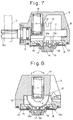
- Fig. 7 is a partially exploded side elevation view showing the main part of a conventional limit switch.
- a head 3 secured to the top of a switch case housing a basic switch mechanism has a rotary shaft 4 supported by journal bearing means 5,6 and an operating lever 7 is secured to an outer end 4a of said rotary shaft 4.
- a first cam 12 and a second cam 13 Secured to said rotary shaft 4 are a first cam 12 and a second cam 13 in juxtaposition and a cam projection 12a of said first cam 12 is set for rotation, for example in the direction of arrowmark a in Fig. 8, while a cam projection 13a of said second cam 13 is set for rotation, for example in the direction of arrowmark b in Fig. 8.
- Installed through a spring holder 11 on the flat peripheral surface of said rotary shaft 4 is a spring means 14 for applying a returning force to said operating lever 7 via said rotary shaft 4.
- a plunger holder 15 is rotatably supported by a cover plate 10, with an annular retaining spring 8 having tongue members 8a, shown in Fig. 9, being interposed between said plunger holder 15 and said cover plate 10.
- a plunger 16 associated with the first and second cams 12,13 is pivotally supported by said plunger holder 15.
- a pair of steel balls 17,18 are interposed between said plunger 16 and said first and second cams 12,13 in such a manner that the balls are free to roll.
- said steel balls 17,18 are concentrically accommodated in a pair of holding orifices 21a,21b, respectively, of a steel ball holder 21 secured to the bottom wall of said head 3, while a top wall 16g of said plunger 16 is formed with a cutout 16f for accepting either one of said steel balls 17,18 (Fig. 10).
- the plunger 16 is axially driven to turn the basic switch ON only when said operating lever 7 causes the rotary shaft 4 to turn in the direction of arrowmark a.
- the relative position of cam projections 12a,13a of said cams 12,13, said steel balls 17,18 and the cutout 16f of said plunger 16 in the above situation is diagrammatically illustrated in Fig. 11 (A).
- said plunger 16 when said plunger 16 is set in the position indicated in Fig. 11 (C), the following relation holds.
- said plunger 16 can be axially driven to turn the switch ON by rotating said operating lever 7 in whichever of the directions shown by arrowmarks a and b.
- the object of the present invention is to provide a limit switch which requires only a reduced number of parts for achieving a multiplicity of plunger drives and is easy to assemble.
- the limit switch of the present invention comprises an operating lever, a rotary shaft which is driven by said operating lever, a first cam and a second cam as mounted on said rotary shaft for transformation of rotary motion into linear motion, a return spring means for applying a returning force to said operating lever through said rotary shaft, a plunger operatively associated with said cams for turning a basic switch ON or OFF and a plunger holder for holding said plunger axially movable but not rotatable, said plunger having a plurality of integral projections corresponding to cam projections of said respective cams and disposed between the cams.
- said plunger has a plurality of integral projections, the steel balls and steel ball holder mentioned hereinbefore are no longer required so that the number of parts required is reduced and the assembling work is facilitated.
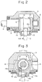
- a switch case 1 houses a basic switch 2 and a switch head 3 is securely mounted on top of the switch case 1.
- the reference numeral 4 indicates a rotary shaft which is supported by said head 3 through journal bearings 5,6, with an operating lever 7 being secured to its outer end 4a.
- a roller 9 Ratatably attached to the forward end of said operating lever 7 is a roller 9 which is abutted against an object to be detected.
- a return coil spring 14 is installed over the peripheral surfaces of said first and second cams 12,13 for applying a returning force to the operating lever 7 through these cams 12,13, with one end (not shown) thereof being secured internally of said head 3, while the other end 14a engages the cam 13.
- a plunger holder 15 is rotatably supported by a cover plate 10 secured to the bottom wall of said head 3.
- said plunger holder 15 has an axial hole 15a in which a shaft portion 16a of a plunger 16 associated with cam projections 12a,13a of said first and second cams 12,13 is installed so as to be axially movable and a recess 15b in which an approximately cruciform base 16b of said plunger 16 is unrotatably fitted (Figs. 2 and 3).
- said holder 15 is provided with a circumferentially extending engaging member 15c, with its forward projection 15d being fitted into an annular boss 3a at the bottom wall of said head 3 and disengageably held by engaging grooves 3b,3c on its inner circumferential surface.
- the base 16b of said plunger 16 has projections 16c, 16d and 16e extending radially on three mutually adjoining sides as shown in Fig. 5. Disposed within said switch case 1 between said plunger 16 and said basic switch 2 is a driving lever 20 supported by a support shaft 19.
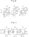
- the plunger 16 when the plunger 16 is disposed as shown with respect to the cams 12,13, the plunger 16 can be axially driven to turn the switch 2 ON only when said operating lever 7 is actuated so as to rotate the rotary shaft 4 in the direction of arrowmark a.
- the positional relationship of the cam projections 12a,13a of said first and second cams 12,13 with respect to the projections 17c through 17e of said plunger 16 is as shown diagrammatically in Fig. 6 (A), and the action here is similar to that in the condition illustrated in Fig. 11 (A) for the prior art.
- said plunger 16 when said plunger 16 is set as illustrated in Fig. 6 (C), said plunger 16 is axially driven to turn the switch 2 ON when said operating lever 7 is turned in whichever of the directions indicated by arrowmarks a and b, and the action here is similar to that in the situation illustrated in Fig. 11 (C) for the prior art.
- a variety of axial drives of the plunger 16 can be achieved according to the operating direction of the operating lever 7 by changing the relative position of the plunger 16 with respect to the cams 12,13.
- the base 16b of said plunger 16 has roof-shaped projections 16c, 16d and 16e extending radially on three mutually adjoining sides as illustrated in Fig. 5, it is no longer necessary to provide the steel balls 17,18 and steel ball holder 21 required of the prior art, thus making it possible to cut on the number of parts required and facilitating the assembling work.
- said holder 15 has a circumferentially extending engaging member 15c with its forward engaging projection 15d being fitted in the annular boss 3a of said head 3 and disengageably engaged by the engaging grooves 3b,3c on the inner circumferential surface thereof, the disposing position of said plunger 16 due to rotation of said holder 15 is limited and the positioning can be sensed from the feeling of engagement or disengagement between said engaging projection 15d and said engaging grooves 3b,3c.
Landscapes
- Engineering & Computer Science (AREA)
- Manufacturing & Machinery (AREA)
- Rotary Switch, Piano Key Switch, And Lever Switch (AREA)
- Mechanisms For Operating Contacts (AREA)
Applications Claiming Priority (2)
| Application Number | Priority Date | Filing Date | Title |
|---|---|---|---|
| JP297550/90 | 1990-11-01 | ||
| JP2297550A JP3036052B2 (ja) | 1990-11-01 | 1990-11-01 | リミツトスイツチ |
Publications (2)
| Publication Number | Publication Date |
|---|---|
| EP0483825A2 true EP0483825A2 (de) | 1992-05-06 |
| EP0483825A3 EP0483825A3 (en) | 1993-03-17 |
Family
ID=17847996
Family Applications (1)
| Application Number | Title | Priority Date | Filing Date |
|---|---|---|---|
| EP19910118561 Withdrawn EP0483825A3 (en) | 1990-11-01 | 1991-10-30 | Limit switch |
Country Status (4)
| Country | Link |
|---|---|
| US (1) | US5207316A (de) |
| EP (1) | EP0483825A3 (de) |
| JP (1) | JP3036052B2 (de) |
| KR (1) | KR920010690A (de) |
Cited By (2)
| Publication number | Priority date | Publication date | Assignee | Title |
|---|---|---|---|---|
| EP2874168A3 (de) * | 2013-10-24 | 2015-08-26 | Omron Corporation | Schalter |
| EP2804193A4 (de) * | 2012-01-13 | 2015-09-02 | Omron Tateisi Electronics Co | Begrenzungsschalter und herstellungsverfahren dafür |
Families Citing this family (10)
| Publication number | Priority date | Publication date | Assignee | Title |
|---|---|---|---|---|
| US5957273A (en) * | 1997-07-22 | 1999-09-28 | Ut Automotive Dearborn, Inc. | Universal switch |
| JP3309787B2 (ja) * | 1997-11-28 | 2002-07-29 | 株式会社豊田自動織機 | 位置検出装置及びフォークリフト用揚高位置検出装置 |
| US6126429A (en) * | 1998-06-02 | 2000-10-03 | Burger Engineering, Inc. | Combination slide retainer and position sensing switch for injection molds |
| FR2785985B1 (fr) * | 1998-11-18 | 2001-02-23 | Crouzet Automatismes | Detecteur de position avec mecanisme d'orientation |
| US6664487B2 (en) * | 2001-07-10 | 2003-12-16 | Omron Corporation | Limit switches |
| US6671929B1 (en) * | 2002-09-13 | 2004-01-06 | Shin Zu Shing Co., Ltd. | Hinge for a notebook computer |
| EP1870914A2 (de) * | 2006-06-22 | 2007-12-26 | ZIMM Maschinenelemente GmbH + Co | Endschalter mit einem Schaltteil |
| US7973257B2 (en) * | 2007-11-29 | 2011-07-05 | Sagi Faifer | Rocker switch within a device holder |
| US8317450B2 (en) * | 2008-10-30 | 2012-11-27 | Lam Research Corporation | Tactile wafer lifter and methods for operating the same |
| JP7718194B2 (ja) * | 2021-09-14 | 2025-08-05 | オムロン株式会社 | リミットスイッチ |
Family Cites Families (11)
| Publication number | Priority date | Publication date | Assignee | Title |
|---|---|---|---|---|
| US3275764A (en) * | 1964-06-05 | 1966-09-27 | Square D Co | Electric limit switch having a diagonally divided housing, a detachable actuator, and mechanisms for causing selected operation of a push button snap switch |
| US3512422A (en) * | 1968-05-31 | 1970-05-19 | Alkon Products Corp | Rotary actuator |
| US3749860A (en) * | 1971-12-30 | 1973-07-31 | Allen Bradley Co | Sealed limit switch |
| US3740504A (en) * | 1972-05-02 | 1973-06-19 | Robertshaw Controls Co | Actuator means for a switch construction and the like |
| US3959614A (en) * | 1974-10-07 | 1976-05-25 | Allen-Bradley Company | Limit switch rotary return mechanism |
| US3931484A (en) * | 1974-12-23 | 1976-01-06 | General Electric Company | Lever operated limit switch having a mechanism to increase overtravel |
| JPS5784524A (en) * | 1980-11-15 | 1982-05-26 | Omron Tateisi Electronics Co | Limit switch |
| DE3104665C2 (de) * | 1981-02-10 | 1983-01-13 | Siemens AG, 1000 Berlin und 8000 München | Betätigungsvorrichtung für einen Grenztaster |
| US4406933A (en) * | 1982-02-11 | 1983-09-27 | Square D Company | Neutral position limit switch lever head |
| GB2135517A (en) * | 1983-02-15 | 1984-08-30 | Crabtree Electrical Ind Ltd | Operating mechanism for limit switches |
| US4847453A (en) * | 1987-11-03 | 1989-07-11 | Square D Company | Limit switch with actuator |
-
1990
- 1990-11-01 JP JP2297550A patent/JP3036052B2/ja not_active Expired - Fee Related
-
1991
- 1991-10-30 US US07/785,573 patent/US5207316A/en not_active Expired - Lifetime
- 1991-10-30 EP EP19910118561 patent/EP0483825A3/en not_active Withdrawn
- 1991-10-31 KR KR1019910019241A patent/KR920010690A/ko not_active Ceased
Cited By (4)
| Publication number | Priority date | Publication date | Assignee | Title |
|---|---|---|---|---|
| EP2804193A4 (de) * | 2012-01-13 | 2015-09-02 | Omron Tateisi Electronics Co | Begrenzungsschalter und herstellungsverfahren dafür |
| US9941063B2 (en) | 2012-01-13 | 2018-04-10 | Omron Corporation | Limit switch and method for producing same |
| EP2874168A3 (de) * | 2013-10-24 | 2015-08-26 | Omron Corporation | Schalter |
| US9697960B2 (en) | 2013-10-24 | 2017-07-04 | Omron Corporation | Switch |
Also Published As
| Publication number | Publication date |
|---|---|
| US5207316A (en) | 1993-05-04 |
| JPH04169018A (ja) | 1992-06-17 |
| KR920010690A (ko) | 1992-06-27 |
| JP3036052B2 (ja) | 2000-04-24 |
| EP0483825A3 (en) | 1993-03-17 |
Similar Documents
| Publication | Publication Date | Title |
|---|---|---|
| US5207316A (en) | Limit switch | |
| EP1217496B1 (de) | Manuelle Eingabevorrichtung zum Erzeugen mehrerer Gefühlfunktionen für ihren Regelknopf und in einem Fahrzeug installiertes Steuerungsgerät darauf basierend | |
| US6688406B1 (en) | Power tool having a function control mechanism for controlling operation in one of rotary drive and hammering modes | |
| JPH06339868A (ja) | 種々の用途機構に結合可能な動力工具 | |
| JPS5915790B2 (ja) | 作業工具 | |
| US4617843A (en) | Electrically-operated driver | |
| EP3244082B1 (de) | Vorrichtung zur übertragung einer antriebskraft | |
| JPS6263246A (ja) | クラツチ装置付きシフト機構 | |
| US5562015A (en) | Automatic ratchet reversal device | |
| GB2094930A (en) | Ball screw and spline assembly | |
| US5934433A (en) | Friction clutch having an actuator for automated operation | |
| JP3300941B2 (ja) | リニアアクチュエータ | |
| JPS6358074B2 (de) | ||
| US5669453A (en) | Power carving tool | |
| JPH04171622A (ja) | リミツトスイツチ | |
| GB2095915A (en) | Limit switch assemblies | |
| US7389862B2 (en) | Continuously adjustable rotation device | |
| EP1788272B1 (de) | Kontinuierlich einstellbare Drehvorrichtung | |
| JPH04269107A (ja) | ドリル・たがね装置 | |
| JP2555472Y2 (ja) | 変速操作機構のミスシフト防止装置 | |
| EP0861996A1 (de) | Vorrichtung zur umwandlung einer rotierenden bewegung in eine lineare bewegung | |
| JPH11149847A (ja) | リミットスイッチ | |
| JPS6315646Y2 (de) | ||
| US7511241B1 (en) | Rotary indexing mechanism for a mechanically activated control | |
| JPH0532338Y2 (de) |
Legal Events
| Date | Code | Title | Description |
|---|---|---|---|
| PUAI | Public reference made under article 153(3) epc to a published international application that has entered the european phase |
Free format text: ORIGINAL CODE: 0009012 |
|
| 17P | Request for examination filed |
Effective date: 19911127 |
|
| AK | Designated contracting states |
Kind code of ref document: A2 Designated state(s): AT BE CH DE DK ES FR GB GR IT LI NL SE |
|
| PUAL | Search report despatched |
Free format text: ORIGINAL CODE: 0009013 |
|
| AK | Designated contracting states |
Kind code of ref document: A3 Designated state(s): AT BE CH DE DK ES FR GB GR IT LI NL SE |
|
| 17Q | First examination report despatched |
Effective date: 19940117 |
|
| STAA | Information on the status of an ep patent application or granted ep patent |
Free format text: STATUS: THE APPLICATION IS DEEMED TO BE WITHDRAWN |
|
| 18D | Application deemed to be withdrawn |
Effective date: 19950322 |