EP0484526A1 - Vorrichtung zum steuern eines motors mit änderlichem vermögen für ein hydraulisch angetriebenes fahrzeug - Google Patents
Vorrichtung zum steuern eines motors mit änderlichem vermögen für ein hydraulisch angetriebenes fahrzeug Download PDFInfo
- Publication number
- EP0484526A1 EP0484526A1 EP90908653A EP90908653A EP0484526A1 EP 0484526 A1 EP0484526 A1 EP 0484526A1 EP 90908653 A EP90908653 A EP 90908653A EP 90908653 A EP90908653 A EP 90908653A EP 0484526 A1 EP0484526 A1 EP 0484526A1
- Authority
- EP
- European Patent Office
- Prior art keywords
- pressure
- motor
- hydraulic
- control
- variable capacity
- Prior art date
- Legal status (The legal status is an assumption and is not a legal conclusion. Google has not performed a legal analysis and makes no representation as to the accuracy of the status listed.)
- Granted
Links
Images


Classifications
-
- F—MECHANICAL ENGINEERING; LIGHTING; HEATING; WEAPONS; BLASTING
- F16—ENGINEERING ELEMENTS AND UNITS; GENERAL MEASURES FOR PRODUCING AND MAINTAINING EFFECTIVE FUNCTIONING OF MACHINES OR INSTALLATIONS; THERMAL INSULATION IN GENERAL
- F16H—GEARING
- F16H61/00—Control functions within control units of change-speed- or reversing-gearings for conveying rotary motion ; Control of exclusively fluid gearing, friction gearing, gearings with endless flexible members or other particular types of gearing
- F16H61/38—Control of exclusively fluid gearing
- F16H61/40—Control of exclusively fluid gearing hydrostatic
- F16H61/46—Automatic regulation in accordance with output requirements
-
- F—MECHANICAL ENGINEERING; LIGHTING; HEATING; WEAPONS; BLASTING
- F16—ENGINEERING ELEMENTS AND UNITS; GENERAL MEASURES FOR PRODUCING AND MAINTAINING EFFECTIVE FUNCTIONING OF MACHINES OR INSTALLATIONS; THERMAL INSULATION IN GENERAL
- F16H—GEARING
- F16H61/00—Control functions within control units of change-speed- or reversing-gearings for conveying rotary motion ; Control of exclusively fluid gearing, friction gearing, gearings with endless flexible members or other particular types of gearing
- F16H61/38—Control of exclusively fluid gearing
- F16H61/40—Control of exclusively fluid gearing hydrostatic
- F16H61/42—Control of exclusively fluid gearing hydrostatic involving adjustment of a pump or motor with adjustable output or capacity
- F16H61/423—Motor capacity control by fluid pressure control means
Definitions
- the present invention relates to a device for controlling a variable capacity motor incorporated in an industrial vehicle provided with shovel loader etc., and particularly to the device which is effectively incorporated in an infinite variable-speed hydraulic drive vehicle in which the maximum traveling speed of the vehicle should be controlled in response to a working condition.
- Illustrated in Fig. 13 is a conventional hydraulic circuit of an infinite variable-speed hydraulic drive vehicle which has a variable capacity hydraulic pump and a motor.
- a part of the output of an engine 5 drives a working machine hydraulic pump 4 and acts upon a working machine hydraulic cylinder 52 by way of a working machine hydraulic circuit 51.
- Remaining output of the engine 5 drives the control pump 3 and a hydraulic pump 1 in which oil pressure is generated.
- the oil pressure thus generated at the hydraulic pump 1 flows through main circuits 24 and 25, rotates the variable capacity motor 2, thereby forming a driving force.
- Designated at 6 is a pump control valve for controlling the capacity of the hydraulic pump 1
- 7 is a pump capacity control cylinder
- 8, 8 are main relief valves
- 10 is a filter.
- Oil under pressure which flows from the pump control valve 6 to the motor control oil line 11, is introduced into one end of the motor control valve 14, whereby the oil introduced into the motor control valve 14 operates to introduce the oil under high pressure, which is introduced by a pilot hydraulic piping 16 from the main circuits 24 and 25, into a motor capacity control cylinder 31.
- the pump capacity control cylinder 7 and a motor capacity control cylinder 31 are controlled by the pump control valve 6 and the motor control valve 14 so that the capacity of the pump 1 and the capacity of the hydraulic motor 2 are arbitrarily varied, thereby varying the traveling speed of the vehicle.
- a graph representing a traveling performance curve of the conventional hydraulic drive vehicle, as explained in Fig. 13, will be described with reference to Fig. 14.
- both the traveling driving force and the traveling speed are continuously varied so that they are automatically and continuously varied without changing operation from the maximum driving force (traveling speed is 0) to the maximum speed. Accordingly, since the driver can control the traveling speed and the driving force, it is possible to travel the vehicle easier than a vehicle provided with a mechanical speed change gear.
- the conventional hydraulic drive vehicle has an advantage that the traveling operation is easy.
- the working machine pump 4 of the loader is also driven by the engine in the same way as the hydraulic drive pump 1. Since the maximum rising speed of the loader is proportional to the engine speed, the rising speed of the loader is also controlled by the travel of the accelerator pedal in the same way as the traveling speed. Accordingly, in case that the hydraulic drive vehicle travels while raising the loader at the narrow working site, the working efficiency is improved, when the loader rises at the maximum speed and the vehicle travels at low speed.
- Pst1'', ........ Pst5'' represent pressures of a pilot hydraulic piping 15.
- the relation between the capacity of the motor (horizontal axis) and the pressure P H '' (vertical axis) in the main hydraulic circuits 24 and 25 is varied by the pilot pressures Pst1'' ........ Pst5''.
- the traveling speed is accelerated at full throttle so as to rise the loader at the maximum speed, as the pilot pressure rises to Pst1'' and thereafter the traveling load decreases, the pressure P H '' decreases as the traveling load decreases.
- the traveling speed increases as the capacity of the motor moves along the characteristic line of the pilot pressure and reaches the minimum.
- the traveling speed reaches the maximum speed, which causes the problem in the working site having small traveling range.
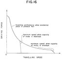
- the multiple speed gear change method is conventionally employed wherein the maximum traveling speed is reduced while the capacity of the motor is fixed to be the maximum or the mechanical speed change gear is connected to the motor.
- the traveling speed is limited to the low speed since the capacity of the motor is fixed as illustrated in Fig. 16 and a problem in the latter that the device cannot match exactly with the working condition since the maximum driving force is not obtained at high range as illustrated in Fig. 17.
- the applicant proposed a means, which is disclosed in Japanese Utility Application No.
- a motor control valve 14 of this device controls the motor control oil pressure by balancing the control oil pressure with the main circuit oil pressure, but it had the following problems.
- the present invention is to provide a device for controlling the variable capacity motor incorporated in a hydraulic drive vehicle, wherein a means for reducing the oil pressure for controlling the motor is provided to pilot hydraulic piping from a control pump for controlling the capacity of the variable capacity motor, and solenoid changeover valves are provided for performing changeover between operation and non-operation of the pressure reduction means.
- the device having such an arrangement serves to continuously control the minimum capacity of the variable capacity hydraulic motor while reducing the pressure of pilot oil introduced from the control pump.
- the changeover valves operate, even when the pressure reduction means is in operation, so as to control to cancel the operation of the pressure reduction means for continuously controlling the maximum traveling speed.
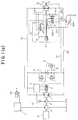
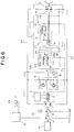
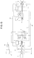
- Fig. 1(a) is a hydraulic circuit diagram of an infinite variable-speed hydraulic drive vehicle employing a variable capacity hydraulic pump and a motor according to an embodiment of the present invention
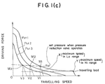
- Fig. 1(b) is a graph showing an operation of the device
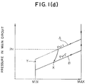
- Figs. 1(c) and 1(d) are graphs showing various characteristic of pressures
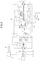
- Figs 2 to 6 are hydraulic circuit diagrams according to other embodiments of the present invention
- Fig. 7 is a graph showing a characteristic of a pressure control valve in Fig. 6
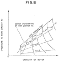
- Fig. 8 is a graph showing a control characteristic of the variable capacity hydraulic motor of the hydraulic circuit in Fig. 6
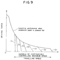
- Fig. 9 is a graph showing the control of the maximum traveling speed of the hydraulic drive vehicle employing the hydraulic circuit in Fig. 6,
- Figs. 10 and 11 are views showing other embodiments of a traveling speed cut-off device and
- Figs. 12 to 17 are views showing conventional device and characteristics thereof.
- Fig. 1(a) is a hydraulic circuit diagram of an infinite variable-speed hydraulic drive vehicle employing a variable capacity hydraulic pump and a motor according to an embodiment of the present invention, in which elements same as those in the conventional hydraulic circuit shown in Fig. 13 are denoted at the same numerals and explanations thereof are omitted.
- a main feature of the hydraulic circuit as illustrated in Fig. 1 (a) resides in that a traveling speed cut-off device 200 is added to the conventional hydraulic circuit as illustrated in Fig. 13.
- a pressure reduction valve 201 is provided at a pilot hydraulic piping 15 which supplies a pressurized oil from the control pump 3 to the motor control valve 14 so that the pilot pressure to be applied to the motor control valve 14 is reduced.
- a solenoid changeover valve 202 is provided for performing changeover between operation and non-operation of the pressure reduction means 201.
- a changeover valve 203 is also provided for changing the pressure reduction valve 201 from operation state to non-operation state if the pressure in the main circuit exceeds a preset value P H1 even if the pressure reduction valve 201 is changed overby the changeover valve 202 from the non-operation state to the operation state.
- a resilient force of a pressure regulating spring of the pressure reduction valve 201 and a resilient force of a set pressure adjusting spring of the changeover valve 203 can be arbitrarily adjusted.
- the pressure P H1 in the main circuit is a set pressure of the changeover valve 203, hence the pressure reduction valve 201 does not operate when the set pressure is higher than the pressure P H1 in the main circuit so that the relation represented by the straight-lines P st 1, P st 2 . « is established whichever the solenoid changeover valve 202 is closed or open.
- the traveling performance depends on a control characteristic of the motor and represented as illustrated in Fig. 1(c). At the set pressure P H1 of the changeover valve 203, the traveling speed are represented as V1, V2 and V3.
- the traveling performance is constant irrespective of the state of the solenoid changeover valve 202.
- the driving force is less than the matching point M1
- the pressure reduction valve operates when the solenoid changeover valve 202 is opened, hence the characteristic of the motor is represented as P st 1', P st 2' (2003)
- the traveling performance is represented as illustrated in the broken lines in Fig. 1(b), whereby the maximum traveling speed is controlled.
- Fig. 1(d) is a graph showing a change of the capacity of the motor when the solenoid changeover valve 202 is opened and the control pressure is represented as P st1 , in the hydraulic circuit as illustrated in Fig. 1(a).
- the characteristic of the motor is represented as A. Since the control pressure is reduced when the pressure in the main circuit is less than the set value, the capacity of the motor is not varied to the minimum capacity but is reduced to the capacity where the motor capacity and the traveling pressure balances finally (X point) and is stabilized there.
- the capacity of the motor moves along the straight line of the pressure P st1 and is varied to the minimum capacity of the motor and is finally varied to the point (Y) where it balances with the traveling pressure at the maximum traveling speed.
- a ratio of the capacity of the motor at the point X relative to that at the point Y determines the upper limit traveling speed of the low range speed (point X in Fig. 1(c)).
- a characteristic B in Fig. 1(d) represents the characteristic of the motor when the traveling load is varied from the low to the high load, namely, the traveling speed is varied from the high speed (point X) to the low speed.
- Figs. 2 and 3 show another embodiment according to the present invention.
- a throttle valve 301 is provided at the pilot hydraulic piping 15 instead of the pressure reduction valve.
- a bypass circuit 317 which communicates with a tank at the downstream of the throttle valve 301 and another throttle valve 305 which is positioned in the bypass circuit 317.
- a solenoid changeover valve 302 and a pilot hydraulic changeover valve 303 operate in the same way as the pressure reduction valve 201 as illustrated in Fig. 1(a) and are serially provided at the upper stream or the lowerstream of the throttle valve 305.
- a throttle valve 401 is provided at the pilot hydraulic piping 15 instead of the pressure reduction valve.
- a bypass circuit 417 which communicates with the tank at the downstream of the throttle valve 401 and a pressure regulating valve 406 which is positioned at the bypass circuit 417.
- the oil under pressure which is regulated by the pressure regulating valve 406 is supplied to the motor control valve 14 and the pressure of the oil in the upstream is reduced by the throttle valve 401.
- a solenoid changeover valve 402 and a hydraulic pilot changeover valve 403 operate in the same way as the pressure reduction valve 201 as illustrated in Fig. 1(a) and are provided serially at the upperstream or the downstream of the pressure regulating valve 406.
- a pressure detector 507 for detecting the oil pressure of the main circuit and a control circuit for switching over and controlling a solenoid changeover valve 502 by the operation of the pressure detector 507, instead of the pilot hydraulic changeover valves in Figs. 1(a), 2 and 3.
- the changeover valve 502 is switched over to the direction where a pressure reduction means of the solenoid changeover valve 502 operates only at the time when the pressure is less than the preset value of the pressure in the main circuit in the same way as the pilot hydraulic changeover valve.
- a traveling speed detector 608 for detecting the traveling speed and a control unit 609 for switching over and controlling a solenoid valve 602 in response to a signal issued by the traveling speed detector 608 wherein the changeover valve solenoid valve 602 is switched over to the direction where the pressure reduction means operates when the traveling speed exceeds over the preset value of a low speed range in the same way as the pilot hydraulic changeover valve.
- the maximum speed in the low speed range can be regulated by sectional areas of the throttle valves 301 and 305 and regulating pressure by the changeover valve 303 in the embodiment of Fig. 2, by regulating pressures by the pressure regulating valve 406 and the changeover valve 403 in the embodiment of Fig. 3, by regulating pressure by the pressure reduction means and set-value of the main circuit which is detected by the pressure detector in the embodiment of Fig. 4 and by regulating pressure by the reduction means and the traveling speed control valve by the control unit 609 respectively.
- pressure reduction means which are controlled by the pressure detector in the main circuit or the traveling speed detector can be replaced by a solenoid pressure reduction valve (in the embodiment of Fig. 1(a)), a solenoid throttle valve (in the embodiment of Fig. 2) and a solenoid pressure regulating valve (in the embodiment of Fig. 3) all of which operate in the same manner as these pressure reduction means.
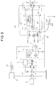
- Fig. 6 is a view showing other embodiment of the present invention. Components same as those in Fig. 13 are denoted at same numerals and the explanation thereof are omitted.
- a feature of this embodiment resides in adding a traveling speed cut-off device 222 to the conventional hydraulic circuit as illustrated in Fig. 13.
- This embodiment comprises the pilot hydraulic piping 15 which supplies the oil under pressure from the control pump 3 to the motor control valve 14, a pilot hydraulic piping 217 which extends from the pilot hydraulic piping 15 and is connected to one end of a pressure reduction type pressure control valve 219 and a pilot hydraulic piping 218 which supplies the oil under pressure from the main circuit 24 or 25 at the high pressure side to the motor control valve 14 is connected to another end of the reduction type pressure control valve 219.
- the pressure control valve 219 is balanced by difference between the pressure in the pilot hydraulic piping 217 and the pressure in the pilot hydraulic piping 218 and a spring 220. Resilience force of the spring 220 can be arbitrarily adjusted by a lever 221.
- main circuit pressure a pressure P H of the main circuit 24 or 25 at the high pressure side
- main circuit pressure a pressure P H of the main circuit 24 or 25 at the high pressure side
- P st is a control pressure in the pilot hydraulic piping 217
- F is a resilient force of the spring 220
- B is an area of the pressure control valve 219 for receiving the pressure at the side of the pilot hydraulic piping 218, and
- A is an area of the pressure control valve 219 for receiving the pressure at the pilot hydraulic piping 217.
- a characteristic of the pressure control valve 219 is illustrated in Fig. 7.
- straight lines X1, X2, X3 .... . show the characteristic when the pressure regulating valve 219 is switched over from the position 219a to the position 219b, which is continuously varied when the spring 220 is operated by the lever 221.
- a graph in Fig. 8 represents the relation between the main circuit pressure P H in the hydraulic circuit in Fig. 6, the capacity of the motor and the pilot pressure P st , i.e. the control characteristic of the variable capacity hydraulic motor 2 and corresponds to the graph in Fig. 15 of the conventional hydraulic circuit in Fig. 13.
- the capacity of the motor is minimum at the matching lines Y1, Y2, Y3.... . Since the minimum capacity of the motor can be controlled arbitrarily, it is possible to control the maximum traveling speed continuously between Z1 to Z7 as illustrated in Fig. 9.
- Fig. 10 is a view showing still other embodiment of the present invention.
- a traveling speed cut-off device 222' is illustrated in which the traveling speed cut-off device 222 in Fig. 6 is replaced by the traveling speed cut-off device 222' and a pressure reduction type solenoid pressure control valve 219 in Fig. 6 is replaced by the same as denoted at 219' and the lever 221 in Fig. 6 is replaced by a control device 221'.
- the same characteristic as illustrated in Fig. 8 is obtained in response to the instruction current by the control device 221'.
- Fig. 11 is a view of still other embodiment of the present invention.
- a traveling speed cut-off device 222'' is illustrated in which the traveling speed cut-off device 222 in Fig. 6 is replaced by the traveling speed cut-off device 222'' and the lever 221 in Fig. 6 is replaced by a solenoid changeover valve 226'' and a changeover switch 221'', wherein the changeover switch 221'' is switched over so as to switch over to only one of positions in Fig. 8.
- pressure reduction type pressure control valve is provided in series in the motor control circuit, when the pressure regulating valve is positioned at the position 219b (when pressure is reduced), it is possible to lessen the pressure reduction in the upstream circuit, which dispenses with a fixed orifice, thereby improving a response of the variation of the capacity of the motor relative to the variation of the motor control pressure.
- the matching between the traveling speed and the loading speed are suitably made under the working condition.
- the traveling performance is not influenced by the variation of the main circuit pressure, hence is suitably employed in the device for controlling variable capacity motor of hydraulic drive vehicle , the maximum traveling speed of which should be controlled in response to the working condition.
Landscapes
- Engineering & Computer Science (AREA)
- General Engineering & Computer Science (AREA)
- Mechanical Engineering (AREA)
- Physics & Mathematics (AREA)
- Fluid Mechanics (AREA)
- Control Of Fluid Gearings (AREA)
- Operation Control Of Excavators (AREA)
Applications Claiming Priority (5)
| Application Number | Priority Date | Filing Date | Title |
|---|---|---|---|
| JP145057/89 | 1989-06-09 | ||
| JP14505789A JPH0314966A (ja) | 1989-06-09 | 1989-06-09 | 油圧駆動車の可変容量モータ制御装置 |
| JP119729/89U | 1989-10-16 | ||
| JP1989119729U JPH0740764Y2 (ja) | 1989-10-16 | 1989-10-16 | 油圧駆動車両の可変容量油圧モータ制御装置 |
| PCT/JP1990/000747 WO1990015270A1 (fr) | 1989-06-09 | 1990-06-08 | Dispositif de commande d'un moteur a capacite variable d'un vehicule a entrainement hydraulique |
Publications (3)
| Publication Number | Publication Date |
|---|---|
| EP0484526A1 true EP0484526A1 (de) | 1992-05-13 |
| EP0484526A4 EP0484526A4 (en) | 1992-05-27 |
| EP0484526B1 EP0484526B1 (de) | 1995-11-15 |
Family
ID=26457407
Family Applications (1)
| Application Number | Title | Priority Date | Filing Date |
|---|---|---|---|
| EP90908653A Expired - Lifetime EP0484526B1 (de) | 1989-06-09 | 1990-06-08 | Vorrichtung zum steuern eines motors mit änderlichem vermögen für ein hydraulisch angetriebenes fahrzeug |
Country Status (6)
| Country | Link |
|---|---|
| US (1) | US5299421A (de) |
| EP (1) | EP0484526B1 (de) |
| KR (1) | KR920701724A (de) |
| AU (1) | AU5741390A (de) |
| DE (1) | DE69023651T2 (de) |
| WO (1) | WO1990015270A1 (de) |
Cited By (4)
| Publication number | Priority date | Publication date | Assignee | Title |
|---|---|---|---|---|
| DE19509869A1 (de) * | 1995-03-17 | 1996-09-26 | Sauer Sundstrand Gmbh & Co | Steuer- und Regelsystem für ein automotives hydrostatisches Getriebe |
| EP0766025A1 (de) * | 1995-09-27 | 1997-04-02 | O&K ORENSTEIN & KOPPEL AG | Verfahren zur Steuerung der Schaltzustände eines stufenlos regelbaren hydrostatischen Fahrantriebes |
| WO2000026563A1 (de) * | 1998-10-30 | 2000-05-11 | Brueninghaus Hydromatik Gmbh | Hydrostatisches getriebe |
| DE102014220855A1 (de) * | 2014-10-15 | 2016-05-04 | Robert Bosch Gmbh | Hydrostatischer Fahrantrieb |
Families Citing this family (4)
| Publication number | Priority date | Publication date | Assignee | Title |
|---|---|---|---|---|
| EP1442240A1 (de) * | 2001-10-12 | 2004-08-04 | Clark Equipment Company | Betrieb einer mit rädern versehenen arbeitsmaschine |
| JP5074086B2 (ja) * | 2007-04-26 | 2012-11-14 | 株式会社小松製作所 | 建設車両 |
| JP5274581B2 (ja) * | 2008-12-17 | 2013-08-28 | 株式会社小松製作所 | 静油圧式変速車両の制御装置 |
| JP5072926B2 (ja) | 2009-09-03 | 2012-11-14 | 株式会社小松製作所 | 作業車両 |
Family Cites Families (15)
| Publication number | Priority date | Publication date | Assignee | Title |
|---|---|---|---|---|
| DE1751471A1 (de) * | 1968-06-05 | 1971-05-19 | Bosch Gmbh Robert | Steuer- und Regeleinrichtung fuer ein hydrostatisches Getriebe |
| US3877224A (en) * | 1973-12-21 | 1975-04-15 | Caterpillar Tractor Co | Single pump hydrostatic transmission control and supply system |
| DE2449464A1 (de) * | 1974-10-19 | 1976-05-06 | Kloeckner Humboldt Deutz Ag | Hydrostatisches fahrzeuggetriebe |
| DE2522719C2 (de) * | 1975-05-22 | 1986-06-05 | Linde Ag, 6200 Wiesbaden | Steuereinrichtung |
| CA1214088A (en) * | 1978-12-08 | 1986-11-18 | William S. Heggie | Engine control systems |
| US4399886A (en) * | 1980-12-09 | 1983-08-23 | Sundstrand Corporation | Controls for variable displacement motor and motors |
| JPS57134063A (en) * | 1981-02-10 | 1982-08-19 | Hitachi Constr Mach Co Ltd | Controller for hydraulic system equipped with plural number of motor |
| US4530416A (en) * | 1983-05-23 | 1985-07-23 | Fmc Corporation | Hydrostatic propulsion system and method with inching throttle and brake |
| US4554991A (en) * | 1984-02-23 | 1985-11-26 | Mud Hog Corporation | Auxiliary hydraulic drive system for road graders and the like |
| JPS618307A (ja) * | 1984-06-25 | 1986-01-16 | 松下電工株式会社 | 単板の製法 |
| JPS6213543A (ja) * | 1985-07-11 | 1987-01-22 | Sumitomo Metal Mining Co Ltd | 自溶炉の操業方法 |
| GB2204652B (en) * | 1987-05-09 | 1991-05-15 | Kubota Ltd | Fluid pressure control circuit for working vehicle having transmission operable by fluid pressure |
| DE3742569A1 (de) * | 1987-12-16 | 1989-07-06 | Klemm Gerhard Maschfab | Hydromechanische antriebsuebertragungsvorrichtung, wie kupplung, getriebe oder dgl. |
| JPH0265757A (ja) * | 1988-09-01 | 1990-03-06 | Samusan Kk | 無臭にんにく及び無臭にんにく液 |
| JP2525386Y2 (ja) * | 1988-11-08 | 1997-02-12 | 株式会社 小松製作所 | 油圧駆動車両の可変容量油圧モータ制御装置 |
-
1990
- 1990-06-08 EP EP90908653A patent/EP0484526B1/de not_active Expired - Lifetime
- 1990-06-08 KR KR1019910701811A patent/KR920701724A/ko not_active Ceased
- 1990-06-08 US US07/778,922 patent/US5299421A/en not_active Expired - Lifetime
- 1990-06-08 DE DE69023651T patent/DE69023651T2/de not_active Expired - Fee Related
- 1990-06-08 AU AU57413/90A patent/AU5741390A/en not_active Abandoned
- 1990-06-08 WO PCT/JP1990/000747 patent/WO1990015270A1/ja not_active Ceased
Cited By (6)
| Publication number | Priority date | Publication date | Assignee | Title |
|---|---|---|---|---|
| DE19509869A1 (de) * | 1995-03-17 | 1996-09-26 | Sauer Sundstrand Gmbh & Co | Steuer- und Regelsystem für ein automotives hydrostatisches Getriebe |
| DE19509869B4 (de) * | 1995-03-17 | 2005-11-03 | Sauer-Danfoss Gmbh & Co Ohg | Steuer- und Regelsystem für ein automotives hydrostatisches Getriebe |
| EP0766025A1 (de) * | 1995-09-27 | 1997-04-02 | O&K ORENSTEIN & KOPPEL AG | Verfahren zur Steuerung der Schaltzustände eines stufenlos regelbaren hydrostatischen Fahrantriebes |
| WO2000026563A1 (de) * | 1998-10-30 | 2000-05-11 | Brueninghaus Hydromatik Gmbh | Hydrostatisches getriebe |
| US6351945B1 (en) | 1998-10-30 | 2002-03-05 | Brueninghaus Hydromatik Gmbh | Hydrostatic gear unit |
| DE102014220855A1 (de) * | 2014-10-15 | 2016-05-04 | Robert Bosch Gmbh | Hydrostatischer Fahrantrieb |
Also Published As
| Publication number | Publication date |
|---|---|
| EP0484526B1 (de) | 1995-11-15 |
| DE69023651D1 (de) | 1995-12-21 |
| AU5741390A (en) | 1991-01-07 |
| WO1990015270A1 (fr) | 1990-12-13 |
| US5299421A (en) | 1994-04-05 |
| KR920701724A (ko) | 1992-08-12 |
| EP0484526A4 (en) | 1992-05-27 |
| DE69023651T2 (de) | 1996-05-02 |
Similar Documents
| Publication | Publication Date | Title |
|---|---|---|
| EP0765970B1 (de) | Hydraulische Steuervorrichtung für eine Baumaschine | |
| EP0532756B1 (de) | Vorrichtung und verfahren zum steuern eines ladefahrzeuges | |
| US5148676A (en) | Confluence valve circuit of a hydraulic excavator | |
| KR100207928B1 (ko) | 유압구동장치 | |
| US6220028B1 (en) | Hydraulic drive system for hydraulic work vehicle | |
| EP0287670A1 (de) | Steuerregelungsvorrichtung für hydraulische konstruktionsmaschinen | |
| KR100655353B1 (ko) | 짐싣기 작업차량 | |
| US4976106A (en) | Load-sensing variable displacement pump controller with adjustable pressure-compensated flow control valve in feedback path | |
| KR920007650B1 (ko) | 작업기계의 유압회로장치 | |
| EP0484526A1 (de) | Vorrichtung zum steuern eines motors mit änderlichem vermögen für ein hydraulisch angetriebenes fahrzeug | |
| US4884475A (en) | Automotive drive system for machines and vehicles | |
| US5291676A (en) | Hydraulic drive system | |
| JP3003958B2 (ja) | ロードセンシング油圧回路 | |
| JPH07119506A (ja) | 油圧建設機械の原動機回転数制御装置 | |
| JPH0579502A (ja) | 油圧建設機械 | |
| KR100256897B1 (ko) | 유압작업기의엔진회전수의제어장치 | |
| EP0396781B1 (de) | Regelungsverfahren für einen hydraulischen motor mit veränderlicher kapazität bei einem hydraulisch angetriebenen fahrzeug | |
| JPH11132154A (ja) | 作業車両用作業機ポンプの容量制御装置 | |
| JPH05215101A (ja) | ポンプ傾転量の制御方法 | |
| KR0168991B1 (ko) | 유압식 건설기계의 전자제어장치 | |
| KR960004409B1 (ko) | 굴삭기의 유압제어 방법 및 장치 | |
| JPH0740764Y2 (ja) | 油圧駆動車両の可変容量油圧モータ制御装置 | |
| JPH07190004A (ja) | 建設機械の油圧制御装置 | |
| JPH0754146B2 (ja) | 油圧駆動回路 | |
| JPH08165680A (ja) | 油圧ショベルの発電機駆動装置 |
Legal Events
| Date | Code | Title | Description |
|---|---|---|---|
| PUAI | Public reference made under article 153(3) epc to a published international application that has entered the european phase |
Free format text: ORIGINAL CODE: 0009012 |
|
| 17P | Request for examination filed |
Effective date: 19911209 |
|
| AK | Designated contracting states |
Kind code of ref document: A1 Designated state(s): DE SE |
|
| A4 | Supplementary search report drawn up and despatched |
Effective date: 19920406 |
|
| AK | Designated contracting states |
Kind code of ref document: A4 Designated state(s): DE SE |
|
| 17Q | First examination report despatched |
Effective date: 19940114 |
|
| GRAA | (expected) grant |
Free format text: ORIGINAL CODE: 0009210 |
|
| AK | Designated contracting states |
Kind code of ref document: B1 Designated state(s): DE SE |
|
| REF | Corresponds to: |
Ref document number: 69023651 Country of ref document: DE Date of ref document: 19951221 |
|
| PLBE | No opposition filed within time limit |
Free format text: ORIGINAL CODE: 0009261 |
|
| STAA | Information on the status of an ep patent application or granted ep patent |
Free format text: STATUS: NO OPPOSITION FILED WITHIN TIME LIMIT |
|
| 26N | No opposition filed | ||
| PGFP | Annual fee paid to national office [announced via postgrant information from national office to epo] |
Ref country code: SE Payment date: 19970618 Year of fee payment: 8 |
|
| PG25 | Lapsed in a contracting state [announced via postgrant information from national office to epo] |
Ref country code: SE Free format text: LAPSE BECAUSE OF NON-PAYMENT OF DUE FEES Effective date: 19980609 |
|
| EUG | Se: european patent has lapsed |
Ref document number: 90908653.0 |
|
| PGFP | Annual fee paid to national office [announced via postgrant information from national office to epo] |
Ref country code: DE Payment date: 20020612 Year of fee payment: 13 |
|
| PG25 | Lapsed in a contracting state [announced via postgrant information from national office to epo] |
Ref country code: DE Free format text: LAPSE BECAUSE OF NON-PAYMENT OF DUE FEES Effective date: 20040101 |