EP0484556A1 - Werkzeugmaschine - Google Patents
Werkzeugmaschine Download PDFInfo
- Publication number
- EP0484556A1 EP0484556A1 EP91909719A EP91909719A EP0484556A1 EP 0484556 A1 EP0484556 A1 EP 0484556A1 EP 91909719 A EP91909719 A EP 91909719A EP 91909719 A EP91909719 A EP 91909719A EP 0484556 A1 EP0484556 A1 EP 0484556A1
- Authority
- EP
- European Patent Office
- Prior art keywords
- pallet
- arm
- machine tool
- workpiece
- exchanging
- Prior art date
- Legal status (The legal status is an assumption and is not a legal conclusion. Google has not performed a legal analysis and makes no representation as to the accuracy of the status listed.)
- Withdrawn
Links
- 238000003754 machining Methods 0.000 claims description 17
- 239000010730 cutting oil Substances 0.000 abstract description 7
- 230000005540 biological transmission Effects 0.000 description 6
- 230000033001 locomotion Effects 0.000 description 6
- 238000010276 construction Methods 0.000 description 5
- 230000008602 contraction Effects 0.000 description 3
- 238000006073 displacement reaction Methods 0.000 description 2
- 239000000284 extract Substances 0.000 description 2
- 244000182067 Fraxinus ornus Species 0.000 description 1
- 238000004140 cleaning Methods 0.000 description 1
- 230000008878 coupling Effects 0.000 description 1
- 238000010168 coupling process Methods 0.000 description 1
- 238000005859 coupling reaction Methods 0.000 description 1
- 230000008021 deposition Effects 0.000 description 1
- 239000000428 dust Substances 0.000 description 1
- 230000000694 effects Effects 0.000 description 1
- 239000003921 oil Substances 0.000 description 1
- 230000001131 transforming effect Effects 0.000 description 1
- 238000012384 transportation and delivery Methods 0.000 description 1
Images




Classifications
-
- B—PERFORMING OPERATIONS; TRANSPORTING
- B23—MACHINE TOOLS; METAL-WORKING NOT OTHERWISE PROVIDED FOR
- B23Q—DETAILS, COMPONENTS, OR ACCESSORIES FOR MACHINE TOOLS, e.g. ARRANGEMENTS FOR COPYING OR CONTROLLING; MACHINE TOOLS IN GENERAL CHARACTERISED BY THE CONSTRUCTION OF PARTICULAR DETAILS OR COMPONENTS; COMBINATIONS OR ASSOCIATIONS OF METAL-WORKING MACHINES, NOT DIRECTED TO A PARTICULAR RESULT
- B23Q7/00—Arrangements for handling work specially combined with or arranged in, or specially adapted for use in connection with, machine tools, e.g. for conveying, loading, positioning, discharging, sorting
- B23Q7/14—Arrangements for handling work specially combined with or arranged in, or specially adapted for use in connection with, machine tools, e.g. for conveying, loading, positioning, discharging, sorting co-ordinated in production lines
- B23Q7/1426—Arrangements for handling work specially combined with or arranged in, or specially adapted for use in connection with, machine tools, e.g. for conveying, loading, positioning, discharging, sorting co-ordinated in production lines with work holders not rigidly fixed to the transport devices
-
- B—PERFORMING OPERATIONS; TRANSPORTING
- B23—MACHINE TOOLS; METAL-WORKING NOT OTHERWISE PROVIDED FOR
- B23Q—DETAILS, COMPONENTS, OR ACCESSORIES FOR MACHINE TOOLS, e.g. ARRANGEMENTS FOR COPYING OR CONTROLLING; MACHINE TOOLS IN GENERAL CHARACTERISED BY THE CONSTRUCTION OF PARTICULAR DETAILS OR COMPONENTS; COMBINATIONS OR ASSOCIATIONS OF METAL-WORKING MACHINES, NOT DIRECTED TO A PARTICULAR RESULT
- B23Q11/00—Accessories fitted to machine tools for keeping tools or parts of the machine in good working condition or for cooling work; Safety devices specially combined with or arranged in, or specially adapted for use in connection with, machine tools
- B23Q11/0042—Devices for removing chips
-
- B—PERFORMING OPERATIONS; TRANSPORTING
- B23—MACHINE TOOLS; METAL-WORKING NOT OTHERWISE PROVIDED FOR
- B23Q—DETAILS, COMPONENTS, OR ACCESSORIES FOR MACHINE TOOLS, e.g. ARRANGEMENTS FOR COPYING OR CONTROLLING; MACHINE TOOLS IN GENERAL CHARACTERISED BY THE CONSTRUCTION OF PARTICULAR DETAILS OR COMPONENTS; COMBINATIONS OR ASSOCIATIONS OF METAL-WORKING MACHINES, NOT DIRECTED TO A PARTICULAR RESULT
- B23Q7/00—Arrangements for handling work specially combined with or arranged in, or specially adapted for use in connection with, machine tools, e.g. for conveying, loading, positioning, discharging, sorting
- B23Q7/10—Arrangements for handling work specially combined with or arranged in, or specially adapted for use in connection with, machine tools, e.g. for conveying, loading, positioning, discharging, sorting by means of magazines
Definitions
- the present invention relates to a machine tool wherein the pallet with a workpiece fixed thereto is clamped by the clamping device for machining the workpiece.
- Such a machine tool is already widely utilized as provided with a pallet changer adapted to mount the pallet having a workpiece that is to be machined to the machine tool and to remove the pallet holding the workpiece that has been machined from the machine tool and the workpiece mounted on the pallet which is clamped by means of a clamping device may be machined.
- the pallet which is to be exchangeably attached to the machine tool by means of a pallet changer will be attached to a horizontal table or an index table.
- a machine tool including a clamping device adapted to clamp the pallet having a workpiece fixed thereto and a spindle head adapted to attach the cutting tool for machining the workpiece held by the clamping device, wherein said clamping device is so constructed as to be mounted to the machine tool from the lower side and the workpiece is held on the lower side of the pallet in the course of machining.
- the pallet with the workpiece to be machined is inserted from the lower side and secured to the clamping device and the pallet with the workpiece that has been machined may be pulled downwardly from the clamping device.
- the pallet is held by the clamping device with the surface securing the workpiece facing downwardly and the workpiece fixed to the lower surface of the pallet may be machined by the cutting tool fixed to the spindle head of the machine tool.
- the chips which may be generated in the course of machining in a machine tool or the cutting oil which will be used in the machine tool may be readily fall down without adhering to the pallet. Besides, such troubles as caused by the chips or the like falling on the transfer passage or a magazine at the time of exchanging a pallet could be avoided. Accordingly an unmanned operation may be reliably made possible over an extended period of time.
- the machine tool 1 includes the clamping device 3 such as an indexing device adapted to attach the pallet 2 and the spindle head 4 adapted to attach the cutting tool.
- the clamping device 3 is provided with the attachment hole at the lower side surface enabling the pallet 2 to be attached from the lower side.
- the spindle head 4 is disposed below the clamping device 3 and the axis of the spindle head 4 extends substantially in the horizontal direction and also leftwardly and rightwardly as viewed from the operator's side.
- a chip conveyor 5 for conveying the chips and the belt driven by the motor 6 is provided for the conveyor, so that the chips or the like generated in the course of machining may fall on the chip conveyor 5 to be transported outwardly and discharged.
- the pallet changer 7 includes the pallet storing means 8, the exchanging arm means 9, the buffer means 10 and the pallet preparation means 11.
- the pallet storing means 8 includes the base 21, the column 22 rotatably supported on the base 21, the drive means 23 supported on the base 21 and adapted to rotationally drive the column 22, and a plurality of (five of them in the illustrated example) tables carried by the column spacedly from each other in the vertical direction.
- the drive means 23 comprises a motor and such a power transmission device as a gear set or a wrapping connector means like a belt.
- Said plurality of tables 24 are fixed to a column 22 and rotatable together with the column.
- a plurality of tables 24 can be individually supported by each column sections 22 and the respective column sections 22 are individually rotatably driven by each table drive means.
- a plurality of table drive means are provided internally or externally of the column 22.
- the table drive means may be consisted of a motor and a set of gears or such a transmission means as a wrapping connector means or the like.
- forward or reversal rotation of the column imposed by the drive means 23 may be transmitted to the respective tables via such a power transmission menas as a set of gears or the like or such a transmission interupting means as a clutch or the like. It is also possible to turn the required table 24 only for a desired angular displacement by means of a clutch or the like.
- each of the tables 24 there are provided or plurality of pallet mounting sections 25 or twelve of such mounting sections 25 in the illustrated example along the circumference with the rotary center of the column 22 as the center.
- each of the tables 24 has an identical configuration and the circumference of the same diameter along which the pallet mounting sections 26 are disposed.
- the talbes may have different size or the circumference of the different diameter and different configurations.
- said tables 24 are circular in configuration. They are not, however, limited to such a configuration but may have a polygonal configuration defined by the number of the pallet mounting sections 25.
- Each of the pallet mounting sections 25 is formed with a holding member 26 adapted to prevent the pallet 2 from sliding off.
- the holder member 26 may be of such a known construction as adapted to lock the holder 28 after attached.
- the holder member 26 having a construction corresponding to the configuration of the pallet may be provided. A workpiece 12 to be machined is fixed to the pallet 2.
- While one set of the pallet storing device 8 may be arranged for a machine tool, a plurality of such pallet storing devices, or three of them for example, may be arranged around the changing arm device 9 as shown in Fig. 1.
- the pallet exchanging arm device 9 includes a base 28, a rotary column 29 supported on the base 28 rotationally around the rotary axis A, a drive means 30 adapted to rotate said rotary column 29 and an arm 31 supported on said rotary column 29 not rotatably relative to the column but vertically slidably relative thereto.
- the drive means 30 may comprise a stepping motor adapted to directly drive the rotary column 29 or it may also be consisted of an angularly indexable means by a servo motor and such a transmission means as a set of gears or the like.
- a ball screw 32 is rotatably supported by the bearing 33 at the location displaced from the rotary axis A of the rotary column 29, said ball screw extending in parallel to the rotary axis A.
- the bearing 33 is attached to the casing of the rotary column 29.
- One end of the ball screw 32 is connected to the output shaft 35 of the motor 34 fixed to the upper end of the rotatry column 29 for example, by way of the coupling 36 and rotationally drive by the motor 34.
- Rails 37 or two of the rails for example are fixed to the rotary column 29 and the guide members 38 or the sliding guides adapted to be slidably guided by the rails 37 for example or the guide rollers or the like which are adapted to roll on the rails 37 as guided may be guided by the rails 37, such that the arm 31 may be guided vertically from the lowermost table 24 to the uppermost table 24 of the pallet storing means 8.
- a nut 39 is screwed to the ball screw 32 and the nut 39 is fixed to the casing 40 of the arm 31 whereby rotation of the ball screw 32 may be translated to the vertical motion of the arm 31.
- the arm 31 includes a grasping arm 41 supported by the casing 40 which is vertically movable, in a manner as to be linearly slidable in the plane laterally crossing the rotatry axis A.
- the grasping arm 41 is not rotatable relative to the casing 40. For this purpose, it is guided by engagement of the guide key 42 attached to the casing 40 and the key groove 43 provided at the grasping arm 41.
- a linear drive means 44 is provided at the casing 40.
- the linear drive means 44 is consisted of a hydraulic pressure cylinder in the case of an example shown in Fig. 5 and the piston rod 45 is secured to the connecting plate 46 fixed to the grasping arm 41.
- the drive means should not be limited to the example as above described but a suitable mechanism such as a set of gears, a link mechanism or the like may be utilized.
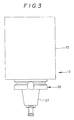
- a finger member 47 adapted to grasp the holder 28 shown in Fig. 3.
- the finger member in itself may be configured in a known manner.
- Operation of the linear drive means 44 causes the grasping arm 41 to be reciprocated between the extended position in which the finger member 47 grasps the pallet 2 at the detaching position P1 (Fig. 1) of the table 24 of the pallet storing device 8 and the contracted position which corresponds to the transfer position P2 (Fig. 1) where the pallet 2 is taken out of the pallet storing device 8 and transported.
- the center line B of the arm 31 which extends through the center of the pallet 2 to be grasped by the finger member 47 and in the direction of the displacement of the grasping arm 41 is so arranged as to cross with the rotary axis A.
- a bellow 48 is preferrably provided so as to prevent chips or dust from adhering to the ball screw 32 in the course of vertical movement of the arm 31.
- the extension and contraction stroke of the grasping arm 41 of the pallet exchanging arm device 9 relative to the respective pallet storing device 8 at the time of detaching the pallet may be constant.
- the pallet storing devices 8 each having a table 24 of an identical size the center of the pallet storing device will be located along the common circumference 50.
- a clamping device 3 or an index table for example for detaching a pallet 2 as the pallet exchanging section of the machine tool 1 may be disposed at an appropriate position along the circumference 49 on which the pallet detaching position P1 is to be located. In this instance, it is convenient if the extension and contraction stroke of the grasping arm 41 of the pallet exchanging device 9 is made same when the pallet for the pallet storing device 8 and the pallet for the machine tool 1 are exchanged.
- the pallet 2 with the workpiece 11 held at the upper side is attached to the pallet attaching section 26 of the pallet storing device 8 from the upper side
- the pallet 2 with the workpiece held on the lower surface is attached to the clamping device from the lower side. It is, accrodingly, necessary that the top and the bottom of the pallet 2 in the machine tool 1 must be turned over as against in the pallet storing device 8.
- the finger member 47 sould be of such a construction as it is rotatably supported on the grasping arm 41 around the axis B and should be rotatable over 180 degrees by means of the rotary device which is rotated by the rotary actuator such as an electric motor by way of a transmission device or by hydraulic power.
- a combination of the vertical motion of the arm 31, extension and contraction of the grasping arm 41, rotary motion of the finger member 47 relative to the grasping arm 41 and rotation of the arm 31 around the axis A enables pallets to be exchanged between the pallet storing device 8 and the machine tool 1.
- the pallets 2 are not directly attached to or detached from the clamping device 3 of the machine tool 1.
- the pallet exchanging section 10 is provided as an indipendent device from the machine tool 1 as shown in Fig. 1 whereby the pallets are exchanged intially between the pallet storing device 8 and the pallet exchanging section 10 and then the pallets 2 are exchanged between the pallet exchanging section and the machine tool 1.
- the independent pallet exchanging section 10 is provided with the pallet attaching section 26, provided at the reception position P3 and the exchanging arm 50 for transforming the pallet.
- the pallet attaching section 26' is so formed as to have the same construction as that of the pallet attaching section 26 of the pallet storing device 8 and the pallet 2 may be inserted and clamped.
- the pallet attaching section 26' of the pallet exchanging section 10 is so formed that the pallet 2 with the workpiece held at the lower side is inserted from the lower side and clamped in the same manner as the clamping device 3 of the machine tool 1. Accordingly, the pallet attaching section 26' of the pallet exchanging section 10 is configured to the manner of turning over relative to the pallet attaching section 26 of the pallet storing device 8.
- the exchanging arm 50 is rotatably supported in the substantially horizontal plane around the vertical rotary axis C and includes finger members 51 at the opposite ends.
- the finger member 51 is consisted of a finger member 51 having a well-known construction adapted to grasp or release pallets 2 by rotation around the rotary axis C of the exchanging arm 50. Rotation of the exchanging arm 50 allows the opposite finger member 51 to simultaneously grasp or release the pallets 2. As required, it is possible that the opposite finger members 51 separately allow the pallets to be grasped or released.
- a clockwise rotation of the arm causes the finger member 51 to simultaneously grasp the pallet at the reception position P3 and the pallet at the index table 3.
- the exchanging arm 40 graps the pallet 2, it will be lowered and extract the pallet 2 respectively from the pallet exchanging section 10 and the index table 3. Then it is rotated by 180 degrees either in the clockwise or anti-clockwise direction to exchange pallets.
- the exchanging arm 50 is raised to attach the exchanged pallets to the pallet exchanging section 10 and the index table 3. Subsequently, the exchanging arm 50 is rotated by 90 degrees in the anti-clockwise direction and waits for the next action at the position shown in Fig. 1.
- the pallet preparation device 11 that the pallet reception position P4 is located along the circle 49 along which the pallet attaching and detaching position P1 of the pallet storing device 8 is disposed.
- the workpiece on the pallet which has been machined is removed manually and a new workpiece to be machined is attached on an empty pallet. It is of course possible to automatically attach or detach workpieces to the pallets by means of a machine.
- the pallet attaching section 26 and the holding member are provided at a further preparation position P5 in addition to the reception position P4. In this way, pallet preparation work will be executed at another preparation position P5 and the prepared pallets will be set at the reception position P4 from the preparation position P5 manually or by means of a mechanical arm. In this way, the transport time spent by the exchanging arm device 12 may be prevented from being otherwise included in the preparation work.
- the arm 31 of the exchanging arm device 9 will assume vertical movement and rotation at the same time or sequentially and is caused to stop at the position opposed to the pallet attaching and detaching position P1 for the pallet storing device 8. Subsequently, the grasping arm 41 is extended so that the finger member 47 may grasp the holder 28 of the pallets 2. The arm 31 is caused to move upwards after it has grasped a pallet 2 and stop after it extracts a pallet 2 from the pallet attaching section 25. When the grasping arm 41 is contracted to be restored to the trasportation position P2, rotation and vertical downward movement of the arm 31 will cause the pallet to stop at the position corresponding to the reception position P3 of the pallet exchanging section 10 or the reception position P4 of the pallet preparation device 11.
- the grasping arm 41 is extended to place the pallet above the specified pallet mounting section 25 while the arm 41 is lowered to cause the pallet 2 to be attached to the pallet mouting section 25. After mounting, said grasping arm 41 is contracted to wait for the next action at the transfer position P2.
- the respective tables 24 will move the pallets 2 next to be treated to the detaching position P1 by taking advantage of the waiting time in which the exchanging arm device 9 is working.
Landscapes
- Engineering & Computer Science (AREA)
- Mechanical Engineering (AREA)
- Feeding Of Workpieces (AREA)
Applications Claiming Priority (2)
| Application Number | Priority Date | Filing Date | Title |
|---|---|---|---|
| JP134535/90 | 1990-05-24 | ||
| JP2134535A JPH078465B2 (ja) | 1990-05-24 | 1990-05-24 | 工作物反転機構付き工作機械 |
Publications (2)
| Publication Number | Publication Date |
|---|---|
| EP0484556A1 true EP0484556A1 (de) | 1992-05-13 |
| EP0484556A4 EP0484556A4 (en) | 1992-09-02 |
Family
ID=15130591
Family Applications (1)
| Application Number | Title | Priority Date | Filing Date |
|---|---|---|---|
| EP19910909719 Withdrawn EP0484556A4 (en) | 1990-05-24 | 1991-05-24 | Machine tool |
Country Status (3)
| Country | Link |
|---|---|
| EP (1) | EP0484556A4 (de) |
| JP (1) | JPH078465B2 (de) |
| WO (1) | WO1991017861A1 (de) |
Cited By (1)
| Publication number | Priority date | Publication date | Assignee | Title |
|---|---|---|---|---|
| EP0820835A1 (de) * | 1996-07-26 | 1998-01-28 | Grob-Werke GmbH & Co. KG | Bearbeitungszentrum |
Family Cites Families (6)
| Publication number | Priority date | Publication date | Assignee | Title |
|---|---|---|---|---|
| JPS5228789A (en) * | 1975-08-29 | 1977-03-03 | Takeo Itakura | Boring equipment for circular steel plate |
| SU880689A1 (ru) * | 1979-10-02 | 1981-11-15 | Ивановское Специальное Конструкторское Бюро Расточных Станков | Многооперационный станок |
| JPS5959334A (ja) * | 1982-09-27 | 1984-04-05 | Matsuura Kikai Seisakusho:Kk | 自動ワ−ク交換装置 |
| SU1166965A1 (ru) * | 1983-03-21 | 1985-07-15 | Одесское специальное конструкторское бюро специальных станков | Многоцелевой станок с ЧПУ |
| JPS61293701A (ja) * | 1985-06-18 | 1986-12-24 | Mori Seiki Seisakusho:Kk | Nc旋盤 |
| JPS6288536A (ja) * | 1985-10-15 | 1987-04-23 | Kitamura Kikai Kk | ワ−クステ−シヨン構造 |
-
1990
- 1990-05-24 JP JP2134535A patent/JPH078465B2/ja not_active Expired - Lifetime
-
1991
- 1991-05-24 EP EP19910909719 patent/EP0484556A4/en not_active Withdrawn
- 1991-05-24 WO PCT/JP1991/000702 patent/WO1991017861A1/ja not_active Ceased
Cited By (2)
| Publication number | Priority date | Publication date | Assignee | Title |
|---|---|---|---|---|
| EP0820835A1 (de) * | 1996-07-26 | 1998-01-28 | Grob-Werke GmbH & Co. KG | Bearbeitungszentrum |
| US5940948A (en) * | 1996-07-26 | 1999-08-24 | Grob-Werke Gmbh & Co. Kg | Machining center |
Also Published As
| Publication number | Publication date |
|---|---|
| WO1991017861A1 (fr) | 1991-11-28 |
| JPH0430932A (ja) | 1992-02-03 |
| EP0484556A4 (en) | 1992-09-02 |
| JPH078465B2 (ja) | 1995-02-01 |
Similar Documents
| Publication | Publication Date | Title |
|---|---|---|
| EP0462533B1 (de) | Palettenspeicher- und Palettenwechselvorrichtung für WZM und Drehbank mit automatisch auswechselbaren Paletten | |
| US3851380A (en) | Machine tool with tool module storage and changing means | |
| JPS63278738A (ja) | パレット交換装置 | |
| EP0364858A1 (de) | Paletten-Wechselvorrichtung | |
| US6416450B2 (en) | Machine tool with improved tool changer means | |
| EP1611994B1 (de) | Werkzeugmaschine mit Palettenwechselfunktion sowie Verfahren zum Palettenwechsel | |
| CN109333316B (zh) | 全自动化抛光生产线 | |
| EP0484556A1 (de) | Werkzeugmaschine | |
| CN111037348A (zh) | 一种工件交换装置和方法 | |
| CN117206914B (zh) | 盘毂类工件的车铣复合加工生产线 | |
| US5637069A (en) | Device for metal cutting | |
| JPS63109931A (ja) | 立形マシニングセンタ | |
| CN215469499U (zh) | 一种油压铰全自动生产线 | |
| CN211728475U (zh) | 一种工件交换装置 | |
| JPH03234437A (ja) | 工作機械用パレット交換装置 | |
| CN221603415U (zh) | 一种自动回牙机器人工作站 | |
| JPH03234436A (ja) | 工作機械用パレット貯留装置 | |
| JPS63256332A (ja) | パレツト交換装置 | |
| JPH0691573A (ja) | ロボットのハンドグリッパ及びグリッパの自動交換装置 | |
| JPH0120029B2 (de) | ||
| JP7282542B2 (ja) | 貯蔵装置及び移送システム | |
| JPS59219102A (ja) | 旋削機械のためのタ−レツトに支持した部品把持部 | |
| JPH0229458B2 (de) | ||
| JPH0966433A (ja) | ローディング・アンローディング装置 | |
| JPS63196344A (ja) | 工作機械 |
Legal Events
| Date | Code | Title | Description |
|---|---|---|---|
| PUAI | Public reference made under article 153(3) epc to a published international application that has entered the european phase |
Free format text: ORIGINAL CODE: 0009012 |
|
| 17P | Request for examination filed |
Effective date: 19920120 |
|
| AK | Designated contracting states |
Kind code of ref document: A1 Designated state(s): DE FR GB IT SE |
|
| A4 | Supplementary search report drawn up and despatched |
Effective date: 19920714 |
|
| AK | Designated contracting states |
Kind code of ref document: A4 Designated state(s): DE FR GB IT SE |
|
| 17Q | First examination report despatched |
Effective date: 19921118 |
|
| STAA | Information on the status of an ep patent application or granted ep patent |
Free format text: STATUS: THE APPLICATION IS DEEMED TO BE WITHDRAWN |
|
| 18D | Application deemed to be withdrawn |
Effective date: 19930805 |