EP0485963B1 - Kabelleiter-Biegeverfahren und Vorrichtung - Google Patents
Kabelleiter-Biegeverfahren und Vorrichtung Download PDFInfo
- Publication number
- EP0485963B1 EP0485963B1 EP91119291A EP91119291A EP0485963B1 EP 0485963 B1 EP0485963 B1 EP 0485963B1 EP 91119291 A EP91119291 A EP 91119291A EP 91119291 A EP91119291 A EP 91119291A EP 0485963 B1 EP0485963 B1 EP 0485963B1
- Authority
- EP
- European Patent Office
- Prior art keywords
- bending
- core wire
- electric cable
- cable
- clamping
- Prior art date
- Legal status (The legal status is an assumption and is not a legal conclusion. Google has not performed a legal analysis and makes no representation as to the accuracy of the status listed.)
- Expired - Lifetime
Links
- 238000005452 bending Methods 0.000 title claims description 41
- 238000000034 method Methods 0.000 title claims description 9
- 238000010438 heat treatment Methods 0.000 claims description 5
- 239000011248 coating agent Substances 0.000 claims description 3
- 238000000576 coating method Methods 0.000 claims description 3
- 239000012212 insulator Substances 0.000 description 3
- 239000004020 conductor Substances 0.000 description 2
- 239000012815 thermoplastic material Substances 0.000 description 2
- 239000004760 aramid Substances 0.000 description 1
- 229920006231 aramid fiber Polymers 0.000 description 1
- 238000010276 construction Methods 0.000 description 1
- 238000005485 electric heating Methods 0.000 description 1
- 239000004744 fabric Substances 0.000 description 1
- 239000007787 solid Substances 0.000 description 1
Images


Classifications
-
- H—ELECTRICITY
- H01—ELECTRIC ELEMENTS
- H01R—ELECTRICALLY-CONDUCTIVE CONNECTIONS; STRUCTURAL ASSOCIATIONS OF A PLURALITY OF MUTUALLY-INSULATED ELECTRICAL CONNECTING ELEMENTS; COUPLING DEVICES; CURRENT COLLECTORS
- H01R43/00—Apparatus or processes specially adapted for manufacturing, assembling, maintaining, or repairing of line connectors or current collectors or for joining electric conductors
- H01R43/28—Apparatus or processes specially adapted for manufacturing, assembling, maintaining, or repairing of line connectors or current collectors or for joining electric conductors for wire processing before connecting to contact members, not provided for in groups H01R43/02 - H01R43/26
-
- H—ELECTRICITY
- H01—ELECTRIC ELEMENTS
- H01R—ELECTRICALLY-CONDUCTIVE CONNECTIONS; STRUCTURAL ASSOCIATIONS OF A PLURALITY OF MUTUALLY-INSULATED ELECTRICAL CONNECTING ELEMENTS; COUPLING DEVICES; CURRENT COLLECTORS
- H01R43/00—Apparatus or processes specially adapted for manufacturing, assembling, maintaining, or repairing of line connectors or current collectors or for joining electric conductors
- H01R43/04—Apparatus or processes specially adapted for manufacturing, assembling, maintaining, or repairing of line connectors or current collectors or for joining electric conductors for forming connections by deformation, e.g. crimping tool
- H01R43/048—Crimping apparatus or processes
-
- Y—GENERAL TAGGING OF NEW TECHNOLOGICAL DEVELOPMENTS; GENERAL TAGGING OF CROSS-SECTIONAL TECHNOLOGIES SPANNING OVER SEVERAL SECTIONS OF THE IPC; TECHNICAL SUBJECTS COVERED BY FORMER USPC CROSS-REFERENCE ART COLLECTIONS [XRACs] AND DIGESTS
- Y10—TECHNICAL SUBJECTS COVERED BY FORMER USPC
- Y10T—TECHNICAL SUBJECTS COVERED BY FORMER US CLASSIFICATION
- Y10T29/00—Metal working
- Y10T29/49—Method of mechanical manufacture
- Y10T29/49002—Electrical device making
- Y10T29/49117—Conductor or circuit manufacturing
- Y10T29/49174—Assembling terminal to elongated conductor
- Y10T29/49181—Assembling terminal to elongated conductor by deforming
-
- Y—GENERAL TAGGING OF NEW TECHNOLOGICAL DEVELOPMENTS; GENERAL TAGGING OF CROSS-SECTIONAL TECHNOLOGIES SPANNING OVER SEVERAL SECTIONS OF THE IPC; TECHNICAL SUBJECTS COVERED BY FORMER USPC CROSS-REFERENCE ART COLLECTIONS [XRACs] AND DIGESTS
- Y10—TECHNICAL SUBJECTS COVERED BY FORMER USPC
- Y10T—TECHNICAL SUBJECTS COVERED BY FORMER US CLASSIFICATION
- Y10T29/00—Metal working
- Y10T29/49—Method of mechanical manufacture
- Y10T29/49002—Electrical device making
- Y10T29/49117—Conductor or circuit manufacturing
- Y10T29/49174—Assembling terminal to elongated conductor
- Y10T29/49181—Assembling terminal to elongated conductor by deforming
- Y10T29/49185—Assembling terminal to elongated conductor by deforming of terminal
- Y10T29/49192—Assembling terminal to elongated conductor by deforming of terminal with insulation removal
Definitions
- the present invention relates to a method and device for bending an exposed core wire of an electric cable for effecting a firm and tight connection with a terminal lug.
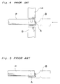
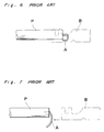
- US-A- 3,668,764 shows an example of the prior art method in which an exposed core wire of the electric cable is bent back along the cable surface, and then a terminal lug is applied around the end portion of the stripped end so that the exposed core wire is electrically held in contact with the terminal lug.
- a clamping unit 11 clamps the electric cable P which end portion is stripped of the coating member to expose a core wire A.
- the core wire A is brought under a punch 12.
- the downwardly bent core wire A is further bent back by the terminal lug B in such a direction that the exposed core wire A is bent in a U-shape, as shown in Fig. 4.
- a crimper 14 goes down to crimp the terminal lug B to locate the bent back core wire A between the terminal lug B and the insulating member of the cable P, as shown in Fig. 5.
- the bent portion of the core wire A bent according to the prior art as described above may returned by its resiliency, resulting in wire bending at the mid of the stripped wire portion in response to the backward movement of the lug B. In this case, a firm electric contact between the terminal lug B and the core wire A can not be ensured.
- the core wire A when the core wire A hangs down due to its resiliency, the core wire A may be undesirably cut by the edge of terminal lug B.
- the above problems are often observed with a wrapped type of electric cable P, such as shown in Fig. 8.
- the wrapped type electric cable P is formed by a tension member 1 made of aramid fibers.
- a core 2 of thermoplastic material is mounted on tension member 1 and a resistant wire (conductor) 3 is spirally wound around the core 2.
- An insulator 4 and sheath 5 are further mounted on the core 2 and the resistant wire 3.
- the object of the present invention is therefore to provide an electric cable bending method and an electric cable bending device which solves these problems.
- the present invention has been developed with a view to substantially solving the above described disadvantages and has for its essential object to provide an improved electric cable bending method and an improved electric cable bending device.
- a bending method for bending an exposed core wire of an electric cable comprises the steps of clamping the electric cable at a clamping position adjacent the exposed core wire, vertically bending the exposed core wire, while applying heat thereat, at an angle substantially perpendicularly to the axis of the electric cable, and horizontally bending the perpendicularly bent core wire, while applying heat thereat, at an angle to extend substantially parallel to the axis of the electric cable along the surface of the insulating member.
- the bending device BD has a generally U-shaped frame F including a horizontal base, a vertical stand and a top beam parallel to the horizontal base.
- a clamp unit 11 is provided at the front end and on the lower surface of the top beam for clamping the cable P.
- a support unit 20 is provided behind the clamping unit 11 for supporting the cable P against a vertical force, and a vertical hot press 16 is provided behind the support unit 20 for bending down an exposed core wire A of the cable P.
- a horizontal hot press 17 is provided behind the vertical hot press 16 and on the inner surface of the vertical stand for bending back the core wire A in U-shape.
- Clamping unit 11, support unit 20, vertical hot press 16, and reciprocating hot press 17 are coupled to and driven by a motor 15, a cylinder 21, a cylinder 18, and a cylinder 19, respectively.
- the cable P whose end portion is stripped is inserted so that the exposed core wire A of the cable P locates under the vertical hot press 16.
- the inserted position of the cable P is adjusted by strokes of a cable inserting jig (not shown).
- the clamping unit 11 is driven by the motor 15 via an appropriate gear box so as to clamp and hold the cable P at a clamping position.
- the vertical hot press unit 16 is stroked vertically and downwardly by the cylinder 18 to move from the position indicated by the solid line to the stroked position indicated by the dot-dash line.
- the support unit 20 is also vertically moved by the cylinder 21 from the initial position indicated by the solid to supporting position indicated by the dot-dash line to contact the cable P.
- the horizontal hot press unit 17 is horizontally moved by the cylinder 19 from the initial position indicated by the solid line to the extended position indicated by the dot-dash line to bend back the core wire A toward another end of the cable along the insulating member thereof.
- the hot presses 16 and 17 are heated by appropriate heating device such as an electric heating wires W1 and W2 incorporated therein.
- the electric cable P as shown in Fig. 8 is stripped of its insulating members to expose the core wire A therein. Stripping operation of the cable P is detailedly described in post-published EP-A-0487969. Then, the stripped cable P is inserted into the inserted position in which the cable P is clamped by the clamping unit 11 as described in the above. Clamping operation of the cable P are also detailedly described in EP-A-0487969.
- the vertical hot press 16 goes down as shown in Fig. 1, so that the core wire A is bent down by the hot press 16.
- the core wire A is bent perpendicularly.
- the support unit 20 goes down and contacts with the cable P at the insulating member thereof.
- the horizontal hot press 17 strokes forward.
- the bent core wire A is heated and further bent backward toward the other end of the cable P along with the surface of the insulating members 4 and 5 thereof. Since the support unit 20 supports the cable P against the pushing force generated by the hot press 17 during its movement to the extended position, the stripped portion, which is the core wire A, is permanently bent in U-shape as shown in Fig. 5.
- the cable P After bending of the core wire A by the bending device BD, the cable P is provided with a terminal lug B in the same manner as that described above in connection with Figs. 2, 3, and 4.
- the permanently bent core wire A will not return to the straight condition.
- the electrical connection between the core wire A and the terminal lug B can be accomplished firmly with a high reliability.
Landscapes
- Engineering & Computer Science (AREA)
- Manufacturing & Machinery (AREA)
- Manufacturing Of Electrical Connectors (AREA)
- Processing Of Terminals (AREA)
- Wire Processing (AREA)
Claims (4)
- Biegeverfahren zum Biegen einer freiliegenden Leiterader (A) eines elektrischen Kabels (P), wobei das Verfahren die Schritte aufweist:
Einspannen des elektrischen Kabels (P) in einer Einspannposition nahe der freiliegenden Leiterader (A);
vertikales Biegen der freiliegenden Leiterader (A) unter Zuführung von Wärme zu einem Winkel, der im wesentlichen senkrecht zur Achse des elektrischen Kabels (P) ist; und
horizontales Biegen der senkrecht gebogenen Leiterader (A) unter Zuführung von Wärme zu einem Winkel, der sich im wesentlichen parallel zur Achse des elektrischen Kabels (P) entlang der Oberfläche des Isolierteils (4, 5) erstreckt. - Biegeverfahren nach Anspruch 1 mit dem Schritt zum Abstützen des elektrischen Kabels (P) gegen eine zu diesem senkrechte Schubkraft, die während des horizontalen Biegeschrittes wirkt.
- Biegevorrichtung für elektrische Kabel (BD) zum Biegen eines freiliegenden Abschnitts einer Leiterader (A) eines elektrischen Kabels (P), wobei die Vorrichtung aufweist:
eine Rahmenkonstruktion (F);
eine Einspanneinrichtung (11, 15), die an der Rahmenkonstruktion (F) angeordnet ist, zum Einspannen des elektrischen Kabels (P) in einer Einspannposition nahe der freiliegenden Leiterader (A);
eine erste Biegeeinrichtung (16, 18) mit einer ersten Heizeinrichtung (W1), wobei die erste Biegeeinrichtung an der Rahmenkonstruktion (F) angeordnet ist, zum Erwärmen und Biegen der freiliegenden Leiterader (A) im wesentlichen senkrecht zur Achse des elektrischen Kabels (P) , wenn die erste Biegeeinrichtung (16, 18) sich vertikal aus einer ersten Position in eine zweite Position verschiebt;
eine zweite Biegeeinrichtung (17, 19) mit einer zweiten Heizeinrichtung (W2), wobei die zweite Biegeeinrichtung an der Rahmenkonstruktion (F) angeordnet ist, zum Erwärmen und Zurückbiegen der senkrecht gebogenen Leiterader (A) im wesentlichen parallel zur Achse des elektrischen Kabels (P) entlang der Oberfläche des Beschichtungsteils (4, 5). - Biegevorrichtung für elektrische Kabel (BD) nach Anspruch 3, ferner mit einer Halteeinrichtung (20, 21), die an der Rahmenkonstruktion (F) angeordnet ist, zum Abstützen des elektrischen Kabels (P) in einer Position nahe dem freiliegenden Abschnitt der Leiterader (A) gegen eine Schubkraft, die von der zweiten Biegeeinrichtung während ihrer horizontalen Hin- und Herbewegung erzeugt wird.
Applications Claiming Priority (2)
| Application Number | Priority Date | Filing Date | Title |
|---|---|---|---|
| JP308242/90 | 1990-11-13 | ||
| JP2308242A JP2633722B2 (ja) | 1990-11-13 | 1990-11-13 | 電線の端末心線折り曲げ装置 |
Publications (2)
| Publication Number | Publication Date |
|---|---|
| EP0485963A1 EP0485963A1 (de) | 1992-05-20 |
| EP0485963B1 true EP0485963B1 (de) | 1995-02-15 |
Family
ID=17978653
Family Applications (1)
| Application Number | Title | Priority Date | Filing Date |
|---|---|---|---|
| EP91119291A Expired - Lifetime EP0485963B1 (de) | 1990-11-13 | 1991-11-12 | Kabelleiter-Biegeverfahren und Vorrichtung |
Country Status (4)
| Country | Link |
|---|---|
| US (1) | US5186036A (de) |
| EP (1) | EP0485963B1 (de) |
| JP (1) | JP2633722B2 (de) |
| DE (1) | DE69107413T2 (de) |
Families Citing this family (5)
| Publication number | Priority date | Publication date | Assignee | Title |
|---|---|---|---|---|
| US6094957A (en) * | 1999-06-30 | 2000-08-01 | Masunaga Optical Mfg. Co., Ltd. | Method for bending difficult-to-work metallic wire and method for shaping coil section thereof |
| JP3185208B2 (ja) * | 1999-08-24 | 2001-07-09 | 住友電気工業株式会社 | 電線加工品の製造方法、その製造装置、及び電線加工品 |
| EP2006963B1 (de) | 2007-05-16 | 2009-07-29 | Delphi Technologies, Inc. | Befestigungsverfahren für einen Kabelschuh und Kabelbiegevorrichtung |
| CN108832464A (zh) * | 2018-06-06 | 2018-11-16 | 潘真清 | 一种电线折弯钳 |
| CN118039228B (zh) * | 2024-01-31 | 2025-06-06 | 芜湖佳宏新材料股份有限公司 | 一种绕丝结构的发热电缆及其绕丝设备 |
Family Cites Families (9)
| Publication number | Priority date | Publication date | Assignee | Title |
|---|---|---|---|---|
| US2473919A (en) * | 1947-08-14 | 1949-06-21 | Gen Electric | Method and apparatus for assembling incandescent lamp mounts |
| US2472778A (en) * | 1948-05-22 | 1949-06-07 | Sylvania Electric Prod | Coil clamping method and apparatus |
| AT216303B (de) * | 1958-11-26 | 1961-07-25 | Wacker Chemie Gmbh | Verfahren zum Biegen und Deformieren von kristallinen, spröden Stoffen |
| US3668764A (en) * | 1970-12-24 | 1972-06-13 | Artos Engineering Co | Automatic terminal applicator for insulated non-metallic ignition type wires |
| JPS5227833A (en) * | 1975-08-23 | 1977-03-02 | Howa Machinery Ltd | Controlling apparatus for high speed rotary drive of takeeup cheese in automatic yarn splicing machine |
| US4288917A (en) * | 1978-06-26 | 1981-09-15 | Akzona Incorporated | Method of forming connector-cable with crimped electrical terminations |
| FR2507827B1 (fr) * | 1981-06-11 | 1985-10-04 | Electricfil Ind Sarl | Embout coude de raccordement electrique |
| JPH0663885B2 (ja) * | 1988-09-19 | 1994-08-22 | 工業技術院長 | 分布型圧覚センサの製造方法 |
| JP2741221B2 (ja) * | 1988-11-15 | 1998-04-15 | 臼井国際産業株式会社 | 二重管の製造方法 |
-
1990
- 1990-11-13 JP JP2308242A patent/JP2633722B2/ja not_active Expired - Lifetime
-
1991
- 1991-11-08 US US07/789,609 patent/US5186036A/en not_active Expired - Lifetime
- 1991-11-12 EP EP91119291A patent/EP0485963B1/de not_active Expired - Lifetime
- 1991-11-12 DE DE69107413T patent/DE69107413T2/de not_active Expired - Fee Related
Also Published As
| Publication number | Publication date |
|---|---|
| EP0485963A1 (de) | 1992-05-20 |
| DE69107413D1 (de) | 1995-03-23 |
| JPH04179083A (ja) | 1992-06-25 |
| DE69107413T2 (de) | 1995-06-08 |
| JP2633722B2 (ja) | 1997-07-23 |
| US5186036A (en) | 1993-02-16 |
Similar Documents
| Publication | Publication Date | Title |
|---|---|---|
| EP0485964A2 (de) | Entmantelungsverfahren elektrischer Kabel und Vorrichtung zum Auflockern elektrischer Kabel | |
| US4966565A (en) | Crimp-style terminal and method of connecting crimp-style terminal and electric cable together | |
| US5660742A (en) | Insulated wire termination, method, and machine | |
| CN110021867B (zh) | 多芯电缆制造装置和多芯电缆制造方法 | |
| EP0719462B1 (de) | Koaxialverbinder | |
| GB2070469A (en) | Electrical interconnection | |
| EP0485963B1 (de) | Kabelleiter-Biegeverfahren und Vorrichtung | |
| US4492344A (en) | Fixture for a wire in a wire-winding device for an electric machine | |
| CA1159525A (en) | Cable clamping device with a movable pressure member | |
| US4019236A (en) | Crimping press clamp for electrical connectors | |
| US5342996A (en) | Inter-connecting terminal | |
| EP1039591B1 (de) | Pressschweissgerät und Pressschweissverfahren | |
| US3529342A (en) | Apparatus for joining wires | |
| US3986256A (en) | Adapter for positioning multi-conductor cable and electrical connector | |
| US3864009A (en) | Connector and method | |
| JPH05242931A (ja) | 同軸コネクタ | |
| JPH10149843A (ja) | 溶接端子 | |
| EP0570832A1 (de) | Verbindergehäuseanordnung für einzelne Drähte | |
| US20060134988A1 (en) | Cable connector and method for assembling such a connector | |
| CN119481874B (zh) | 一种线束端子压接方法及其压接设备 | |
| US11677167B2 (en) | Electric wire with terminal and terminal crimping device | |
| JPH06150987A (ja) | 圧接端子および該端子を用いた被覆電線の接続方法 | |
| EP0442686A1 (de) | Elektrische Sammelschiene mit Erdungsverfahren und -vorrichtung | |
| JP2024131158A (ja) | 端子圧着装置及び端子の圧着方法 | |
| US3186078A (en) | Apparatus for making electrical connections |
Legal Events
| Date | Code | Title | Description |
|---|---|---|---|
| PUAI | Public reference made under article 153(3) epc to a published international application that has entered the european phase |
Free format text: ORIGINAL CODE: 0009012 |
|
| AK | Designated contracting states |
Kind code of ref document: A1 Designated state(s): DE FR GB |
|
| 17P | Request for examination filed |
Effective date: 19920818 |
|
| 17Q | First examination report despatched |
Effective date: 19940307 |
|
| GRAA | (expected) grant |
Free format text: ORIGINAL CODE: 0009210 |
|
| AK | Designated contracting states |
Kind code of ref document: B1 Designated state(s): DE FR GB |
|
| REF | Corresponds to: |
Ref document number: 69107413 Country of ref document: DE Date of ref document: 19950323 |
|
| ET | Fr: translation filed | ||
| PLBE | No opposition filed within time limit |
Free format text: ORIGINAL CODE: 0009261 |
|
| STAA | Information on the status of an ep patent application or granted ep patent |
Free format text: STATUS: NO OPPOSITION FILED WITHIN TIME LIMIT |
|
| 26N | No opposition filed | ||
| PGFP | Annual fee paid to national office [announced via postgrant information from national office to epo] |
Ref country code: GB Payment date: 19971031 Year of fee payment: 7 |
|
| PGFP | Annual fee paid to national office [announced via postgrant information from national office to epo] |
Ref country code: FR Payment date: 19971128 Year of fee payment: 7 |
|
| PGFP | Annual fee paid to national office [announced via postgrant information from national office to epo] |
Ref country code: DE Payment date: 19980130 Year of fee payment: 7 |
|
| PG25 | Lapsed in a contracting state [announced via postgrant information from national office to epo] |
Ref country code: GB Free format text: LAPSE BECAUSE OF NON-PAYMENT OF DUE FEES Effective date: 19981112 |
|
| GBPC | Gb: european patent ceased through non-payment of renewal fee |
Effective date: 19981112 |
|
| PG25 | Lapsed in a contracting state [announced via postgrant information from national office to epo] |
Ref country code: FR Free format text: LAPSE BECAUSE OF NON-PAYMENT OF DUE FEES Effective date: 19990730 |
|
| REG | Reference to a national code |
Ref country code: FR Ref legal event code: ST |
|
| PG25 | Lapsed in a contracting state [announced via postgrant information from national office to epo] |
Ref country code: DE Free format text: LAPSE BECAUSE OF NON-PAYMENT OF DUE FEES Effective date: 19990901 |