EP0486726A1 - Pompe à anneau liquide - Google Patents
Pompe à anneau liquide Download PDFInfo
- Publication number
- EP0486726A1 EP0486726A1 EP90122405A EP90122405A EP0486726A1 EP 0486726 A1 EP0486726 A1 EP 0486726A1 EP 90122405 A EP90122405 A EP 90122405A EP 90122405 A EP90122405 A EP 90122405A EP 0486726 A1 EP0486726 A1 EP 0486726A1
- Authority
- EP
- European Patent Office
- Prior art keywords
- ring pump
- liquid ring
- separator
- condensate
- liquid
- Prior art date
- Legal status (The legal status is an assumption and is not a legal conclusion. Google has not performed a legal analysis and makes no representation as to the accuracy of the status listed.)
- Granted
Links
- 239000007788 liquid Substances 0.000 title claims abstract description 57
- 238000001816 cooling Methods 0.000 claims abstract description 16
- 230000007423 decrease Effects 0.000 claims abstract description 3
- 239000012530 fluid Substances 0.000 claims description 23
- 230000001105 regulatory effect Effects 0.000 claims description 4
- 239000007789 gas Substances 0.000 description 13
- XLYOFNOQVPJJNP-UHFFFAOYSA-N water Chemical compound O XLYOFNOQVPJJNP-UHFFFAOYSA-N 0.000 description 9
- 230000033228 biological regulation Effects 0.000 description 3
- 230000006835 compression Effects 0.000 description 3
- 238000007906 compression Methods 0.000 description 3
- 238000005086 pumping Methods 0.000 description 3
- 229920006395 saturated elastomer Polymers 0.000 description 2
- 238000009834 vaporization Methods 0.000 description 2
- 230000008016 vaporization Effects 0.000 description 2
- 238000013459 approach Methods 0.000 description 1
- 238000007664 blowing Methods 0.000 description 1
- 238000009833 condensation Methods 0.000 description 1
- 230000005494 condensation Effects 0.000 description 1
- 230000001419 dependent effect Effects 0.000 description 1
- 238000001704 evaporation Methods 0.000 description 1
- 230000008020 evaporation Effects 0.000 description 1
- 238000011084 recovery Methods 0.000 description 1
Images
Classifications
-
- F—MECHANICAL ENGINEERING; LIGHTING; HEATING; WEAPONS; BLASTING
- F04—POSITIVE - DISPLACEMENT MACHINES FOR LIQUIDS; PUMPS FOR LIQUIDS OR ELASTIC FLUIDS
- F04C—ROTARY-PISTON, OR OSCILLATING-PISTON, POSITIVE-DISPLACEMENT MACHINES FOR LIQUIDS; ROTARY-PISTON, OR OSCILLATING-PISTON, POSITIVE-DISPLACEMENT PUMPS
- F04C19/00—Rotary-piston pumps with fluid ring or the like, specially adapted for elastic fluids
- F04C19/004—Details concerning the operating liquid, e.g. nature, separation, cooling, cleaning, control of the supply
-
- F—MECHANICAL ENGINEERING; LIGHTING; HEATING; WEAPONS; BLASTING
- F04—POSITIVE - DISPLACEMENT MACHINES FOR LIQUIDS; PUMPS FOR LIQUIDS OR ELASTIC FLUIDS
- F04C—ROTARY-PISTON, OR OSCILLATING-PISTON, POSITIVE-DISPLACEMENT MACHINES FOR LIQUIDS; ROTARY-PISTON, OR OSCILLATING-PISTON, POSITIVE-DISPLACEMENT PUMPS
- F04C29/00—Component parts, details or accessories of pumps or pumping installations, not provided for in groups F04C18/00 - F04C28/00
- F04C29/04—Heating; Cooling; Heat insulation
- F04C29/042—Heating; Cooling; Heat insulation by injecting a fluid
Definitions
- the invention relates to a liquid ring pump according to the preamble of claim 1 and claim 4.
- liquid ring pump In the liquid ring pump, a liquid ring of operating liquid circulates through an impeller in a housing.
- the liquid ring stands out on the suction side of the impeller hub so that the gas to be pumped can enter. On the pressure side, the liquid ring approaches the impeller hub again, whereby the now compressed delivery gas is pushed out.
- the liquid ring pump works with a downstream separator for the recovery of operating fluid.
- the return line of the separator is optionally passed through a heat exchanger to cool down the operating fluid.
- Liquid ring pumps are particularly suitable for the oil-free compression of dry gases that are partially or completely saturated with water vapor.
- the pumping speed and the suction pressure change with the temperature of the operating liquid, since the vapor pressure is temperature-dependent.
- Usual operating characteristics are recorded for the suction of air with 100% relative humidity and a temperature of 20 ° C as well as for water as operating liquid at a temperature of 15 ° C.
- the operating fluid also has another function, namely to dissipate the compression heat and, if necessary, to seal gaps between the impeller and control disks and, if necessary, also to cool internal parts of a shaft seal.
- the operating fluid that is pushed out can be separated from the conveying gas in a downstream separator.
- the invention has for its object to develop a liquid ring pump that works more economically and less sensitive to changes in temperature and relative humidity of the conveying gas.
- the operating liquid present in the exhaust air is recovered by a heat exchanger arranged in the exhaust air line of the separator.
- the cooling capacity of the heat exchanger is regulated as a function of a level sensor on the condensate of the separator in such a way that the cooling capacity increases as the condensate level falls and the cooling capacity decreases as the condensate level increases.
- liquid ring pump If you want to make compromises for special reasons, you can train the liquid ring pump according to claim 2 and arrange a drain valve and an inlet valve in the return line between the separator and the heat exchanger. So that can the liquid ring pump also work in a superimposed mode with operating liquid to be supplied and drained.
- a liquid ring pump according to claim 3 offers, due to an air cooler connected to the return line of the separator, a further improved cooling capacity and thus a further improved pumping speed. All operating fluid in the circuit is cooled by the air cooler. The operating fluid is recovered from the exhaust air via the heat exchanger located in the exhaust air line.
- the liquid ring pump by blowing air into the separator, more air is available which can become saturated with the operating liquid, preferably water.
- the heat of vaporization necessary to saturate the air with the operating fluid is extracted from the operating fluid, the operating fluid is thereby cooled.
- the loss of operating fluid that occurs must be replaced. This can be done via supply lines, e.g. are arranged according to claims 8 to 10.
- Another possibility is the condensation of the operating fluid via a heat exchanger connected to the exhaust air line.
- a gas ring compressor or fan which presses air into the separator, can also be arranged in liquid ring pumps in which heat exchangers are arranged in the exhaust air line and, if appropriate, in the return line as well.
- a liquid ring pump is then obtained according to claim 5.
- the gas ring compressor or the fan can be arranged in such a way that the air is introduced either through the condensate or above the condensate into the separator.
- Both the regulation of the supply of operating fluid and the regulation of the cooling capacity of the heat exchanger should preferably be carried out via a level sensor which e.g. can be formed according to claim 13 or 14.
- a level sensor which e.g. can be formed according to claim 13 or 14.
- Advantageous exemplary embodiments are specified in claims 11 and 12 for regulating the supply of operating fluid.
- liquid ring pump In a liquid ring pump according to claim 15, the pumping speed and the achievable vacuum is further improved. A liquid ring pump designed in this way is thus even more economical.
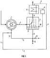
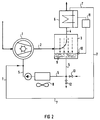
- 1 denotes a liquid ring pump, which is followed by a separator 3 via a connecting line 2.
- the separator 3 has an exhaust air line 4 which opens into the atmosphere. Furthermore, the separator 3 is connected to the liquid ring pump 1 via a return line 5.
- a heat exchanger 6 is arranged in the exhaust air line 4 and is connected to the return line 5 via a pipe 7.
- the separator 3, together with the heat exchanger 6, serves to recover operating liquid which, after compression of the gas to be conveyed, is partially pressed out of the liquid ring pump 1.
- the recovered operating fluid from the separator 3 is returned to the liquid ring pump 1 via the return line 5 and from the heat exchanger 6 via the pipeline 7.
- the level of the condensate 9 formed by the operating liquid in the separator 3 is detected by a level sensor 10, which preferably comprises a Peltier element.
- the level sensor 10 is functionally part of a controller 11.
- the controller 11 therefore regulates the cooling capacity of the heat exchanger 6 as a function of the level of the condensate 9.
- the regulation takes place in such a way that the cooling capacity is increased when the condensate level drops and the cooling capacity is reduced when the condensate level increases .
- the condensate level drops the condensate gain increases and, when the condensate level is high, discharge through evaporation. Water is usually used as the operating fluid.
- an amount of heat exchanger 6 is required Handling operating fluid in the order of 450 kg per hour.
- a drain valve 12 and / or an inlet valve 13 can be provided in the return line 5 between separator 3 and air cooler 8.
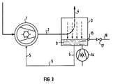
- a gas ring compressor 14 is arranged on the separator 3.
- the gas ring compressor 14 blows air from the atmosphere into the separator 3.
- the air is introduced through the condensate 9 into the separator 3. This results in a particularly high degree of saturation of the air introduced.
- the heat of vaporization required to saturate the air with water is extracted from the water, which is thereby cooled.
- the water loss which occurs in this case leads to a lowering of the condensate 9.
- the lowering of the condensate 9 is advantageously detected by a level sensor 15 which is designed as a float switch and automatically connects a water-carrying supply line 16.
- the connection of the supply line 16 can in turn take place via an inlet valve 17.
Landscapes
- Engineering & Computer Science (AREA)
- Mechanical Engineering (AREA)
- General Engineering & Computer Science (AREA)
- Structures Of Non-Positive Displacement Pumps (AREA)
- Applications Or Details Of Rotary Compressors (AREA)
Priority Applications (2)
| Application Number | Priority Date | Filing Date | Title |
|---|---|---|---|
| DE59006448T DE59006448D1 (de) | 1990-11-23 | 1990-11-23 | Flüssigkeitsringpumpe. |
| EP19900122405 EP0486726B1 (fr) | 1990-11-23 | 1990-11-23 | Pompe à anneau liquide |
Applications Claiming Priority (1)
| Application Number | Priority Date | Filing Date | Title |
|---|---|---|---|
| EP19900122405 EP0486726B1 (fr) | 1990-11-23 | 1990-11-23 | Pompe à anneau liquide |
Publications (2)
| Publication Number | Publication Date |
|---|---|
| EP0486726A1 true EP0486726A1 (fr) | 1992-05-27 |
| EP0486726B1 EP0486726B1 (fr) | 1994-07-13 |
Family
ID=8204745
Family Applications (1)
| Application Number | Title | Priority Date | Filing Date |
|---|---|---|---|
| EP19900122405 Expired - Lifetime EP0486726B1 (fr) | 1990-11-23 | 1990-11-23 | Pompe à anneau liquide |
Country Status (2)
| Country | Link |
|---|---|
| EP (1) | EP0486726B1 (fr) |
| DE (1) | DE59006448D1 (fr) |
Cited By (10)
| Publication number | Priority date | Publication date | Assignee | Title |
|---|---|---|---|---|
| EP0638723A1 (fr) * | 1993-08-11 | 1995-02-15 | Siemens Aktiengesellschaft | Compresseur mécanique |
| EP0641583A1 (fr) * | 1993-09-01 | 1995-03-08 | Alcatel Cit | Installation pour l'épuration en continu d'un solvant |
| US5618164A (en) * | 1994-12-06 | 1997-04-08 | Siemens Aktiengesellschaft | Liquid ring compressor with plural after-cooler elements |
| DE29714851U1 (de) * | 1997-08-19 | 1997-10-23 | Siemens AG, 80333 München | Flüssigkeitsringpumpenaggregat |
| EP1270832A1 (fr) * | 2001-06-29 | 2003-01-02 | Evac International Oy | Système d'évacuation sous vide d'eaux usées |
| CN101435426B (zh) * | 2007-11-12 | 2013-05-29 | 英格索尔-兰德公司 | 带有流量控制传感器的压缩机 |
| CN105822577A (zh) * | 2015-01-06 | 2016-08-03 | 中国石化工程建设有限公司 | 一种液环泵/压缩机系统和防止过载的方法 |
| CN108223375A (zh) * | 2017-11-23 | 2018-06-29 | 中材节能股份有限公司 | 一种一体化液环抽真空装置 |
| CN112344215A (zh) * | 2020-09-18 | 2021-02-09 | 南通新金丰皮革机械有限公司 | 一种皮革用真空系统液体供料装置 |
| CN116641890A (zh) * | 2023-06-14 | 2023-08-25 | 广东肯富来泵业股份有限公司 | 可防冻防高温及结晶物的液环泵系统及其控制方法 |
Families Citing this family (2)
| Publication number | Priority date | Publication date | Assignee | Title |
|---|---|---|---|---|
| US6190432B1 (en) | 1999-02-26 | 2001-02-20 | Donaldson Company, Inc. | Filter arrangement; sealing system; and methods |
| US20180245594A1 (en) * | 2017-02-24 | 2018-08-30 | Gardner Denver Nash Llc | Pump system including a controller |
Citations (4)
| Publication number | Priority date | Publication date | Assignee | Title |
|---|---|---|---|---|
| US3785755A (en) * | 1971-11-22 | 1974-01-15 | Rogers Machinery Co Inc | Air compressor system |
| DE2511334A1 (de) * | 1975-03-14 | 1976-09-23 | Siemens Ag | Geraet zum verdichten von gas oder gasgemischen |
| US4260335A (en) * | 1976-12-15 | 1981-04-07 | Air Industrie | Process for the compression of steam and thermal circuits for its implementation |
| FR2553500A1 (fr) * | 1983-10-14 | 1985-04-19 | Sihi Pompes | Procede et dispositif de recuperation de vapeurs d'hydrocarbures |
-
1990
- 1990-11-23 EP EP19900122405 patent/EP0486726B1/fr not_active Expired - Lifetime
- 1990-11-23 DE DE59006448T patent/DE59006448D1/de not_active Expired - Fee Related
Patent Citations (4)
| Publication number | Priority date | Publication date | Assignee | Title |
|---|---|---|---|---|
| US3785755A (en) * | 1971-11-22 | 1974-01-15 | Rogers Machinery Co Inc | Air compressor system |
| DE2511334A1 (de) * | 1975-03-14 | 1976-09-23 | Siemens Ag | Geraet zum verdichten von gas oder gasgemischen |
| US4260335A (en) * | 1976-12-15 | 1981-04-07 | Air Industrie | Process for the compression of steam and thermal circuits for its implementation |
| FR2553500A1 (fr) * | 1983-10-14 | 1985-04-19 | Sihi Pompes | Procede et dispositif de recuperation de vapeurs d'hydrocarbures |
Non-Patent Citations (1)
| Title |
|---|
| PATENT ABSTRACTS OF JAPAN vol. 12, no. 116 (M-684)(2963) 13 April 1988, & JP-A-62 243981 (HITACHI LTD) 24 Oktober 1987, * |
Cited By (13)
| Publication number | Priority date | Publication date | Assignee | Title |
|---|---|---|---|---|
| EP0638723A1 (fr) * | 1993-08-11 | 1995-02-15 | Siemens Aktiengesellschaft | Compresseur mécanique |
| US5511953A (en) * | 1993-08-11 | 1996-04-30 | Siemens Aktiengesellschaft | Mechanical compressor system |
| EP0641583A1 (fr) * | 1993-09-01 | 1995-03-08 | Alcatel Cit | Installation pour l'épuration en continu d'un solvant |
| FR2709428A1 (fr) * | 1993-09-01 | 1995-03-10 | Cit Alcatel | Installation pour l'épuration en continu d'un solvant. |
| US5618164A (en) * | 1994-12-06 | 1997-04-08 | Siemens Aktiengesellschaft | Liquid ring compressor with plural after-cooler elements |
| DE29714851U1 (de) * | 1997-08-19 | 1997-10-23 | Siemens AG, 80333 München | Flüssigkeitsringpumpenaggregat |
| EP1270832A1 (fr) * | 2001-06-29 | 2003-01-02 | Evac International Oy | Système d'évacuation sous vide d'eaux usées |
| CN101435426B (zh) * | 2007-11-12 | 2013-05-29 | 英格索尔-兰德公司 | 带有流量控制传感器的压缩机 |
| CN105822577A (zh) * | 2015-01-06 | 2016-08-03 | 中国石化工程建设有限公司 | 一种液环泵/压缩机系统和防止过载的方法 |
| CN105822577B (zh) * | 2015-01-06 | 2018-01-09 | 中国石化工程建设有限公司 | 一种液环泵/压缩机系统和防止过载的方法 |
| CN108223375A (zh) * | 2017-11-23 | 2018-06-29 | 中材节能股份有限公司 | 一种一体化液环抽真空装置 |
| CN112344215A (zh) * | 2020-09-18 | 2021-02-09 | 南通新金丰皮革机械有限公司 | 一种皮革用真空系统液体供料装置 |
| CN116641890A (zh) * | 2023-06-14 | 2023-08-25 | 广东肯富来泵业股份有限公司 | 可防冻防高温及结晶物的液环泵系统及其控制方法 |
Also Published As
| Publication number | Publication date |
|---|---|
| EP0486726B1 (fr) | 1994-07-13 |
| DE59006448D1 (de) | 1994-08-18 |
Similar Documents
| Publication | Publication Date | Title |
|---|---|---|
| EP0486726B1 (fr) | Pompe à anneau liquide | |
| CH695869A5 (de) | Mehrstufiger, zwischen Last- und Leerlaufbetrieb umschaltbarer Verdichter. | |
| DE69205534T2 (de) | Schmierölrückgewinnung in eine Kreiselverdichterkühlanlage. | |
| EP0088226A2 (fr) | Procédé d'actionnement d'une pompe à vide à anneau liquide | |
| DE69612891T2 (de) | Kältekreislauf mit Entspannung in einer Turbine mit einem Turbinenbypass | |
| DE2231945A1 (de) | Dampfkondensationsanlage mit mindestens zwei wassergekuehlten und an luftseitig in reihe geschalteten kuehlelementen angeschlossenen waermetauschern | |
| DE3026203A1 (de) | Oelgekuehlter kompressor | |
| DE10048439A1 (de) | Dampfturbinenanlage und Verfahren zum Betreiben einer Dampfturbinenanlage | |
| EP0638723B1 (fr) | Installation de compression mécanique | |
| DE2061917C3 (de) | Kühleinrichtung mit einem Durchflußsteuerventil zwischen Kondensator und Dosiervorrichtung | |
| CH646774A5 (de) | Waermepumpe. | |
| EP0437637A1 (fr) | Pompe à anneau liquide | |
| DE968232C (de) | Fluessigkeitsring-Vakuumpumpe mit vorgeschaltetem Strahlsauger | |
| DE3511421C2 (fr) | ||
| WO2003083307A1 (fr) | Systeme de pompage, procede de fonctionnement d'un systeme de pompage et utilisation dudit systeme dans une installation de turbine a vapeur | |
| EP0802329A2 (fr) | Dispositif pour l'aération d'un réservoir | |
| DE2503873B2 (de) | Flüssigkeitsringpumpenaggregat | |
| DE1926395A1 (de) | Entlueftungsgeraet fuer Abdampfkondensatoren von Dampfturbinen | |
| DE102016221255A1 (de) | Abwärmenutzungskreislauf, insbesondere für ein Kraftfahrzeug | |
| DE2113038A1 (de) | Mess- und Regelanordnung zum kondensatfreien Betrieb von Gasverdichtern | |
| DE1428047A1 (de) | Verfahren und Vorrichtung zum kondensationsfreien Betrieb von mehrstufigen Turboverdichtern mit Zwischenkuehlung | |
| DE10046902B4 (de) | Pumpenanlage und Verfahren zum Pumpen eines Gases | |
| DE102023131330A1 (de) | System zur Gewinnung von Kohlenstoffdioxid aus einem Gasgemisch | |
| DE10019718A1 (de) | Verfahren zum Betreiben einer Pumpvorrichtung und Pumpvorrichtung | |
| DE1428186A1 (de) | OElabscheide-Vorrichtung fuer oelgekuehlte Gasverdichter |
Legal Events
| Date | Code | Title | Description |
|---|---|---|---|
| PUAI | Public reference made under article 153(3) epc to a published international application that has entered the european phase |
Free format text: ORIGINAL CODE: 0009012 |
|
| 17P | Request for examination filed |
Effective date: 19901205 |
|
| AK | Designated contracting states |
Kind code of ref document: A1 Designated state(s): BE DE FR IT NL |
|
| 17Q | First examination report despatched |
Effective date: 19931019 |
|
| GRAA | (expected) grant |
Free format text: ORIGINAL CODE: 0009210 |
|
| AK | Designated contracting states |
Kind code of ref document: B1 Designated state(s): BE DE FR IT NL |
|
| REF | Corresponds to: |
Ref document number: 59006448 Country of ref document: DE Date of ref document: 19940818 |
|
| ITF | It: translation for a ep patent filed | ||
| ET | Fr: translation filed | ||
| PLBE | No opposition filed within time limit |
Free format text: ORIGINAL CODE: 0009261 |
|
| STAA | Information on the status of an ep patent application or granted ep patent |
Free format text: STATUS: NO OPPOSITION FILED WITHIN TIME LIMIT |
|
| 26N | No opposition filed | ||
| PGFP | Annual fee paid to national office [announced via postgrant information from national office to epo] |
Ref country code: BE Payment date: 19961114 Year of fee payment: 7 |
|
| PGFP | Annual fee paid to national office [announced via postgrant information from national office to epo] |
Ref country code: NL Payment date: 19961118 Year of fee payment: 7 |
|
| PGFP | Annual fee paid to national office [announced via postgrant information from national office to epo] |
Ref country code: FR Payment date: 19961129 Year of fee payment: 7 |
|
| PGFP | Annual fee paid to national office [announced via postgrant information from national office to epo] |
Ref country code: DE Payment date: 19970121 Year of fee payment: 7 |
|
| PG25 | Lapsed in a contracting state [announced via postgrant information from national office to epo] |
Ref country code: FR Free format text: THE PATENT HAS BEEN ANNULLED BY A DECISION OF A NATIONAL AUTHORITY Effective date: 19971130 Ref country code: BE Free format text: LAPSE BECAUSE OF NON-PAYMENT OF DUE FEES Effective date: 19971130 |
|
| BERE | Be: lapsed |
Owner name: SIEMENS A.G. Effective date: 19971130 |
|
| PG25 | Lapsed in a contracting state [announced via postgrant information from national office to epo] |
Ref country code: NL Free format text: LAPSE BECAUSE OF NON-PAYMENT OF DUE FEES Effective date: 19980601 |
|
| PG25 | Lapsed in a contracting state [announced via postgrant information from national office to epo] |
Ref country code: DE Free format text: LAPSE BECAUSE OF NON-PAYMENT OF DUE FEES Effective date: 19980801 |
|
| NLV4 | Nl: lapsed or anulled due to non-payment of the annual fee |
Effective date: 19980601 |
|
| REG | Reference to a national code |
Ref country code: FR Ref legal event code: ST |
|
| PG25 | Lapsed in a contracting state [announced via postgrant information from national office to epo] |
Ref country code: IT Free format text: LAPSE BECAUSE OF NON-PAYMENT OF DUE FEES;WARNING: LAPSES OF ITALIAN PATENTS WITH EFFECTIVE DATE BEFORE 2007 MAY HAVE OCCURRED AT ANY TIME BEFORE 2007. THE CORRECT EFFECTIVE DATE MAY BE DIFFERENT FROM THE ONE RECORDED. Effective date: 20051123 |