EP0487038A1 - Système de transport à sustentation magnétique - Google Patents
Système de transport à sustentation magnétique Download PDFInfo
- Publication number
- EP0487038A1 EP0487038A1 EP91119743A EP91119743A EP0487038A1 EP 0487038 A1 EP0487038 A1 EP 0487038A1 EP 91119743 A EP91119743 A EP 91119743A EP 91119743 A EP91119743 A EP 91119743A EP 0487038 A1 EP0487038 A1 EP 0487038A1
- Authority
- EP
- European Patent Office
- Prior art keywords
- carriage
- frames
- rails
- pallet
- carriage body
- Prior art date
- Legal status (The legal status is an assumption and is not a legal conclusion. Google has not performed a legal analysis and makes no representation as to the accuracy of the status listed.)
- Granted
Links
Images


Classifications
-
- B—PERFORMING OPERATIONS; TRANSPORTING
- B65—CONVEYING; PACKING; STORING; HANDLING THIN OR FILAMENTARY MATERIAL
- B65G—TRANSPORT OR STORAGE DEVICES, e.g. CONVEYORS FOR LOADING OR TIPPING, SHOP CONVEYOR SYSTEMS OR PNEUMATIC TUBE CONVEYORS
- B65G54/00—Non-mechanical conveyors not otherwise provided for
- B65G54/02—Non-mechanical conveyors not otherwise provided for electrostatic, electric, or magnetic
Definitions
- This invention relates to a magnetically floating carrier system suitable for use in transporting articles which are brittle, fragile and susceptible to dust, such as semiconductors, and a carriage therefor.
- a carriage body is driven by a linear motor while keeping the body afloat with the attraction force of floating magnets acting on the bottom of the rails, the load is suspended with a pair of arms provided at the bottom of the carriage body and adapted to be closed by spring force or the like.
- guide rollers mounted on the carriage body are adapted to be supported on guide rails laid on the ground to prevent the carriage body from falling.
- the guide rails had to be cut off partially to allow the passage of floating magnets or a secondary conductor plate (reaction plate) of a linear motor which is mounted on the carriage body. This might cause the carriage itself to drop.
- the prior art system had much room for improvement in connection with safe transportation.
- a first object of the present invention is to solve these problems.
- a second object of the present invention is to prevent these problems as well.
- the floating magnets are mounted on beams capable of see-saw and steering motions for stabilizing floating control and for running on the curved rail. This arrangement causes rolling of the carriage body. The load might incline with such rolling motions.
- a third object of the present invention is to prevent the load from being affected by the rolling of the carriage body and thus to achieve stable transportation.
- the present invention provides an attraction type magnetically floating carrier system wherein rails adapted to be attracted by floating magnets are mounted on frames laid longitudinally along a track and having one side thereof supported, wherein a carriage body is provided with a support member extending upwards at the other side of frames to a point above the top surfaces of the frames, and wherein a pallet for supporting a load is mounted on the top end of the support member so as to be disposed over the frames.
- stators of the linear motor may be mounted in the frame with their front side down and protruding from the bottom surfaces of the frames, with a secondary conductor plate mounted on the carriage body below the rails so as to extend horizontally and to be disposed opposite to the stators.
- a balancer may be provided between the support member and the pallet, the balancer being adapted to turn the pallet sideways by gravity to a point where the load is balanced in a transverse direction.
- the balancer may comprise bearings supported on the support member and arranged symmetrically with respect to the center of the carriage body, and a rocking frame supporting the pallet and having an arcuate bottom surface supported on the bearings or may comprise frames mounted on front and rear parts of the pallets, the frames being pivotally coupled by pivot shafts to the top end of the support member over the center of the track.
- a load is placed stably on the pallet located over the frames (i.e. the load is supported from below).
- the support member can pass a branch portion of the track simply by providing a small gap between the main track and the branch railways. While the floating magnets are not activated, the pallet descends and rests on the frames at any point of the track, keeping the carriage body suspended therefrom. Thus, the load is prevented from falling.
- the carriage since the carriage is mounted transversely in a cantilever manner so as to straddle the track, it can be removed from the track simply by shifting it sideways. But for such sideways shift, the secondary conductors of the linear motor have to be located under and in parallel to the rails.
- the pallet can be kept horizontal by the natural balancing function of the balancer even if the carriage body rolls.
- the load can be held stably.
- the magnetically floating carrier system has a pallet supported in a cantilever manner and disposed over the frame of the track which is supported in a cantilever manner at the opposite side. A load is placed on the pallet. This arrangement can prevent the fall of the load and the carriage body and thus make it possible to transport loads safely with increased reliability.
- This arrangement also makes it possible to simplify the devices for loading and unloading. Further, the load can be protected against pollution by dust. The range of the load size can be widened.
- the carriage provided with the balancer for the pallet can keep the pallet always in its horizontal position by turning it by gravity.
- the balance of load can be maintained. This greatly improves the stability in transportation.
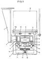
- Numeral 1 in Fig. 1 designates frames which are laid continuously on a track so as to extend in a longitudinal direction of the track. Brackets 2 suspended from a ceiling or the like are coupled to one side of the frames 1 to support them in a cantilever manner. A shock absorbing material 3 is interposed as necessary between the frame 1 and the bracket 2.
- a pair of rails 4 made of a ferromagnetic material are mounted on the bottom of the frame 1 at both sides thereof. They are attracted to floating magnets 12.
- Stators 5 of a linear motor for generating a driving force in forward and reverse directions are accommodated in a center recess of the frame 1 with its front side down at predetermined spacings along the track.
- the stators 5 have their bottom portions protruding from cutouts formed in the bottom of the frame so that their protruding bottom surfaces are substantially at the same level as the bottom surfaces of the rails 4.
- the frames 1 may not be box-shaped ones as illustrated. But the box-shaped frames are advantageous in that they can be assembled easily and that cables for power supply and control can be passed through cavities thereof.
- a carriage 10 carries four pairs of floating magnets 12 on its body 11, each pair at one of the four corners. Two each pairs are mounted on each of two beams 13 provided at front and rear of the body 11 of the carriage 10.
- the beams 13 are mounted to make a see-saw motion about a central horizontal axis and a steering motion (horizontal pivoting motion) about a central vertical axis.
- Gap sensors 14 are mounted on both ends of each beam 13 at front or rear of the magnets 12 so as to be located opposite to the bottom faces of the respective rails 4.
- a secondary conductor plate 15 of the linear motor is fixed to the body 11 so as to extend parallel thereto at substantially the same level as the pole surface of the magnets 12.
- the conductor plate 15 is preferably of a sufficient length in driving and stopping the carriage 10. For this purpose, in the embodiment, it extends across the beams 13 between the magnets 12 and terminates at the front and rear ends of the body 11.
- Support members 16 have one end thereof secured to the body 11 and the other end extending upwards along the other side of the frame 1 so that their ends are located higher than the top surface of the frame 1.
- a pallet 17 is secured to the top end of the support members 16 in a cantilever manner. The center of the pallet 17 with respect to the direction of width is located right over the center of the body 11 of the carriage to keep the balance of the load.
- the support member 16 is in the form of two pillars but may be one made by bending a plate-shaped member.
- the pallet 17 should preferably be provided along the edge thereof with stoppers 17a to prevent a load W from falling off.
- Shock absorbing devices 18 are provided at front and rear ends of the body 11 of the carriage 10 to lessen the shock when a carriage bumps against another carriage from behind. Though these elements are preferable, they may be omitted because the risk of car-to-car collisions is not very high.
- a cover 6 as shown by chain line in Fig. 1 may be provided to cover the bottom part of the carriage 10 facing the track. It serves to prevent dust on the track from scattering.
- Rollers 19 may be mounted on the bottom of the pallet 17 so that they will land on the frame 1 when they descend a distance G from the elevated position (Fig. 1). With this arrangement, even if the carriage body should move by inertia after it has stopped from floating, there will be no friction between the pallet 17 and the frame 1, which is a major cause of the production of dust.
- the rollers 19 may be mounted on the car body 11 so that they bear on the cover 6. Irrespective of whether the rollers 19 are supported on the frame 1 or on the cover 6, the gap G or the amount of descent of the car body when the attraction force stops should not exceed the range within which the car body can be floated up again by the attraction force of the floating magnets 12.
- rollers 20 should be adapted to abut bottom guide surfaces before the magnets 12 contact the rails 4 to prevent the carriage body from moving further up and thus to prevent the production of dust.
- the bottom surfaces of the rails 4 also serve as the guide surfaces against which the rollers 20 are adapted to abut.
- the carrier system according to this invention can prevent the load from falling or being polluted because it is mounted on the pallet 17. Also, loading and unloading are easy.
- Fig. 4 shows a branch portion of the track by way of example.
- the only requirement for such a branch portion is the provision of a gap l large enough to allow the passage of the support member 16 between the main track 7 and the branch track 7a.
- the carriage body will never fall at such branch portions unlike the conventional systems in which the guide rails had to be cut off partially at the branch points.
- a stator for driving it sideways may be provided at side of the stator 5 to drive it with the linear motor. Otherwise, the carriage may be pulled with a retractable arm or cylinder.
- the pallet 17 may be supported on rails 8 and 4a (according to the positions of the gap sensors, the rails 8 may have to be provided not inside but outside the rails 4a). Otherwise, if the cover 6 is provided, the carriage body 11 may be supported on the cover 6. In the figure, the rails 4a are fixed on the ground, with the rails 8 supported at one side thereof on the rails 4a. The pallet 17 is placed on the top of the rails 8.
- the branch track 7a or the side track 7b may be moved to eliminate the gap l between the main track 7 and the branch track 7a or side track 7b and thus to stabilize the transition movements.
- the carriage body 11 might roll. If the pallet turns automatically in a direction opposite to the direction of the rolling motion by the same angle as the rolling angle, the pallet will not get inclined.
- Figs. 6-8 show specific examples of a balancer having such an automatic balancing function.
- a balancer 21 shown in Fig. 6 comprises a horizontal frame 23 mounted on the top end of the support member 16, and bearings 24 mounted on the frame 23 so as to be symmetrical with respect to the center of the carriage body.
- a rocking frame 25 carrying the pallet 17 has an arcuate bottom surface 25a, which is supported on the bearings 24. If the carriage body 11 rolls and inclines, the rocking frame 25 will automatically turn sideways by gravity to the point where the load is balanced in the transverse direction, thus keeping the pallet 17 always in its horizontal position.
- Fig. 7 shows another type of balancer 22 in which the support member 16 comprises a pair of front and rear struts shown in Fig. 2.
- Front and rear suspension frames 26 have their top ends coupled to the top ends of the struts by means of pivot shafts 27, which are provided with seals 30 to prevent the production of dust.
- the seals 30 include seals covering the friction portions of the shafts 27 and ones for reducing the production of dust itself by reducing the frictional resistance of the shafts. With this arrangement, the portions where dust is produced can be reduced compared with the balancer 21 of Fig. 6.
- a balancer 22' shown in Fig. 8 is in the form of a suspension frame 28 comprising transversely movable horizontal links 28a and vertical links 28b hung on both ends of the horizontal links 28a.
- the frame 28 is supported on the support member 16 by means of shafts 27 at the center of the carriage body.
- the links 28 are coupled together through coupling means 29 having seals 30 for preventing the production of dust.
Landscapes
- Non-Mechanical Conveyors (AREA)
- Control Of Vehicles With Linear Motors And Vehicles That Are Magnetically Levitated (AREA)
Applications Claiming Priority (2)
| Application Number | Priority Date | Filing Date | Title |
|---|---|---|---|
| JP318855/90 | 1990-11-20 | ||
| JP2318855A JP2984359B2 (ja) | 1990-11-20 | 1990-11-20 | 磁気浮上搬送システム及び同システム用搬送車 |
Publications (2)
| Publication Number | Publication Date |
|---|---|
| EP0487038A1 true EP0487038A1 (fr) | 1992-05-27 |
| EP0487038B1 EP0487038B1 (fr) | 1995-07-12 |
Family
ID=18103706
Family Applications (1)
| Application Number | Title | Priority Date | Filing Date |
|---|---|---|---|
| EP91119743A Expired - Lifetime EP0487038B1 (fr) | 1990-11-20 | 1991-11-19 | Système de transport à sustentation magnétique |
Country Status (4)
| Country | Link |
|---|---|
| US (1) | US5197391A (fr) |
| EP (1) | EP0487038B1 (fr) |
| JP (1) | JP2984359B2 (fr) |
| DE (1) | DE69111194T2 (fr) |
Families Citing this family (11)
| Publication number | Priority date | Publication date | Assignee | Title |
|---|---|---|---|---|
| US6784572B1 (en) * | 1991-03-17 | 2004-08-31 | Anorad Corporation | Path arrangement for a multi-track linear motor system and method to control same |
| KR0151602B1 (ko) * | 1992-11-13 | 1998-10-15 | 마스다 쇼오이치로오 | 크린룸용 반송설비 |
| US7026732B1 (en) * | 1998-02-26 | 2006-04-11 | Anorad Corporation | Path arrangement for a multi-track linear motor system and method to control same |
| US9032880B2 (en) | 2009-01-23 | 2015-05-19 | Magnemotion, Inc. | Transport system powered by short block linear synchronous motors and switching mechanism |
| US8616134B2 (en) | 2009-01-23 | 2013-12-31 | Magnemotion, Inc. | Transport system powered by short block linear synchronous motors |
| JP5629084B2 (ja) * | 2009-11-17 | 2014-11-19 | 株式会社ミウラ | 搬送装置 |
| US9802507B2 (en) | 2013-09-21 | 2017-10-31 | Magnemotion, Inc. | Linear motor transport for packaging and other uses |
| DE102015209625A1 (de) * | 2015-05-26 | 2016-12-01 | Robert Bosch Gmbh | Transportvorrichtung |
| DE102015226139A1 (de) * | 2015-12-21 | 2017-06-22 | Krones Ag | Lineares Transportsystem mit minimaler Transportteilung |
| CN107892147B (zh) * | 2017-10-27 | 2020-01-10 | 安庆博鳌纵横网络科技有限公司 | 一种易碎物品的高空运输装置 |
| CN113400949B (zh) * | 2020-03-16 | 2023-06-13 | 中国航天科工飞航技术研究院(中国航天海鹰机电技术研究院) | 应急滑靴装置及具有其的电动磁悬浮悬浮架 |
Citations (3)
| Publication number | Priority date | Publication date | Assignee | Title |
|---|---|---|---|---|
| GB2029347A (en) * | 1978-08-24 | 1980-03-19 | Japan Airlines Co | Independent suspension system for magnetically supported travelling body |
| EP0141334A1 (fr) * | 1983-10-20 | 1985-05-15 | Götz Dipl.-Phys. Heidelberg | Installation de transport à la manière d'un convoyeur à bande |
| EP0179188A2 (fr) * | 1984-10-23 | 1986-04-30 | Kabushiki Kaisha Toshiba | Système de transport du type à support flottant |
Family Cites Families (7)
| Publication number | Priority date | Publication date | Assignee | Title |
|---|---|---|---|---|
| US2198668A (en) * | 1937-05-29 | 1940-04-30 | Chrysler Corp | Railway vehicle |
| US2440746A (en) * | 1945-03-10 | 1948-05-04 | Hereford Rockwell | Vehicle body mounting |
| DE2511382C2 (de) * | 1975-03-15 | 1983-10-06 | Messerschmitt-Boelkow-Blohm Gmbh, 8000 Muenchen | Magnetschwebefahrzeug mit federnd gelagerten Trag- und Führungsmagneten |
| DE3107341C2 (de) * | 1981-02-26 | 1985-08-01 | Magnet-Bahn Gmbh, 8130 Starnberg | Magnetschwebe-Fahrzeug mit gegenüber dem Tragteil abgefedertem Nutzlastträger |
| JPS6426113A (en) * | 1987-04-22 | 1989-01-27 | Sakiyama Seisakusho Kk | Flow amount meter |
| GB8714291D0 (en) * | 1987-06-18 | 1987-07-22 | Bicc Plc | Insulating liquids & electric cables |
| JP2549156B2 (ja) * | 1987-11-06 | 1996-10-30 | 住友電気工業株式会社 | 磁気浮上搬送装置における台車逸脱防止装置 |
-
1990
- 1990-11-20 JP JP2318855A patent/JP2984359B2/ja not_active Expired - Lifetime
-
1991
- 1991-11-19 EP EP91119743A patent/EP0487038B1/fr not_active Expired - Lifetime
- 1991-11-19 DE DE69111194T patent/DE69111194T2/de not_active Expired - Fee Related
- 1991-11-20 US US07/794,882 patent/US5197391A/en not_active Expired - Fee Related
Patent Citations (3)
| Publication number | Priority date | Publication date | Assignee | Title |
|---|---|---|---|---|
| GB2029347A (en) * | 1978-08-24 | 1980-03-19 | Japan Airlines Co | Independent suspension system for magnetically supported travelling body |
| EP0141334A1 (fr) * | 1983-10-20 | 1985-05-15 | Götz Dipl.-Phys. Heidelberg | Installation de transport à la manière d'un convoyeur à bande |
| EP0179188A2 (fr) * | 1984-10-23 | 1986-04-30 | Kabushiki Kaisha Toshiba | Système de transport du type à support flottant |
Non-Patent Citations (2)
| Title |
|---|
| IEEE TRANSACTIONS ON VEHICULAR TECHNOLOGY. vol. 38, no. 2, May 1989, NEW YORK US pages 102 - 108; AZUKIZAWA ETC: 'A linear induction motor control system for magnetically levitated carrier system' * |
| PATENT ABSTRACTS OF JAPAN vol. 13, no. 373 (M-861)18 August 1989 & JP-A-1 126 113 ( SUMIMOTO ) 18 May 1989 * |
Also Published As
| Publication number | Publication date |
|---|---|
| DE69111194D1 (de) | 1995-08-17 |
| JPH04185209A (ja) | 1992-07-02 |
| DE69111194T2 (de) | 1996-04-04 |
| US5197391A (en) | 1993-03-30 |
| JP2984359B2 (ja) | 1999-11-29 |
| EP0487038B1 (fr) | 1995-07-12 |
Similar Documents
| Publication | Publication Date | Title |
|---|---|---|
| US4289227A (en) | Belt conveyer transportation system utilizing magnetic attraction | |
| EP0487038B1 (fr) | Système de transport à sustentation magnétique | |
| US11084655B2 (en) | Vehicle for moving a container and system allowing such vehicle to move the container | |
| KR20150060800A (ko) | 숏 블럭 리니어 동기 모터 및 스위칭 메커니즘 | |
| TWI432370B (zh) | 磁力懸浮傳送系統 | |
| JP2760842B2 (ja) | リニア誘導モータ式搬送システム | |
| JPH0395021A (ja) | ブレーキ機構を備えたリニア搬送装置 | |
| JPS62225106A (ja) | リニアモ−タ利用の搬送設備 | |
| JPH0672539A (ja) | 荷搬送装置 | |
| JPH043341B2 (fr) | ||
| JP3348986B2 (ja) | 倒立搬送を可能にしたコンベヤ装置 | |
| JPH04117111A (ja) | 磁気浮上式搬送装置 | |
| KR200227123Y1 (ko) | 열연코일자동이송장치 | |
| JPH0493401A (ja) | 磁気浮上搬送車の軌道構造 | |
| JPH04222402A (ja) | 磁気浮上式搬送装置およびその分岐機構 | |
| JP2549156B2 (ja) | 磁気浮上搬送装置における台車逸脱防止装置 | |
| JPH08126123A (ja) | 磁気浮上搬送車の取出し方法 | |
| JPH02131301A (ja) | リニアモータ搬送装置 | |
| JPH04125007A (ja) | 磁気浮上式搬送装置 | |
| JPH03243524A (ja) | 搬送装置 | |
| JPH0556510A (ja) | リニアモータ式ワーク搬送装置 | |
| JPH04169415A (ja) | 磁気浮上式搬送装置 | |
| JPH01126113A (ja) | 磁気浮上搬送装置におけるマグネット懸架装置 | |
| JPH03276866A (ja) | 磁気吸引式浮上搬送装置 | |
| JPH02227364A (ja) | 磁気浮上搬送装置における台車逸脱防止装置 |
Legal Events
| Date | Code | Title | Description |
|---|---|---|---|
| PUAI | Public reference made under article 153(3) epc to a published international application that has entered the european phase |
Free format text: ORIGINAL CODE: 0009012 |
|
| AK | Designated contracting states |
Kind code of ref document: A1 Designated state(s): DE FR GB |
|
| 17P | Request for examination filed |
Effective date: 19920630 |
|
| 17Q | First examination report despatched |
Effective date: 19930625 |
|
| GRAA | (expected) grant |
Free format text: ORIGINAL CODE: 0009210 |
|
| AK | Designated contracting states |
Kind code of ref document: B1 Designated state(s): DE FR GB |
|
| REF | Corresponds to: |
Ref document number: 69111194 Country of ref document: DE Date of ref document: 19950817 |
|
| ET | Fr: translation filed | ||
| PLBE | No opposition filed within time limit |
Free format text: ORIGINAL CODE: 0009261 |
|
| STAA | Information on the status of an ep patent application or granted ep patent |
Free format text: STATUS: NO OPPOSITION FILED WITHIN TIME LIMIT |
|
| 26N | No opposition filed | ||
| PGFP | Annual fee paid to national office [announced via postgrant information from national office to epo] |
Ref country code: FR Payment date: 19981110 Year of fee payment: 8 |
|
| PGFP | Annual fee paid to national office [announced via postgrant information from national office to epo] |
Ref country code: GB Payment date: 19981120 Year of fee payment: 8 |
|
| PGFP | Annual fee paid to national office [announced via postgrant information from national office to epo] |
Ref country code: DE Payment date: 19981130 Year of fee payment: 8 |
|
| PG25 | Lapsed in a contracting state [announced via postgrant information from national office to epo] |
Ref country code: GB Free format text: LAPSE BECAUSE OF NON-PAYMENT OF DUE FEES Effective date: 19991119 |
|
| GBPC | Gb: european patent ceased through non-payment of renewal fee |
Effective date: 19991119 |
|
| PG25 | Lapsed in a contracting state [announced via postgrant information from national office to epo] |
Ref country code: FR Free format text: LAPSE BECAUSE OF NON-PAYMENT OF DUE FEES Effective date: 20000731 |
|
| PG25 | Lapsed in a contracting state [announced via postgrant information from national office to epo] |
Ref country code: DE Free format text: LAPSE BECAUSE OF NON-PAYMENT OF DUE FEES Effective date: 20000901 |
|
| REG | Reference to a national code |
Ref country code: FR Ref legal event code: ST |