EP0487751B1 - Brodeuse - Google Patents
Brodeuse Download PDFInfo
- Publication number
- EP0487751B1 EP0487751B1 EP91911193A EP91911193A EP0487751B1 EP 0487751 B1 EP0487751 B1 EP 0487751B1 EP 91911193 A EP91911193 A EP 91911193A EP 91911193 A EP91911193 A EP 91911193A EP 0487751 B1 EP0487751 B1 EP 0487751B1
- Authority
- EP
- European Patent Office
- Prior art keywords
- driving
- needle bar
- driving mechanism
- needle
- lever
- Prior art date
- Legal status (The legal status is an assumption and is not a legal conclusion. Google has not performed a legal analysis and makes no representation as to the accuracy of the status listed.)
- Expired - Lifetime
Links
- 238000009958 sewing Methods 0.000 title claims description 68
- 230000007246 mechanism Effects 0.000 claims description 101
- 230000033001 locomotion Effects 0.000 claims description 23
- 230000001133 acceleration Effects 0.000 claims description 2
- 239000004744 fabric Substances 0.000 description 18
- 210000002445 nipple Anatomy 0.000 description 8
- 238000010276 construction Methods 0.000 description 7
- 230000014509 gene expression Effects 0.000 description 7
- 230000009191 jumping Effects 0.000 description 6
- 238000010586 diagram Methods 0.000 description 3
- 230000005764 inhibitory process Effects 0.000 description 2
- 238000003780 insertion Methods 0.000 description 2
- 230000037431 insertion Effects 0.000 description 2
- 239000010985 leather Substances 0.000 description 2
- 230000005540 biological transmission Effects 0.000 description 1
- 230000015572 biosynthetic process Effects 0.000 description 1
- 230000006835 compression Effects 0.000 description 1
- 238000007906 compression Methods 0.000 description 1
- 238000000605 extraction Methods 0.000 description 1
- 230000009931 harmful effect Effects 0.000 description 1
- 239000000463 material Substances 0.000 description 1
- 238000000034 method Methods 0.000 description 1
- 238000012986 modification Methods 0.000 description 1
- 230000004048 modification Effects 0.000 description 1
- 230000002093 peripheral effect Effects 0.000 description 1
Images







Classifications
-
- D—TEXTILES; PAPER
- D05—SEWING; EMBROIDERING; TUFTING
- D05C—EMBROIDERING; TUFTING
- D05C5/00—Embroidering machines with arrangements for automatic control of a series of individual steps
- D05C5/02—Embroidering machines with arrangements for automatic control of a series of individual steps by electrical or magnetic control devices
-
- D—TEXTILES; PAPER
- D05—SEWING; EMBROIDERING; TUFTING
- D05C—EMBROIDERING; TUFTING
- D05C3/00—General types of embroidering machines
- D05C3/02—General types of embroidering machines with vertical needles
Definitions
- This invention relates to a multi-head embroidery machine mainly for industrial use.
- Each head of an embroidery machine of this kind includes various kinds of driving mechanisms such as a needle bar driving mechanism, a hook shaft driving mechanism and a thread take-up lever driving mechanism which are required for sewing operation.
- Document FR-A-2 621 612 discloses an embroidery machine wherein driving mechanisms required for embroidery sewing have different driving sources. Mechanisms for driving a needle in an angular and a vertical direction, respectively, have different motors in order to obtain a desired embroidery.
- US-A-4 557 206 shows a sewing machine in which a frame which is moved by to-and-fro feed device is provided to be movable forwards and backwards along a guide mechanism provided to a base.
- the sewing machine discloses two driving mechanisms having separate motors.
- US-A-3 515 080 discloses a sewing machine which embodies physically separated needle drive and bobbin drive units which cooperate to produce stitching in a workpiece.
- Each machine unit embodies its own servo drive means and the drive means are electrically coupled in sychronism so that the units may be operated in unison and moved together in prescribed directions without having any physical connection.
- US-A-4 373 458 shows a method and machine provided for controlling the orientation of one or more sewing instrumentalities with respect to a workpiece while also controlling the path of movement of the workpiece.
- One or more sewing instrumentalities are preferably rotated about an axis perpendicular to the plane in which the workpiece is moved.
- JP-A-61-217196 discloses an embroidery machine which owns a plurality of swivel-mounted stitching heads.
- a technical object of the present invention is to provide a multi-head embroidery machine in which degree of freedom of timing of operation, respectively the operational position of each of drive devices is considerably increased; appropriate sewing operations can be performed according to change of a work to be sewn; and desired appearances can be obtained for the same work to be sewn.
- an embroidery machine is constructed as follows:
- the invention provides a multi-head embroidery machine comprising: a plurality of sewing heads each including a needle bar driving mechanism for driving a needle bar, a thread take-up lever driving mechanism for driving a thread take-up lever, a presser foot driving mechanism for driving a presser foot, a shuttle driving mechanism for driving a shuttle; and at least two of said needle bar driving mechanism, said thread take-up lever driving mechanism, said presser foot driving mechanism and said shuttle driving mechanism having different driving sources.
- control device taking the operational position of the shuttle driving mechanism as a standard, for controlling the driving sources of the other driving mechanism being driven in relation with said operational position.
- the positions of the upper and lower dead points of the thread take-up lever and the motion thereof can be freely determined to adjust the tightness of stitches in association with the timing of the vertical movement of the needle bar.
- the degree of freedom of timing of operation, respectively operational positioning of the driving sources/mechanisms is considerably increased, so that it is possible to perform the appropriate sewing operation at high speed (including the adjustment of the stitches tightness), and various tones or various appearances of the embroidery can be obtained.
- FIG. 1 is a vertical sectional view of a sewing head according to a first embodiment
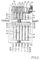
- Fig. 2 is a front view of the sewing head according to the first embodiment
- FIG. 3 is a sectional view, looking in the right-hand direction of FIG. 1, of driving mechanisms of the embroidery machine of the first embodiment
- FIG. 4 is a perspective view showing the whole appearance of an embroidery machine
- FIG. 5 is an explanatory view showing timings of operations of driving devices along with a timing of movement of frames
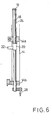
- FIG. 6 shows a sectional view where one of needle bars is used for boring
- FIG. 7 is a vertical sectional view, corresponding to FIG. 1, of a sewing head of a second embodiment
- FIG. 8 is a sectional view, looking in the right-hand direction of FIG. 7, of driving mechanisms of the second embodiment
- FIG. 9 is a vertical sectional view, corresponding to FIG. 1, of a sewing head of a third embodiment
- FIG. 10 is a sectional view, looking in the right-hand direction of FIG. 9, of driving mechanisms of the third embodiment
- FIG. 11 is a vertical sectional view of a main portion of a sewing head of a fourth embodiment
- FIG. 12 is a view, looking in the right-hand direction of FIG. 11, of a part of FIG. 11
- FIG. 13 is a vertical sectional view of a main portion of a sewing head of a fifth embodiment
- FIG. 14 is a view taken along line II-II in FIG. 13;
- FIG. 14 is a view taken along line II-II in FIG. 13;
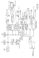
- FIG. 15 is a block diagram for controling an embroidery machine
- FIG. 16 is a circuit configuration of a needle bar driving mechanism
- FIG. 17 is a diagram showing the relationship between the rotational angle of a shuttle and the position of a pointed end of a needle
- FIG. 18 is a sectional view of a looper driving mechanism of an embroidery machine for loop sewing
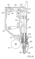
- FIG. 19 is a vertical sectional view of an embroidery machine having an additional function for sewing a cord or the like.
- FIG. 4 A schematic appearance of an embroidery machine is shown by a perspective view in FIG. 4.
- a plurality of sewing heads H (six in this figure) are mounted on the front side of a machine frame 10 disposed on a table 1 and are spaced from each other at a predetermined distance. The construction of each of the sewing heads H will now be explained.
- One of the sewing heads H is shown by a vertical sectional view in FIG. 1 and is shown by a front view in FIG. 2.
- the sewing head H is provided with an arm 12 and a needle bar casing 14.
- the needle bar casing 14 is disposed on the front side (right side in FIG. 1) of the arm 12 and is slidably movable in a lateral direction in FIG. 2 through a radial bearing 17 and a guide portion 13 of the arm 12.
- the rear portion (left side portion in FIG. 1) of the arm 12 is fixed to the machine frame 10.
- a plurality of needle bars 18 are vertically movably mounted on the needle bar case 14 and are spaced from each other in the lateral direction at a predetermined distance.
- a needle bar connecting stud 20 is fixed to the middle portion of each of the needle bars 18 and is provided with a protrusion 22 on the left side in FIG. 1.
- a needle bar support spring 24 is interposed between a spring seat 19 disposed at the upper end of each of the needle bars 18 and an upper surface of an upper horizontal frame 14a of the needle bar casing 14 for normally biasing the corresponding needle bar 18 in an upward direction.
- each of the needle bars 18 is kept at its upper dead point as shown by solid lines in FIGS. 1 and 2.
- a sewing needle 26 is mounted on the lower end of each of the needle bar 18.
- a needle bar base 40 is mounted on the arm 12 and extends in parallel to the needle bars 18.
- a driving member 42 is vertically movably mounted on the needle bar base 40.
- a pair of engaging protrusions 43 spaced from each other in the vertical direction are integrally formed with the driving member 42.
- the protrusion 22 of one of the needle bars 18 selected through aforementioned sliding movement of the needle bar casing 14 relative to the arm 12 is engageable between the engaging protrusions 43.
- Thread take-up levers 30 are disposed within the needle bar case 14 at positions corresponding to the needle bars 18, respectively. Each of the thread take-up levers 30 is rotatably mounted on a thread take-up lever shaft 34 supported by the needle bar casing 14 at both ends thereof. Further, each of the thread take-up levers 30 is provided with a gear 32 having the same central axis as that of the thread take-up lever shaft 34.
- a presser foot shaft 52 is vertically movably mounted on the arm 12 at a position rearwardly of the needle bar base 40 (leftward in FIG. 1) and extends in parallel to the neele bar base 40.
- a presser foot 50 is fixed to the lower end of the presser foot shaft 52 below the arm 12.
- a pin 54 is fixed to the presser foot shaft 52.
- a shuttle 60 is disposed below a throat plate 2 mounted on the table 1.
- a hook shaft 62 for rotating the shuttle 60 is rotatably supported by a frame 1a below the table 1, and a gear 64 is fixed to one end of the hook shaft 62.
- these driving mechanisms 70, 80, 90 and 100 include driving shafts 70A, 80A, 90A and 100A, respectively, and as shown in FIG. 4, the driving shafts 70A, 80A and 90A other than the driving shaft 100A extend through the sewing heads H, respectively.
- the driving shaft 100A of the hook driving mechanism 100A extends below the table 1.
- the driving mechanisms 70, 80, 90 and 100 are shown in FIG. 3 as right side sectional views of FIG. 1.
- the driving shafts 70A, 80A, 90A and 100A receive driving force from respective driving sources 70B, 80B, 90B and 100B such as servo-motors, independently of each other. Only the driving shaft 100A of the shuttle driving mechanism 100 is driven in one direction by the driving source 100B, while the other driving shafts 70A, 80A and 90A are driven in both forward and reverse directions by the driving sources 70B, 80B and 90B, respectively.
- the driving mechanisms 70, 80, 90 and 100 include absolute encoders 70C, 80C, 90C and 100C, respectively.
- a signal from the encoder 100C of the shuttle driving mechanism 100 is used as an operation reference for the other driving mechanisms 70, 80 and 90.
- a lever 72 is disposed within each of the sewing heads H and is mounted on the driving shaft 70A of the needle bar driving mechanism 70 in such a manner that the lever 72 rotates with the driving shaft 70A.
- the end portion of the lever 72 is connected to the driving member 42 through a link 74 and pins 75 and 76.
- the driving member 42 is vertically reciprocally moved along the needle bar base 40 as the driving shaft 70A rotates in the forward and reverse directions.
- a drive gear 82 is fixedly mounted on the driving shaft 80A.
- a part of the thread take-up rail 36 is notched at a position forwardly of the drive gear 82 (rightwardly in FIG. 1).
- the gear 32 of the thread take-up lever 30 positioned forwardly of the drive gear 82 through selecting operation of the needle bars 18 engages the drive gear 82 and is released from engagement with the thread take-up lever rail 36. Therefore, only the selected thread take-up lever 30 may rotate around the thread take-up lever shaft 34 by the reciprocal rotation of the driving shaft 80A.
- a lever 92 is mounted on the driving shaft 90A of the presser foot driving mechanism 90 in such a manner that it can be rotated with the driving shaft 90A.
- An engagement recess 94 is formed at one end of the lever 92 and is in engagement with the pin 54 of the presser foot shaft 52.
- the presser foot 50 moves vertically together with the presser foot shaft 52 by the reciprocal rotation of the driving shaft 90A.
- a drive gear 102 is fixedly mounted on the driving shaft 100A of the shuttle driving mechanism 100 and engages the gear 64 of the hook shaft 62.
- the shuttle 60 therefore rotates as the driving shaft 100A continuously rotates in one direction.
- a control device 110 shown in FIG. 3 is constructed by incorporating a microcomputer and its related devices.
- the control device 110 outputs signals to the drive sources 70B, 80B and 90B for controlling operational positions of the driving shafts 70A, 80A and 90A relative to the position of the driving shaft 100A of the hook shaft driving mechanism 100, based on signals from the absolute encoders 70C, 80C, 90C and 100C of the driving mechanisms 70, 80, 90 and 100.
- the control device 110 may be assembled into a servo-control system or may be disposed outside of the same as the case may be.
- FIG. 5 shows timings of operation of the driving mechanisms 70, 80, 90 and 100 as well as a timing for driving an embroidery frame.
- the dotted line shows the case of a conventional machine, while the solid line shows the case of this embodiment.
- the needle bar driving mechanism 70, the thread take-up lever driving mechanism 80 and the presser foot driving mechanism 90 are driven at predetermined timings as shown in FIG. 5 with the driving timing of the shuttle driving mechanism taken as a standard.
- the driving member 42 reciprocally vertically moves along the needle bar base 40 according to the movement of the lever 72 which rotates with the driving shaft 70A.
- the driving shaft 80A of the thread take-up lever driving mechanism 80 rotates with the drive gear 82
- the thread take-up lever 30 corresponding to the above selected needle bar 18 reciprocally rotates around the thread take-up lever shaft 34.
- the driving shaft 90A of the presser foot driving mechanism 90 rotates, the presser foot shaft 52 is vertically moved together with the presser foot 50 through the lever 92 which reciprocally rotates with the driving shaft 90A.
- the needle bar driving mechanism 70 As will be seen from FIG. 5, the period during which the needle bar 18 (the sewing needle 26) is positioned above the upper surface of a fabric to be sewn can be determined to have a long time. Therefore, this may provide sufficient time for the timing of movement of the frame. Further, the timing of the vertical movement of the needle bar 18 can be freely changed according to kinds of sewing or works to be sewn.
- the rotational angle of the driving shaft 70A of the needle bar driving device 70 can be changed to adjust the stroke of vertical movement of the needle bar 18.
- the vertical stroke can be determined as shorter as possible by lowering the position of the upper dead point of the needle bar 18, while during exchanging operation of the fabric, the efficiency of operation can be increased by greatly lifting the needle bar 18.
- FIG. 6 shows a sectional view of an embodiment where a boring device 28 is mounted on one of the needle bars 18 within the needle bar casing 14.
- the boring device 28 is provided to bore the fabric through driving of the needle bar 18 and has a tapered configuration pointed at its extremity.
- the boring device 28 is mounted normally on the first needle bar 18 which is located in the most rightward position in FIG. 2.
- the vertical stroke of the needle bar 18 having the boring device 28 in such a manner as described above, the depth of sticking of the boring device 28 into the fabric can be changed.
- the size of a bore formed in the fabric by the boring device 28 through one vertical stroke of the needle bar 18 can be adjusted.
- the thread take-up lever driving mechanism 80 by independently driving the same, the positions of upper and lower dead points of the thread take-up 30 and the motion thereof can be freely determined, so that the tightness of stitches can be adjusted in association with the timing of the vertical movement of the needle bar 18.
- shrinkage may be prevented by changing the stroke of the thread take-up lever according to the length of the stitch or by increasing the stroke of the thread take-up lever in proportion to the length of the stitch.
- an economical driving operation can be performed by determining the vertical stroke of the presser foot 50 as shorter as possible. Further, by determining the stroke of the presser foot 50 to the minimum required length and by determining the acceleration at the upper and lower dead points to minimum values, it can reduce vibrations and noises during sewing operation. This may be also applicable to the needle bar 18. Further, as is also the case with the needle bar 18, the presser foot 50 can be substantially lifted above the work to be sewn when the work to be sewn is exchanged.
- the needle bar 18 undergoes a large resistance when it is moved upwardly to be extracted from the work to be sewn.
- FIGS. 7 and 8 show sectional views corresponding to FIGS. 1 and 2, respectively.
- a drive pulley 104 is mounted on a driving shaft 100A of a shuttle driving mechanism 100 in such a manner that it rotates integrally with the driving shaft 100A.
- a needle bar driving mechanism 70 is not provided with a driving source such as a servo-motor but is provided with a driven pulley 78 mounted on a driving shaft 70A.
- a timing belt 120 is tensioned between the drive pulley 104 and the driven pulley 78.
- the needle bar driving mechanism 70 continuously rotates in one direction through interlocking with the driving shaft 100A of the shuttle driving mechanism 100.
- a lever 72 of the needle bar driving mechanism 70 is pivotally mounted on a support shaft 122, and a cam 124 is mounted on the driving shaft 70A.
- a ring-like portion formed on one end of a connecting rod 126 is connected to an outer periphery of the cam 124.
- the other end of the rod 126 is connected to substantially the central portion of the lever 72 through a pin. Therefore, as the driving shaft 70A rotates, the lever 72 is pivoted around the support shaft 122 through the operations of the cam 124 and the connecting rod 126.
- the driving member 42 is reciprocally vertically moved along a needle bar base 40 as was discribed in connection with the first embodiment through interlocking with the pivotal movement of the lever 72.
- the needle bar driving mechanism 70 and the shuttle driving mechanism 100 are interconnected with each other, while only a thread take-up lever driving mechanism 80 and a presser foot driving mechanism 90 are independently driven, respectively.
- FIGS. 9 and 10 A third embodiment is shown in FIGS. 9 and 10 by sectional views corresponding to FIG. 1 and FIG. 2.
- the presser foot driving mechanism 90 of the second embodiment is omitted.
- a presser foot 50 is vertically movably mounted on each needle bar 18.
- a coil spring 56 is interposed between the presser foot 50 and a needle bar connecting stud 20 as previously described.
- the presser foot 50 When the needle bar 18 is caused to move downwardly through interlocking with driving of a driving member 42, the presser foot 50 is also moved downwardly through the spring 56. After movement of the presser foot 50 has been restricted at a fabric pressing position through abutment on a lower dead point stopper 58 of a needle bar casing 14, only the needle bar 18 moves downwardly to reach a lower dead point through compression of the spring 56. When the needle bar 18 is moved upwardly, a needle clamp body 29 disposed at its lower end abuts on the presser foot 50, and thereafter, the presser foot 50 moves upwardly together with the needle bar 18.
- a needle bar driving mechanism 70 is interlocked with a shuttle driving mechanism 100 and the presser foot 50 is interlocked with the needle bar 18, and therefore, only a thread take-up lever driving mechanism 80 is independently driven.
- FIGS. 11 and 12 show an embodiment incorporating a jumping mechanism on the basis of the construction of the first embodiment.
- a jumping operation can be performed by temporarily releasing driving of a needle bar driving mechanism 70 and a presser foot driving mechanism 90.
- a vertically movable member 41 and a driving member 42 as previously described are mounted on a needle bar base 40 and are movable together along the needle bar base 40 in a vertical direction.
- the driving member 42 is rotatable around the axis of the needle bar base 40 for disengaging its engagement protrusion 43 from a protrusion 22 of a needle bar 18.
- a lever 72 is connected to the vertically movable member 41 through a link 74 and pins 75 and 76.
- a guide rod 46 is disposed adjacent a presser foot shaft 52, and a vertically movable member 47 and a driving member 48 are mounted on the guide rod 46 and are movable together along the guide rod 46.
- a pair of engagement protrusions 49 are formed with the driving member 48 and are in engagement with a pin 54 of the presser foot shaft 52.
- the driving member 48 can also be rotated around the axis of the guide rod 46 for disengaging the engagement protrusions 49 from the pin 54 of the presser foot shaft 52.
- a lever 92 of the presser foot driving mechanism as previously described is connected to the vertically movable member 47 through a link 96, and pins 97 and 98.
- solenoids 130 are disposed adjacent upper dead points of the driving members 42 and 47, respectively.
- Plungers 132 may extend as shown by a virtual line when the solenoids 130 are excited.
- the plungers 132 thus extended may contact beveled surfaces 42a and 48a of the driving members 42 and 48 which have been moved to upward positions, respectively.
- the driving members 42 and 48 therefore rotate as described above, so that power transmission to the needle bar 18 and the presser foot shaft 52 can be interrupted.
- the jumping operation can be also performed by temporarily stopping the driving source 70C of the needle bar driving mechanism 70 in the first embodiment.
- the driving of the needle bars 18 of all of the sewing heads H in the multi-head sewing machine is released. Therefore, it requires to incorporate the aforesaid jumping device for controlling each of the sewing heads in such a manner that any of the sewing heads H can be stopped.
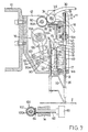
- FIG. 13 is a vertical sectional view of a sewing head H according to this embodiment
- FIG. 14 is a sectional view taken along line II-II in FIG. 13.
- the sewing head H is provided with an arm 12 and a needle bar casing 14.
- the needle bar casing 14 is disposed on the front side (right side in FIG. 13) of the arm 12 and is slidably movable in a lateral direction in FIG. 14 through a radial bearing 17 and a guide portion 13 of the arm 12.
- the rear portion (left side portion in FIG. 1) of the arm 12 is fixed to the machine frame 10.
- a plurality of needle bars 18 are vertically movably mounted on the needle bar case 14 and are spaced from each other in the lateral direction in FIG. 14 at a predetermined distance.
- a needle bar connecting stud 20 is fixed to the middle portion of each of the needle bars 18 and is provided with a protrusion 22 on the left side in FIG. 13.
- a needle bar support spring 24 is interposed between a spring seat 19 disposed at the upper end of each of the needle bars 18 and an upper surface of an upper horizontal frame 14a of the needle bar casing 14 for normally biasing the corresponding needle bar 18 in an upward direction.
- each of the needle bars 18 is kept at its upper dead point shown by a solid line in FIG. 13.
- a sewing needle 26 is mounted on the lower end of each of the needle bar 18.
- a needle bar base 40 is mounted on the arm 12 and extends in parallel to the needle bars 18.
- a driving member 42 is vertically movably mounted on the needle bar base 40.
- a pair of engaging protrusions 43 spaced from each other in the vertical direction are integrally formed with the driving members 42.
- the protrusion 22 of one of the needle bars 18 selected through aforementioned sliding movement of the needle bar casing 14 relative to the arm 12 is engageable between the engaging protrusions 43.
- a lever 72 is connected to the driving member 42 through a link 74 and pins 75 and 76, while the other end of the lever 72 is fixed to a needle bar driving shaft 70A, so that the lever 72 can be rotated with the driving shaft 70A.
- the driving member 42 reciprocally vertically moves along the needle bar base 40 and consequently, the needle bar 18 is reciprocally vertically moved.
- Thread take-up levers 30 are disposed within the needle bar case 14 at positions corresponding to the needle bars 18, respectively. Each of the thread take-up levers 30 is rotatably mounted on a thread take-up lever shaft 34 supported by the needle bar casing 14 at both ends thereof. Further, each of the thread take-up levers 30 is provided with a gear 32 having the same central axis as that of the thread take-up lever shaft 34.
- a drive gear 82 is fixedly mounted on the driving shaft 80A.
- a part of the thread take-up rail 36 is notched at a position forwardly of the drive gear 82 (rightwardly in FIG. 13).
- the gear 32 of the thread take-up lever 30 positioned forwardly of the drive gear 82 through selecting operation of the needle bars 18 engages the drive gear 82 and is released from engagement with the thread take-up lever rail 36. Therefore, only the selected thread take-up lever 30 may rotate around the thread take-up lever shaft 34 by the reciprocal rotation of the driving shaft 80A.
- a presser foot shaft 52 is vertically movably mounted on the arm 12 at a position rearwardly of the needle bar base 40 (leftward in FIG. 13) and extends in parallel to the needle bar base 40.
- a presser foot 50 is fixed to the lower end of the presser foot shaft 52 below the arm 12.
- a pin 54 is fixed to the presser foot shaft 52.
- a lever 92 is mounted on the driving shaft 90A of the presser foot driving mechanism 90 in such a manner that it can be rotated with the driving shaft 90A.
- An engagement recess 94 is formed at one end of the lever 92 and is in engagement with the pin 54 of the presser foot shaft 52.
- the presser foot 50 moves vertically together with the presser foot shaft 52 by the reciprocal rotation of the driving shaft 90A.
- a shuttle 60 is disposed below a throat plate 2 mounted on the table 1.
- a hook shaft 62 for rotating the shuttle 60 is rotatably supported by a frame 1a below the table 1.
- a needle bar driving mechanism 70 and a shuttle driving mechanism 100 will now be explained.
- one end of the needle bar driving shaft 70A is connected to a pulse motor 70B fixedly mounted on an outer surface of the arm 12 so as to receive reciprocal rotational movement from the pulse motor 70B.
- the pulse motor 70 constitutes a needle bar driving motor.
- an absolute encoder 70C is connected to a rotational shaft (not shown) of the pulse motor 70B, and the absolute encoder 70C makes it possible to detect a rotational angle of the pulse motor 70B or to indirectly detect the position of a pointed end of the sewing needle 26.
- a hook shaft 62 is connected to a pulse motor 100B fixedly mounted on the frame 1a so as to receive continuous rotational movement in one direction from the pulse motor 100B.
- an absolute encoder 100C is connected to a rotational shaft (not shown) or the pulse motor 100B, and the absolute encoder 100C makes it possible to detect a rotational angle of the pulse motor 100B or to indirectly detect a rotational angle of a shuttle 60.
- absolute encoder 100C constitutes a device for detecting the rotational angle of the shuttle.
- the thread take-up lever driving shaft 80A and the presser foot driving shaft 90A are independently driven by pulse motors 80B and 90B, respectively.
- FIG. 15 shows a control diagram for one of the sewing heads H according to this embodiment.
- the rotational angle of the shuttle 60 is detected by the absolute encoder 100C and is inputted to the CPU 400 through an interface 200C for the encoder.
- the CPU 400 calculates a rotational angle of the pulse motor 70B of the needle bar driving mechanism 70 for controlling the position of the sewing needle 26, and it converts the calculated value to a pulse signal and outputs the same to a driver 270M for the needle bar driving mechianism through an interface 300 for each pulse motor.
- the driver 270B Based on the inputted pulse signal, the driver 270B outputs an electric power for rotating the pulse motor 70A at a predetermined angle.
- FIG. 16 shows a circuit configuration of the driver 270B. Since this circuit is one generally utilized as a circuit for driving a motor, an explanation will be made in brief.
- the pulse signal inputted from a DP terminal is supplied to clock terminals CL1 and CL2 of a D-type flip-flop circuit 272.
- the D-type flip-flop circuit 272 converts the pulse signal to signals corresponding to the exciting state of each of coils MC1, MC2, MC3 and MC4 of the pulse motor 70B and outputs the same from terminals Q1, Q2, Q3 and Q4.
- the output signals from the terminals Q1, Q2, Q3 and Q4 are inputted, via a buffer circuit 276, to transistors Tr1, Tr2, Tr3 and Tr4 for supplying power to the coils MC1, MC2, MC3 and MC4, respectively.
- the state of exciting of each of the coils MC1, MC2, MC3 and MC4 is thus controlled and the pulse motor 70 is rotated step by step to reach the predetermined angle according to the number of the pulses inputted.
- the pulse motor 70B it is rotated by an angle of 1.8° for one pulse of the pulse signal inputted through the DP terminal.
- a mono-stable multivibrator 278 controls (for inhibition or for releasing inhibition) operation of the buffer circuit 276 based on the inputted pulse signal from the DP terminal.
- a signal for converting direction of rotation of the pulse motor 70B is inputted to a CW/CC terminal.
- the state of conduction of S1 and S2 of a non-inversion buffer circuit 274 is inverted and the state of connection of the D-type flip-flop circuit 272 is changed.
- the state of exciting of the coils MC1, MC2, MC3 and MC4 with respect to the inputted pulse signal is therefore converted and the direction of rotation of the pulse motor 70B is reversed.
- the driver 270B, the interface 300 for each pulse motor and the CPU, etc. function as a motor operating device.
- FIG. 17 shows the relation between rotational angle of the shuttle 60 X 1/2 (x) and position of the pointed end of the sewing needle (y).
- the reason why (x) has been determined as the rotational angle of the shuttle 60 X 1/2 is that a hook intersects with the pointed end of the needle at one time for each two revolutions of the shuttle 60 (a hook timing).
- the above expressions (for sections A to B) between the position of the pointed end the needle (y) and the rotational angle of the hook shaft 62 X 1/2 are stored in a ROM 410. Based on the above expressions, the CPU 400 calculates the rotational angle of the pulse motor 70B relative to the rotational angle of the hook shaft 62.
- the parameters Ra - Re, Aa - Ae and Ba - Be are stored in a RAM 420 or the ROM 410 and are freely determined in consideration of the work to be sewn or other conditions.
- the time during the sewing needle 26 is positioned below the surface of the fabric (sections A, B ) or the time between a needle insertion timing and a needle extraction timing (a needle inserting period) can be minimized according to the work to be sewn or other conditions. This may provide enough time for driving the embroidery frame in which its operation is limited during insertion of the sewing needle 26.
- the pulse motor 70B is provided for each sewing head H, in case that it is not necessary to insert the sewing needle for one of the sewing heads H, it is possible to keep the sewing needle of this one of the sewing heads H extracted during operation of the other of the sewing heads H. Therefore, it is not necessary to provide a jumping device or the like which was required for the conventional machine to keep the needle bar at idling state.
- FIG. 18 shows a looper driving mechanism of an embroidery machine for chain stitch sewing with a part broken away.
- a rotational shaft 506 is disposed within a looper base 502 and is substantially horizontally supported by a bearing 504.
- a looper driving gear 508 is fixed at substantially the central position of the rotational shaft 506.
- a pulse motor 510 is connected to one end of of the rotational shaft 506, and the rotational shaft 506 and the looper driving gear 508 are rotated by the pulse motor 510 at a predetermined angle around their axes.
- the looper driving gear 508 engages a looper driven gear 512 having substantially cylindrical configuration and is supported perpendicular to the rotational shaft 506.
- a crochet needle 514 is coaxially disposed above the looper driven gear 512. By a driving mechanism (not shown), the crochet needle 514 is vertically driven and is rotated around its axis to adjust the orientation of its crochet portion.
- the crochet portion of the crochet needle 514 is adjusted to be oriented in a sewing direction.
- the looper driven gear 512 is rotated by the pulse motor 510 in such a manner that a reference point (not shown) of the looper driven gear 512 is oriented in the same direction as the crochet portion of the crochet needle 514.
- the crochet needle 512 is subsequently moved downwardly and is inserted into a hollow portion of the looper driven gear 512 through sticking into a fabric to be sewn (not shown).
- a thread is guided into the hollow portion of the looper driven gear 512 which is rotated by the pulse motor 510 at a predetermined angle so as to round the thread around the crochet needle 514.
- the thread is engaged by the chrochet portion and is taken up to reach a position above the fabric to be sewn.
- the fabric to be sewn is moved at a predetermined distance, and the thread is drawn by the length corresponding to this distance.
- the crochet needle 514 is again moved downwardly so as to be stuck into the fabric to be sewn, resulting in that the thread is disengaged from the hook portion and that only the crochet needle 514 is inserted into the hollow portion of the looper driven gear 512.
- the looper driven gear 512 is thereafter rotated so as to round another part of the thread around the crochet needle 514.
- the thread thus newly rounded around the crochet needle 514 is taken up to reach a position above the fabric to be sewn and a stitch previously sewn.
- the same operation is subsequently repeated to form chain stitch embroidery.
- the pulse motor 514 performed control of rotation of the crochet needle 514 to orient its crochet portion in the same direction as that of the reference point of the looper driven gear 512
- the rotation of the looper driven gear 512 at the predetermined angle for rounding the thread around the crochet needle 514 is performed by interlocking with rotation of a main shaft of the machine.
- the rotation of the looper driven gear 512 is completely controlled by the pulse motor 510, so that the machine may have a simple construction. Further, since it is free to determine the rotational angle of the looper driven gear 512 relative to the crochet needle 514 according to the size, hardness and other factors of the thread, the range of selection of the material of the thread becomes broader.
- FIG. 19 is a vertical sectional view of an embroidery machine having additional function to sew a tape or a cord (or the like) on a fabric.
- a nipple 604 acting as a presser foot and a nipple guide 606 for supporting the nipple 604 are movably mounted on one end of a needle bar 602.
- the nipple guide 606 is inserted into a nipple sleeve 608 one end of which is fixed to an arm 612.
- a bush 610 for rotating a bobbin 614 is mounted on an outer surface of the nipple sleeve 608 and is rotatable around the nipple sleeve 608.
- the cord or the like is wound around the bobbin 614, and the bobbin 614 and an guide arm 618 are mounted on the bush 610.
- the cord or the like wound around the bobbin 614 extends to reach one end of the nipple 604 through a cylindrical cord guide 616 fixed to one end of the guide arm 618.
- a gear 611 is formed on the outer peripheral portion of the upper end of the bush 610 and engages a vertical shaft lower gear 621 formed on the lower end of a vertical shaft 620.
- a vertical shaft upper gear 622 is formed on the upper end of the vertical shaft 620 and engages a front end gear 625 of an upper shaft 624.
- a rear end gear 626 formed on the rear end of the upper shaft 624 engages a gear formed on a drive shaft 631 of a pulse motor 630 fixed to an outer lateral surface of the arm 612. With this construction, rotation of the pulse motor 630 is transmitted to the bush 610 through the upper shaft 624 and the vertical shaft 620.
- the bush 610 is rotated according to a sewing pattern, and the rotation of the pulse motor 630 is controlled in such a manner that the cord guide 616 is always oriented toward the sewing direction.
- the operation of the needle bar 602 is the same as that of an ordinary embroidery machine.
- the driving mechanisms 80 and 90 of the second embodiment shown in FIGS. 7 and 8 which are independently driven, respectively, and the driving mechanism 80 of the third embodiment shown in FIGS. 9 and 10 which are independently driven can be replaced by the other driving mechanisms.
Landscapes
- Engineering & Computer Science (AREA)
- Textile Engineering (AREA)
- Sewing Machines And Sewing (AREA)
Claims (4)
- Brodeuse à têtes multiples comprenant :
une pluralité de têtes de couture (H), incluant chacune un mécanisme d'entraínement (70) de barre à aiguille pour entraíner une barre à aiguille (18), un mécanisme d'entraínement (80) de levier releveur de fil pour entraíner un levier releveur de fil (30), un mécanisme d'entraínement (90) de pied presseur pour entraíner un pied presseur (50), un mécanisme d'entraínement (100) de navette pour entraíner une navette (60) ; et au moins deux dudit mécanisme d'entraínement (70) de barre à aiguille, dudit mécanisme d'entraínement (80) de levier releveur de fil, dudit mécanisme d'entraínement (90) de pied presseur et dudit mécanisme d'entraínement (100) de navette, ayant différentes sources d'entraínement (70B, 80B, 90B, 100B), caractérisée par un dispositif de contrôle (110) prenant la position fonctionnelle du mécanisme d'entraínement (100) de navette comme norme, pour contrôler les sources d'entraínement (70B, 80B, 90B) des autres mécanismes d'entraínement (70, 80, 90) entraínés par rapport à ladite position fonctionnelle, dans laquelle les positions des points morts supérieur et inférieur du levier releveur de fil (30) et le mouvement de celui-ci peuvent être fixés librement pour ajuster la tension des points de couture en association avec la synchronisation du mouvement vertical de la barre à aiguille (18). - Brodeuse à têtes multiples selon la revendication 1, caractérisée en ce que la synchronisation du mouvement vertical de la barre à aiguille (18) peut être modifiée librement selon les types de couture ou des ouvrages à coudre.
- Brodeuse à têtes multiples selon l'une des revendications 1 ou 2, caractérisée en ce que la course verticale du pied presseur (50) est fixée de façon a être aussi courte que possible et en ce que l'accélération au niveau des points morts supérieur et inférieur est fixée à des valeurs minimales.
- Brodeuse à têtes multiples selon l'une des revendications 1 à 3, caractérisée en ce que le mécanisme d'entraínement (70) de la barre à aiguille est asservi au mécanisme d'entraínement (100) de navette.
Applications Claiming Priority (7)
| Application Number | Priority Date | Filing Date | Title |
|---|---|---|---|
| JP158913/90 | 1990-06-18 | ||
| JP15891390 | 1990-06-18 | ||
| JP15891390A JPH0451991A (ja) | 1990-06-18 | 1990-06-18 | 刺繍ミシン |
| JP14947691A JPH04347192A (ja) | 1991-05-23 | 1991-05-23 | 刺繍ミシン |
| JP14947691 | 1991-05-23 | ||
| JP149476/91 | 1991-05-23 | ||
| PCT/JP1991/000809 WO1991019846A1 (fr) | 1990-06-18 | 1991-06-17 | Brodeuse |
Publications (3)
| Publication Number | Publication Date |
|---|---|
| EP0487751A1 EP0487751A1 (fr) | 1992-06-03 |
| EP0487751A4 EP0487751A4 (en) | 1992-11-25 |
| EP0487751B1 true EP0487751B1 (fr) | 1999-08-18 |
Family
ID=26479351
Family Applications (1)
| Application Number | Title | Priority Date | Filing Date |
|---|---|---|---|
| EP91911193A Expired - Lifetime EP0487751B1 (fr) | 1990-06-18 | 1991-06-17 | Brodeuse |
Country Status (4)
| Country | Link |
|---|---|
| US (1) | US5474001A (fr) |
| EP (1) | EP0487751B1 (fr) |
| DE (1) | DE69131534T2 (fr) |
| WO (1) | WO1991019846A1 (fr) |
Families Citing this family (41)
| Publication number | Priority date | Publication date | Assignee | Title |
|---|---|---|---|---|
| GB9123068D0 (en) * | 1991-10-30 | 1991-12-18 | British United Shoe Machinery | Machine suitable for use in operating on a workpiece |
| US5839382A (en) * | 1994-09-15 | 1998-11-24 | Tice Engineering And Sales, Inc. | Electronically geared sewing machine |
| JPH09140972A (ja) * | 1995-11-20 | 1997-06-03 | Brother Ind Ltd | ミシン |
| JPH09140980A (ja) * | 1995-11-20 | 1997-06-03 | Brother Ind Ltd | 縫製装置 |
| JPH09140974A (ja) * | 1995-11-20 | 1997-06-03 | Brother Ind Ltd | ミシン |
| JPH09140971A (ja) * | 1995-11-20 | 1997-06-03 | Brother Ind Ltd | ミシン |
| JP3156574B2 (ja) * | 1995-11-20 | 2001-04-16 | ブラザー工業株式会社 | ミシン |
| DE19709754B4 (de) * | 1996-03-11 | 2004-01-15 | Brother Kogyo K.K., Nagoya | Nähmaschine |
| US5832851A (en) * | 1996-03-11 | 1998-11-10 | Brother Kogyo Kabushiki Kaisha | Sewing machine |
| JPH09276579A (ja) * | 1996-04-08 | 1997-10-28 | Brother Ind Ltd | ミシン |
| DE19615308C1 (de) * | 1996-04-18 | 1997-07-17 | Pfaff Ag G M | Näh- oder Stickmaschine mit einer Fadenschneideinrichtung |
| DE19618667A1 (de) * | 1996-05-09 | 1997-11-13 | Zsk Stickmasch Gmbh | Stickmaschine mit auswechselbarem Stickkopf |
| US5953231A (en) * | 1997-12-22 | 1999-09-14 | Mcdonnell Douglas Corporation | Automated quality control for stitching of textile articles |
| US5931107A (en) * | 1997-12-22 | 1999-08-03 | Mcdonnell Douglas Corporation | Advanced stitching head for making stitches in a textile article having variable thickness |
| US5915317A (en) * | 1997-12-22 | 1999-06-29 | Thrash; Patrick J. | Automated gantry-type stitching system |
| US6198983B1 (en) | 1997-12-22 | 2001-03-06 | Mcdonnell Douglas Corporation | Table-driven software architecture for a stitching system |
| US6128545A (en) * | 1997-12-22 | 2000-10-03 | Mcdonnell Douglas Corporation | Automated apparatus and method of generating native code for a stitching machine |
| TW522192B (en) | 2000-05-25 | 2003-03-01 | Hankuk Special Prec Co Ltd | Embroidery machine |
| US6823807B2 (en) * | 2002-01-31 | 2004-11-30 | Melco Industries, Inc. | Computerized stitching including embroidering |
| US7308333B2 (en) * | 2002-01-31 | 2007-12-11 | Melco Industries, Inc. | Computerized stitching including embroidering |
| KR20030075737A (ko) * | 2002-03-20 | 2003-09-26 | 썬스타 특수정밀 주식회사 | 다두 자수기의 헤드 제어장치 및 제어방법 |
| KR200350914Y1 (ko) * | 2004-02-05 | 2004-05-17 | 썬스타 특수정밀 주식회사 | 자수기 |
| EP1766407A2 (fr) * | 2004-06-18 | 2007-03-28 | The Government of the United States of America, as represented by the Secretary of the Department of Health and Human Services | Procedes d'identification et d'utilisation de composes adaptes au traitement de cellules cancereuses resistantes aux medicaments |
| KR100577724B1 (ko) * | 2004-07-27 | 2006-05-08 | 썬스타 특수정밀 주식회사 | 단차형 자수기 |
| JP2007301299A (ja) * | 2006-05-15 | 2007-11-22 | Tokai Ind Sewing Mach Co Ltd | 多頭刺繍ミシン |
| EP1947227A1 (fr) * | 2007-01-17 | 2008-07-23 | Sunstar Precision Co., Ltd. | Mécanisme de bras de couture de machine à broder |
| EP2240175B1 (fr) * | 2008-02-11 | 2013-01-02 | The Government of the United States of America as represented by the Secretary of the Department of Health and Human Services | Composés à activité mdr1 inverse |
| IT1391048B1 (it) * | 2008-07-04 | 2011-10-27 | Vi Be Mac Spa | Macchina da cucire |
| CH700852A1 (de) * | 2009-04-28 | 2010-10-29 | Giuseppe Alfier | Vielnadel-Steppmaschine. |
| CN101988237B (zh) * | 2009-08-06 | 2013-05-29 | 北京大豪科技股份有限公司 | 电脑刺绣机的控制方法及设备 |
| KR101257750B1 (ko) * | 2011-04-21 | 2013-04-24 | 주식회사 스페이스솔루션 | 자수기 및 그 교정 방법 |
| CN102758316A (zh) * | 2011-04-25 | 2012-10-31 | 南京通孚轻纺有限公司 | 一种由计算机系统控制的绣花机 |
| DE102011118083A1 (de) * | 2011-11-10 | 2013-05-16 | Pfaff Industriesysteme Und Maschinen Ag | Nähmaschine mit einem Niederhalter für das Nähgut |
| CN102517809A (zh) * | 2011-12-14 | 2012-06-27 | 惠州神田精密机械有限公司 | 多头式电脑刺绣机及其控制系统 |
| CN102747556B (zh) * | 2012-08-10 | 2013-12-11 | 石狮市永信电脑设备制造有限公司 | 刺绣机刺绣粗线的圆弧型剪线工艺 |
| CN103361899B (zh) * | 2013-07-12 | 2014-05-21 | 宁波舒普机电科技有限公司 | 用于缝纫机的多针杆模块 |
| CN104073998A (zh) * | 2014-06-27 | 2014-10-01 | 重庆华依源电脑绣花厂 | 电脑绣花机工作台 |
| CN104060417A (zh) * | 2014-07-02 | 2014-09-24 | 苏州市叶绣工艺厂 | 一种无线刺绣系统 |
| CN104278451B (zh) * | 2014-10-31 | 2017-02-22 | 诸暨银河机电有限公司 | 图片刺绣机系统 |
| CN212175205U (zh) * | 2019-09-25 | 2020-12-18 | 浙江合和机电有限公司 | 一种独立压脚驱动机构及绣花机 |
| CN118273015A (zh) * | 2024-04-01 | 2024-07-02 | 浙江信胜科技股份有限公司 | 一种盘带绣装置及盘带绣花机 |
Family Cites Families (16)
| Publication number | Priority date | Publication date | Assignee | Title |
|---|---|---|---|---|
| US3515080A (en) * | 1968-01-08 | 1970-06-02 | Her Majesty Ind Inc | Electronically synchronized sewing machine |
| US3783811A (en) * | 1968-04-11 | 1974-01-08 | Bergenfield Dev Co Inc | Sewing machine |
| US3884165A (en) * | 1973-05-18 | 1975-05-20 | Ikuo Tajima | Needle-bar and take-up lever selection apparatus for embroidery machine |
| US4373458A (en) * | 1978-07-14 | 1983-02-15 | Usm Corporation | Method and machine for versatile stitching |
| US4215641A (en) * | 1979-07-05 | 1980-08-05 | The Singer Company | Electronic control of needle thread in a sewing machine |
| JPS6043145B2 (ja) * | 1982-02-23 | 1985-09-26 | プリンスミシン株式会社 | 布団等のミシン装置 |
| US4690081A (en) * | 1983-08-12 | 1987-09-01 | Awfi Arbeitswissenschaffliches Forschungsinstitut Gmbh | Sewing machine |
| JPS6097577U (ja) * | 1983-12-12 | 1985-07-03 | 近藤 篤重 | 布団縫いミシン |
| JPS60108485U (ja) * | 1983-12-24 | 1985-07-23 | マツダ株式会社 | スポツト溶接装置 |
| US4531467A (en) * | 1984-03-30 | 1985-07-30 | Golia Jr Dominick | Thread take-up arm mechanism for automatic color change embroidery machinery |
| JPS61217196A (ja) * | 1986-03-22 | 1986-09-26 | 山一ミシン工業株式会社 | 布団等の自動模様縫いミシン |
| FR2621612B1 (fr) * | 1987-10-13 | 1991-10-11 | Ensait | Machine a broder |
| JP2649537B2 (ja) * | 1988-04-08 | 1997-09-03 | 蛇の目ミシン工業株式会社 | 自動判別装置を備える刺しゅう機 |
| JPH0223988A (ja) * | 1988-07-14 | 1990-01-26 | Tokai Ind Sewing Mach Co Ltd | 多頭ミシンにおける天秤駆動装置 |
| JPH0225586U (fr) * | 1988-07-30 | 1990-02-20 | ||
| JPH0260688A (ja) * | 1988-08-26 | 1990-03-01 | Janome Sewing Mach Co Ltd | 自動刺繍システム |
-
1991
- 1991-06-17 WO PCT/JP1991/000809 patent/WO1991019846A1/fr not_active Ceased
- 1991-06-17 DE DE69131534T patent/DE69131534T2/de not_active Expired - Fee Related
- 1991-06-17 EP EP91911193A patent/EP0487751B1/fr not_active Expired - Lifetime
-
1994
- 1994-02-18 US US08/199,353 patent/US5474001A/en not_active Expired - Lifetime
Also Published As
| Publication number | Publication date |
|---|---|
| US5474001A (en) | 1995-12-12 |
| DE69131534T2 (de) | 2000-01-13 |
| EP0487751A4 (en) | 1992-11-25 |
| EP0487751A1 (fr) | 1992-06-03 |
| WO1991019846A1 (fr) | 1991-12-26 |
| DE69131534D1 (de) | 1999-09-23 |
Similar Documents
| Publication | Publication Date | Title |
|---|---|---|
| EP0487751B1 (fr) | Brodeuse | |
| CN1044928C (zh) | 电子传动的缝纫机 | |
| MXPA97001929A (es) | Maquina de coser con engranaje electronico | |
| US5331909A (en) | Presser foot and needle drive device in an embroidery machine | |
| US5092256A (en) | Method for sewing on buttons and wrapping neck thread in a button sewing machine | |
| JP2861470B2 (ja) | 自動ミシン | |
| JPH0451991A (ja) | 刺繍ミシン | |
| KR100228930B1 (ko) | 재봉틀의 실권취레버 구동장치 | |
| KR100807946B1 (ko) | 자수기 및 그 제어방법 | |
| JP3769304B2 (ja) | 穴かがりミシン | |
| CN213571032U (zh) | 缝纫机防跳线装置及缝纫机 | |
| CN1164590A (zh) | 带有纱线切断装置的缝纫机 | |
| CN214088948U (zh) | 一种轨迹凸轮勾线装置及链式缝纫机 | |
| JPH1157267A (ja) | オーバーロックミシン | |
| JP2748171B2 (ja) | ミシンにおける自動刺繍縫追加装置 | |
| JP4404974B2 (ja) | ミシンの糸張力制御装置 | |
| KR100405180B1 (ko) | 자수기 | |
| US12546040B2 (en) | Feed dog cover | |
| JP3254647B2 (ja) | 自動糸切り機構付きミシン | |
| US12173435B2 (en) | Controlling device and method for sewing machine, and sewing machine | |
| JP2734770B2 (ja) | 穴かがりミシン | |
| JPH04347192A (ja) | 刺繍ミシン | |
| JP3146458B2 (ja) | 電子制御式模様縫いミシン | |
| JP2024122130A (ja) | ミシン | |
| JPS5913238B2 (ja) | ミシンの糸切り方法 |
Legal Events
| Date | Code | Title | Description |
|---|---|---|---|
| PUAI | Public reference made under article 153(3) epc to a published international application that has entered the european phase |
Free format text: ORIGINAL CODE: 0009012 |
|
| AK | Designated contracting states |
Kind code of ref document: A1 Designated state(s): DE IT |
|
| 17P | Request for examination filed |
Effective date: 19920507 |
|
| A4 | Supplementary search report drawn up and despatched |
Effective date: 19921006 |
|
| AK | Designated contracting states |
Kind code of ref document: A4 Designated state(s): DE IT |
|
| 17Q | First examination report despatched |
Effective date: 19941213 |
|
| GRAG | Despatch of communication of intention to grant |
Free format text: ORIGINAL CODE: EPIDOS AGRA |
|
| GRAG | Despatch of communication of intention to grant |
Free format text: ORIGINAL CODE: EPIDOS AGRA |
|
| GRAH | Despatch of communication of intention to grant a patent |
Free format text: ORIGINAL CODE: EPIDOS IGRA |
|
| GRAH | Despatch of communication of intention to grant a patent |
Free format text: ORIGINAL CODE: EPIDOS IGRA |
|
| GRAH | Despatch of communication of intention to grant a patent |
Free format text: ORIGINAL CODE: EPIDOS IGRA |
|
| GRAA | (expected) grant |
Free format text: ORIGINAL CODE: 0009210 |
|
| AK | Designated contracting states |
Kind code of ref document: B1 Designated state(s): DE IT |
|
| PG25 | Lapsed in a contracting state [announced via postgrant information from national office to epo] |
Ref country code: IT Free format text: LAPSE BECAUSE OF FAILURE TO SUBMIT A TRANSLATION OF THE DESCRIPTION OR TO PAY THE FEE WITHIN THE PRESCRIBED TIME-LIMIT;WARNING: LAPSES OF ITALIAN PATENTS WITH EFFECTIVE DATE BEFORE 2007 MAY HAVE OCCURRED AT ANY TIME BEFORE 2007. THE CORRECT EFFECTIVE DATE MAY BE DIFFERENT FROM THE ONE RECORDED. Effective date: 19990818 |
|
| REF | Corresponds to: |
Ref document number: 69131534 Country of ref document: DE Date of ref document: 19990923 |
|
| PLBE | No opposition filed within time limit |
Free format text: ORIGINAL CODE: 0009261 |
|
| STAA | Information on the status of an ep patent application or granted ep patent |
Free format text: STATUS: NO OPPOSITION FILED WITHIN TIME LIMIT |
|
| 26N | No opposition filed | ||
| PGFP | Annual fee paid to national office [announced via postgrant information from national office to epo] |
Ref country code: DE Payment date: 20080630 Year of fee payment: 18 |
|
| PG25 | Lapsed in a contracting state [announced via postgrant information from national office to epo] |
Ref country code: DE Free format text: LAPSE BECAUSE OF NON-PAYMENT OF DUE FEES Effective date: 20100101 |