EP0489639B1 - Fasermatte für Pressteile - Google Patents
Fasermatte für Pressteile Download PDFInfo
- Publication number
- EP0489639B1 EP0489639B1 EP91403262A EP91403262A EP0489639B1 EP 0489639 B1 EP0489639 B1 EP 0489639B1 EP 91403262 A EP91403262 A EP 91403262A EP 91403262 A EP91403262 A EP 91403262A EP 0489639 B1 EP0489639 B1 EP 0489639B1
- Authority
- EP
- European Patent Office
- Prior art keywords
- fibers
- flakes
- mattress
- width
- hopper
- Prior art date
- Legal status (The legal status is an assumption and is not a legal conclusion. Google has not performed a legal analysis and makes no representation as to the accuracy of the status listed.)
- Expired - Lifetime
Links
Images




Classifications
-
- D—TEXTILES; PAPER
- D04—BRAIDING; LACE-MAKING; KNITTING; TRIMMINGS; NON-WOVEN FABRICS
- D04H—MAKING TEXTILE FABRICS, e.g. FROM FIBRES OR FILAMENTARY MATERIAL; FABRICS MADE BY SUCH PROCESSES OR APPARATUS, e.g. FELTS, NON-WOVEN FABRICS; COTTON-WOOL; WADDING ; NON-WOVEN FABRICS FROM STAPLE FIBRES, FILAMENTS OR YARNS, BONDED WITH AT LEAST ONE WEB-LIKE MATERIAL DURING THEIR CONSOLIDATION
- D04H1/00—Non-woven fabrics formed wholly or mainly of staple fibres or like relatively short fibres
- D04H1/70—Non-woven fabrics formed wholly or mainly of staple fibres or like relatively short fibres characterised by the method of forming fleeces or layers, e.g. reorientation of fibres
- D04H1/74—Non-woven fabrics formed wholly or mainly of staple fibres or like relatively short fibres characterised by the method of forming fleeces or layers, e.g. reorientation of fibres the fibres being orientated, e.g. in parallel (anisotropic fleeces)
-
- D—TEXTILES; PAPER
- D04—BRAIDING; LACE-MAKING; KNITTING; TRIMMINGS; NON-WOVEN FABRICS
- D04H—MAKING TEXTILE FABRICS, e.g. FROM FIBRES OR FILAMENTARY MATERIAL; FABRICS MADE BY SUCH PROCESSES OR APPARATUS, e.g. FELTS, NON-WOVEN FABRICS; COTTON-WOOL; WADDING ; NON-WOVEN FABRICS FROM STAPLE FIBRES, FILAMENTS OR YARNS, BONDED WITH AT LEAST ONE WEB-LIKE MATERIAL DURING THEIR CONSOLIDATION
- D04H1/00—Non-woven fabrics formed wholly or mainly of staple fibres or like relatively short fibres
- D04H1/40—Non-woven fabrics formed wholly or mainly of staple fibres or like relatively short fibres from fleeces or layers composed of fibres without existing or potential cohesive properties
- D04H1/58—Non-woven fabrics formed wholly or mainly of staple fibres or like relatively short fibres from fleeces or layers composed of fibres without existing or potential cohesive properties by applying, incorporating or activating chemical or thermoplastic bonding agents, e.g. adhesives
- D04H1/60—Non-woven fabrics formed wholly or mainly of staple fibres or like relatively short fibres from fleeces or layers composed of fibres without existing or potential cohesive properties by applying, incorporating or activating chemical or thermoplastic bonding agents, e.g. adhesives the bonding agent being applied in dry state, e.g. thermo-activatable agents in solid or molten state, and heat being applied subsequently
-
- D—TEXTILES; PAPER
- D01—NATURAL OR MAN-MADE THREADS OR FIBRES; SPINNING
- D01G—PRELIMINARY TREATMENT OF FIBRES, e.g. FOR SPINNING
- D01G25/00—Lap-forming devices not integral with machines specified above
-
- D—TEXTILES; PAPER
- D04—BRAIDING; LACE-MAKING; KNITTING; TRIMMINGS; NON-WOVEN FABRICS
- D04H—MAKING TEXTILE FABRICS, e.g. FROM FIBRES OR FILAMENTARY MATERIAL; FABRICS MADE BY SUCH PROCESSES OR APPARATUS, e.g. FELTS, NON-WOVEN FABRICS; COTTON-WOOL; WADDING ; NON-WOVEN FABRICS FROM STAPLE FIBRES, FILAMENTS OR YARNS, BONDED WITH AT LEAST ONE WEB-LIKE MATERIAL DURING THEIR CONSOLIDATION
- D04H1/00—Non-woven fabrics formed wholly or mainly of staple fibres or like relatively short fibres
- D04H1/40—Non-woven fabrics formed wholly or mainly of staple fibres or like relatively short fibres from fleeces or layers composed of fibres without existing or potential cohesive properties
- D04H1/42—Non-woven fabrics formed wholly or mainly of staple fibres or like relatively short fibres from fleeces or layers composed of fibres without existing or potential cohesive properties characterised by the use of certain kinds of fibres insofar as this use has no preponderant influence on the consolidation of the fleece
- D04H1/4209—Inorganic fibres
-
- D—TEXTILES; PAPER
- D04—BRAIDING; LACE-MAKING; KNITTING; TRIMMINGS; NON-WOVEN FABRICS
- D04H—MAKING TEXTILE FABRICS, e.g. FROM FIBRES OR FILAMENTARY MATERIAL; FABRICS MADE BY SUCH PROCESSES OR APPARATUS, e.g. FELTS, NON-WOVEN FABRICS; COTTON-WOOL; WADDING ; NON-WOVEN FABRICS FROM STAPLE FIBRES, FILAMENTS OR YARNS, BONDED WITH AT LEAST ONE WEB-LIKE MATERIAL DURING THEIR CONSOLIDATION
- D04H1/00—Non-woven fabrics formed wholly or mainly of staple fibres or like relatively short fibres
- D04H1/40—Non-woven fabrics formed wholly or mainly of staple fibres or like relatively short fibres from fleeces or layers composed of fibres without existing or potential cohesive properties
- D04H1/42—Non-woven fabrics formed wholly or mainly of staple fibres or like relatively short fibres from fleeces or layers composed of fibres without existing or potential cohesive properties characterised by the use of certain kinds of fibres insofar as this use has no preponderant influence on the consolidation of the fleece
- D04H1/4209—Inorganic fibres
- D04H1/4218—Glass fibres
-
- D—TEXTILES; PAPER
- D04—BRAIDING; LACE-MAKING; KNITTING; TRIMMINGS; NON-WOVEN FABRICS
- D04H—MAKING TEXTILE FABRICS, e.g. FROM FIBRES OR FILAMENTARY MATERIAL; FABRICS MADE BY SUCH PROCESSES OR APPARATUS, e.g. FELTS, NON-WOVEN FABRICS; COTTON-WOOL; WADDING ; NON-WOVEN FABRICS FROM STAPLE FIBRES, FILAMENTS OR YARNS, BONDED WITH AT LEAST ONE WEB-LIKE MATERIAL DURING THEIR CONSOLIDATION
- D04H1/00—Non-woven fabrics formed wholly or mainly of staple fibres or like relatively short fibres
- D04H1/40—Non-woven fabrics formed wholly or mainly of staple fibres or like relatively short fibres from fleeces or layers composed of fibres without existing or potential cohesive properties
- D04H1/42—Non-woven fabrics formed wholly or mainly of staple fibres or like relatively short fibres from fleeces or layers composed of fibres without existing or potential cohesive properties characterised by the use of certain kinds of fibres insofar as this use has no preponderant influence on the consolidation of the fleece
- D04H1/4274—Rags; Fabric scraps
-
- D—TEXTILES; PAPER
- D04—BRAIDING; LACE-MAKING; KNITTING; TRIMMINGS; NON-WOVEN FABRICS
- D04H—MAKING TEXTILE FABRICS, e.g. FROM FIBRES OR FILAMENTARY MATERIAL; FABRICS MADE BY SUCH PROCESSES OR APPARATUS, e.g. FELTS, NON-WOVEN FABRICS; COTTON-WOOL; WADDING ; NON-WOVEN FABRICS FROM STAPLE FIBRES, FILAMENTS OR YARNS, BONDED WITH AT LEAST ONE WEB-LIKE MATERIAL DURING THEIR CONSOLIDATION
- D04H1/00—Non-woven fabrics formed wholly or mainly of staple fibres or like relatively short fibres
- D04H1/70—Non-woven fabrics formed wholly or mainly of staple fibres or like relatively short fibres characterised by the method of forming fleeces or layers, e.g. reorientation of fibres
- D04H1/72—Non-woven fabrics formed wholly or mainly of staple fibres or like relatively short fibres characterised by the method of forming fleeces or layers, e.g. reorientation of fibres the fibres being randomly arranged
Definitions
- the invention relates to a composite product based on fibers of various origins and a dry binder as well as its preparation process.
- the product of the invention is intended to be shaped subsequently by reactivation of the binder.
- These primitives can be constituted for example by mats of mineral fibers useful for insulation.
- the fiber mat is reduced to the desired thickness, it is then immediately used, still wet as a primitive for the manufacture of molded parts.
- the mineral fiber mats or felts for insulation can also be used subsequently after polymerization and storage to form a primitive for the production of molded parts.
- the mattress is shredded by any device suitable for individualizing the fibers in the form of flakes.
- a binder At these individualized fibers are added a binder to form a composite product, which is therefore a reconstituted mat, and which is ready to be reactivated hot and shaped to obtain the part of the desired shape.
- Such a composite product, obtained by reconstituting a mat of mineral fiber flakes, is described for example in French patent application EP 371 847.
- the production of the previous primitive mattress leads to a ribbon of indefinite length but with a defined and immutable width.
- the operating conditions of this primitive mattress are such that it is often difficult to provide a plan for cutting the unit parts, each intended to be pressed separately, which makes it possible to limit falls.
- the only possible methods to have variable width consist in cutting the edges of the primitives before their first heating to recycle them. But this operation destroys many fibers and requires recycling the binder, which increases the cost.
- the process of the invention must make it possible to prepare primitive mattresses using fibers of the most diverse origins and also having the desired width, which allows the best geometric operating yields.
- the bottom of the enclosure is a conveyor belt which drives the fiber-binder mixture towards a calendering machine which defines the height of the mattress. This then passes through a medium temperature tunnel which allows a weak bond between the fibers thanks to the binder with thermoplastic characteristic, sufficient bond to allow the handling of the primitive mattress and its cutting into unitary primitives.
- the final setting of the binder is carried out - possibly much later - in the heating press finishing the part.
- This technique which is well known thanks to French patent application EP 371 847, makes it possible to manufacture a wide variety of parts intended for example for the production of automobile interior coatings, rigid insulating panels or even particularly resistant thin plates.
- the fact of working at a constant width is not a gene.
- the cutting of the product must be done before pressing and unused scraps are most often unusable.
- we would like to have a mattress - primitive the width of which would be exactly suitable for cutting before pressing so as to be slightly greater than the dimension of the unit primitive or the sum of the dimensions of the unit primitives which will have to be cut there. so as to minimize falls.
- Document US 3 004 878 proposes a device for adding wet organic fibers to glass fibers for manufacturing building boards.
- the organic fibers are brought by air fans into the glass fiber receiving enclosure immediately after their manufacture or individually below each of the fiberizing machines.
- the manufacturing is done in fixed dimensions and the boards are cut after baking the resin which binds the fibers.
- the invention relates to a method for preparing a primitive mattress comprising fiber flakes and a subsequently reactivable binder, the fiber flakes being obtained by shredding a felt of mineral wool, a method in which fiber flakes are added mineral or organic unbound fibers and where a carpet of loose fiber flakes is formed in a receiving enclosure by the action of gravity alone and where the width of the primitive mattress is varied by means of the rotation of a distribution channel around a substantially vertical axis.
- the thickness of the loose flake mat is adjusted at the edges by the displacement of side plates of the receiving enclosure.
- Also part of the invention is a process for preparing a primitive mattress in which the unbound fibers, before entering the carding unit, are successively treated by a ball-opening machine and by a hopper with constant load. .
- a device for varying the width of a primitive mattress of fiber flakes to which is added a binder which can be reactivated subsequently and comprising a carding unit which is equipped with means of rotation around a substantially vertical axis. It is also expected that the reception enclosure comprises side plates with adjustment means allowing them to move laterally.
- the receiving enclosure is equipped with a rear vertical wall which is an extension of the upstream wall and an adjoining wall of the rectangular section channel. Furthermore, the side plates are supported on the outer edges of the rear vertical wall. It is also expected that the reception area will be equipped with a calendering mat, the plane of which remains fixed.
- FIG. 1 is represented the entire production line for primitive mattresses 20.
- the main element is the carding unit 4 which is supplied in two ways, first by continuous mattresses of mineral fibers 1 and / or by unbound fibers passing through the flow control hopper 21.
- the solid binder (s) pulverulent (s) supplied by the worms 11 or 12 is (are) added ( s) to the flakes of carded fibers in the enclosure 10.
- the assembly falls on the conveyor belt 14 and is driven towards the calendering machine 15 before entering the preheating oven 16 where a binder pre-fusion associates the fibers together to constitute the primitive mattress 20 which is cut by the cutter 17 which will delimit the strips intended to constitute rolls or panels.
- FIG. 1 The other elements of FIG. 1 constitute the device allowing the preparation of loose fibers, from the most diverse origins to make a continuous sheet of unbound fibers which will be introduced into the hopper 21.
- One of the essential elements is the machine 23 called "ball opener” for example, the one sold by the LAROCHE Company. It comprises a feed deck 24 driven by rollers 25 towards a conveyor belt 26 equipped with spikes. The carpet 26 is inclined and drives the loose fibers upwards. The roller 27, also equipped with spikes, makes it possible to return the excess loose fibers downwards. This system makes it possible to regulate the volume flow rate of the fibers which reach the top of the carpet 26.
- the roll 28 has the function, thanks to the points which equip it to extract all the fibers from the carpet.
- the fibers are then evacuated to an outlet hopper 29 then taken up by a fan (not shown) which transports them pneumatically by the pipe 22 to the flow control hopper 21.
- An important parameter of the process resides in the regularity of distribution, the homogeneity of the flakes of fibers which constitute the primitive mattress 20, in particular their regular distribution in the width of this mattress. It is therefore important that the supply of material to the carding machine 4 be regular at all times and over its entire width.
- the continuous mattress of mineral fibers 1 does not pose any particular problem: it is produced in the most homogeneous way possible and its distribution over the width is done in an optimal manner.
- a specific problem, on the other hand, is that of the constant flow rate and the width distribution of the unbound fibers arriving pneumatically through the pipe 22.
- the solution is provided by the flow control hopper 21.
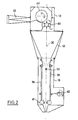
- This hopper also called “metering regulating chimney” is also marketed by the company LAROCHE, it is represented in FIG. 2, it has three essential parts, a condenser 13, a constant charge hopper 19 and a delivery system 41. All these elements are represented in a section perpendicular to their largest dimension which is always the same, equal to the width of the carding
- the stream of unbound fibers transported by the line 22 arrives in the enclosure of the condenser 13.
- the mechanical connection between the line 22 and the enclosure is designed so as to allow the latter to move rotating around a vertical axis without disturbing the power supply.
- the rotating perforated cylinder 43 the central part of which is in communication with the atmosphere, sucks the flakes on its wall while the air is evacuated after passing through the perforations.
- a detaching roller with blades 45 pulls the fibers which fall by gravity into the hopper with constant load 19 by passing through the hopper 52 which has the same width as all the other elements of FIG. 2: the width of the carding machine 4.
- the hopper constant load 19 consists essentially of two rectangular plates, a semi-fixed plate 56 and an oscillating plate 58.
- These plates constitute the walls of a reservoir of unbound fibers. Their horizontal dimension is the width of the carding machine 4 and their height is about five times their maximum spacing.
- the constant flow is ensured by the level detector 59.
- the spacing of the plates is adjustable according to the flow.
- the fibers are drawn towards the carding machine by two delivery rollers 41 whose tangential speed is that of the driving rollers 2 and 3 of the carding machine.
- the plate 58 is driven by an oscillating movement thanks to an eccentric 60 which makes it carry out displacements of a few centimeters in the lower part.
- the level in the reservoir is kept constant by regulating the flow rate of the bale opening machine 23 thanks to the indications of the detector 59.
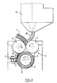
- Figure 3 shows the carding unit 4 according to the invention.
- the two cylinders 2 and 3 rotating in opposite directions of rotation simultaneously drive the continuous mattress of mineral fibers 1 and / or the unbound fibers 18 coming from the flow control hopper 21.
- the function of these two cylinders 2 and 3 is only to regularly lead the materials to the carding machine 4.
- the materials entrained are diverse, they consist of respective proportions of mattress 1 and unbound fibers 18 eminently variable since they can have all the values of the range 0 - 1, from a raw material consisting only of unbound fibers 18 up to a raw material quine comprises that the continuous mattress of mineral fibers 1 without the contribution of any allogenic fiber. But obviously the most common proportions are intermediate between the two extreme values.
- the elements of the carding machine 4 are those described in European patent application EP 371 847.
- the cylindrical brush equipped with fine, long and stiff bristles 6 which carries the materials brought by the rollers 2 and 3.
- the comb 7 with its adjustment system 9 is made of points mounted on the plate 8 which penetrate between the bristles of the brush 5 and extract from it the flakes of fibers which fall naturally towards the elements situated below. It is essentially a hopper 54 fixed to the carding machine. This hopper ends with a rectangular section channel 55.
- the fiber flakes after passing through the channel 55 naturally fall into the receiving enclosure 10, the lower horizontal wall of which is constituted by the conveyor belt 14.
- the device of the invention does not include any suction below the conveyor belt 14 or any other means which would cause the flakes to crush. They are thus allowed, by avoiding any fiber breakage, any additional nesting, any preferential orientation, to keep the properties of the original products.
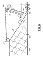
- the enclosure 10 is shown diagrammatically in FIG. 5. Among the other walls, only the rear vertical wall 53 is fixed, the wall situated towards the front is inclined and movable in its plane, it consists of a calendering belt 46 animated of a movement of translation from top to bottom in the plane of the wall.
- This wall is limited by two rollers: an upper fixed motor roller 47 and a free lower roller 49.
- This second roller can be moved along the wall which it tangents so as to produce primitive mattresses 20 of various thicknesses.
- the third roller 48 also free can also see its position vary so as to tension the carpet 46.
- This design of the calender 15 has a double advantage, firstly, the speed of the carpet 46 and that of the conveyor belt 14 can be chosen exactly identical which allows the fibers to be compressed without slipping, thus limiting their degradation. Furthermore the angle of the two belts remains identical which allows the insertion of side walls between them. Laterally, the receiving enclosure 10 is thus limited by two plates 36, 37, which can move so as to materialize the width of the primitive mattress 20.
- the sixth wall of the receiving enclosure 10 is constituted by the bottom of the carding unit composed of the carding machine 4 surmounting the hopper 54 and its channel 55. This bottom serves as a cover for the receiving enclosure 10.
- Figures 6, 7 and 8 show the details of the mechanical systems which constitute an embodiment of the invention.
- Figure 6 first of all, there is shown the front part of the reception enclosure. We see how the movement of the roller 49 along the wall inclined, allows the thickness of the original mattress 20 to be varied from h 1 , maximum thickness to h 2 , minimum thickness.
- the third roller 48 is moved by rotating the arms 51 which carry it around their common axis 50.
- Figure 7 shows the upper part of the receiving enclosure.
- the upper wall 34 is shown insulated and the structural elements which support it are not shown. on the drawing. This wall must be capable of supporting the whole of the hopper 54, of the carding machine 4 as well as the feeding system of the carding machine. Only the hopper 54 is shown in the figure.
- the plate 34 is pierced with a circular hole 35.
- the carding unit 4, hopper 54 and rectangular section channel 55 rests on a circular plate 31 with a diameter greater than that of the hole 35.
- This plate can rotate around the axis vertical 30 by means of rotating rotation shown schematically by the rollers 32.
- the channel 55 is provided at its end with a sheet in which it opens. This has the form of a disc 33 which substantially seals the hole 35.
- the width of the primitive mattress produced by the installation is at its maximum. By rotating the assembly, including the circular plate 31 around the axis 30, more or less wide widths are obtained.
- the plate 36 is generally vertical, parallel to the wall 40. It rests on the ground by pebbles not shown which are guided in grooves so that the plate 36 can move in a direction which is perpendicular to it as well as to the wall 40.
- Rods 38 four in number at two different levels are linked in pairs by rods such as 42. Cylinders 44 make it possible to deform the parallelogram formed by the rod 42, the wall which is parallel to it and the two rods 38. During this deformation, the ends of the rods 38 slide in housings 39 and the plate 36 approaches or moves away of the wall 40 in the direction in which the jack 44 acts.
- each of the plates 36, 37 can be inclined around a vertical axis and / or a horizontal axis to also allow a concentration of the flakes of fibers on the edges.
- FIG. 9 shows the preferred form of an element of the device of the invention, it is the receiving enclosure 10 and the end of the rectangular section channel 55.
- FIG. 9 is a top view of the device.
- the channel 55 instead of ending at the level of the plate 33 is extended on two of its adjacent sides 61 and 62. These sides extend to the vicinity of the conveyor belt 14 and form the rear wall of the receiving enclosure 10 instead of the fixed wall 53 of FIG. 5.
- the wall 61 comes at 63 and the wall 62, at 64.
- the walls 36, 37 are permanently supported on the free ends 65 and 66 of the walls 61 and 62.
- the density correction of the mattress on its edges is obtained here by tightening the downstream ends of the plates 36, 37.
- Continuous mineral fiber mattresses produced on an industrial line may contain a certain proportion of recycled fibers, generally from scrap or defective products.
- a glass fiber mat was available with a density of 10 kg / m 3 and a proportion of recycled fibers of 17%,
- a reconstituted product was thus obtained comprising 40% of recycled fibers, which makes it possible to keep a relatively low production cost while keeping performance little different from that of a product which would be made entirely of new fibers.
- the carding machine which we have has a useful width of 120 cm, however we wish to directly produce a primitive mattress 20 with a usable width of 90 cm.
- the spacing of the two side plates 36 and 37 is adapted to obtain a constant thickness in the enclosure 10.
- the primitive mattress itself, it is here 70% of insulating glass fibers for 30% of large textile glass fiber yarns. length which give the product great elasticity. These threads consist of scraps from the workshop of a plastic processor, a large user of textile fiberglass mats. Here the other fibers all come from the continuous mattress of mineral fibers. As the proportion of flakes of loose fibers is relatively low, the plates 56, 58 of the regulating chimney 19 are tightened to obtain the desired flow rate (the speed of the conveyor belt 26 of the bale opener 23 is adjusted accordingly to avoid too much excess fiber at the entrance to the chimney 19). With the previous settings, a primitive mattress is obtained which has a width (90 cm) which provides the maximum operating efficiency at the final transformer which presses the primitive units to produce the covering panels for the automobile hoods.
Landscapes
- Engineering & Computer Science (AREA)
- Textile Engineering (AREA)
- Chemical & Material Sciences (AREA)
- Inorganic Chemistry (AREA)
- Preliminary Treatment Of Fibers (AREA)
- Nonwoven Fabrics (AREA)
- Paper (AREA)
Claims (7)
- Verfahren zur Herstellung eines Ausgangsvlieses, bestehend aus Faserbündeln und einem nachträglich reaktivierbaren Bindemittel, wobei die Faserbündel durch Zerkleinerung eines Mineralwollefilzes hergestellt sind, dadurch gekennzeichnet, daß man den Faserbündeln ungebundene mineralische oder organische Fasern (18) beimengt, daß man einen ungeordneten Faserflockenteppich (57) in einem Aufnahmebehälter (10) ausschließlich durch die Wirkung der Gravitation bildet und daß man die Breite des Ausgangsvlieses (20) durch die Rotation eines Verteilerkanales (55) um eine im wesentlichen vertikale Achse (30) variiert.
- Verfahren zur Herstellung eines Ausgangsvlieses nach Anspruch 1, dadurch gekennzeichnet, daß die Dicke des ungeordneten Bündelteppichs (57) an den Rändern durch den Versatz seitlicher Platten (36, 37) des Aufnahmebehälters (10) eingestellt ist.
- Verfahren zur Herstellung eines Ausgangsvlieses nach anspruch 1, dadurch gekennzeichnet, daß die nichtgebundenen Fasern sukzessiv durch einen Ballenöffner (23) und durch einen Trichter mit konstanter Ladung (19) behandelt werden, bevor sie einer Kardierungsbehandlung in einer Kardierungseinheit (4) unterzogen werden.
- Vorrichtung zur Variation der Breite eines Ausgangsvlieses (20) aus Faserflocken, die mit einem nachträglich reaktivierbaren Bindemittel vermischt sind, mit einer Kardierungseinheit einschließlich einer Karde (4), an der ein Trichter (54) befestigt ist, der in einem Verteilerkanal (55) endet, wobei die Anordnung darüber hinaus einen Aufnahmebehälter (10) umfaßt, dadurch gekennzeichnet, daß der Verteilerkanal (55) mit Rotationseinrichtungen (31, 32, 33) um eine im wesentlichen vertikale Achse (30) versehen ist.
- Vorrichtung nach Anspruch 4, dadurch gekennnzeichnet, daß der Aufnahmebehälter (10) seitliche Platten (36, 37) mit Einstellvorrichtungen (38, 39, 42, 44) umfaßt, die deren seitlichen Versatz erlauben.
- Vorrichtung nach Anspruch 5, dadurch gekennzeichnet, daß der Aufnahmebehälter (10) mit einer vertikalen Rückwand versehen ist, die eine Verlängerung der oberhalb angeordneten Wand (61, 63) und der angrenzenden Wand (62, 64) des Kanales mit rechteckigem Querschnitt (55) ist, und dadurch, daß die seitlichen Platten (36, 37) sich auf den äußeren Kanten (65, 66) der Wände (61, 62, 63, 64) stützen.
- Vorrichtung nach Anspruch 6, dadurch gekennzeichnet, daß der Aufnahmebehälter (10) mit einem Rollteppich (46) versehen ist, dessen Ebene feststeht.
Applications Claiming Priority (2)
| Application Number | Priority Date | Filing Date | Title |
|---|---|---|---|
| FR9015279 | 1990-12-06 | ||
| FR9015279A FR2670220A1 (fr) | 1990-12-06 | 1990-12-06 | Matelas fibreux destine au pressage. |
Publications (2)
| Publication Number | Publication Date |
|---|---|
| EP0489639A1 EP0489639A1 (de) | 1992-06-10 |
| EP0489639B1 true EP0489639B1 (de) | 1997-02-26 |
Family
ID=9402962
Family Applications (1)
| Application Number | Title | Priority Date | Filing Date |
|---|---|---|---|
| EP91403262A Expired - Lifetime EP0489639B1 (de) | 1990-12-06 | 1991-12-03 | Fasermatte für Pressteile |
Country Status (13)
| Country | Link |
|---|---|
| EP (1) | EP0489639B1 (de) |
| JP (1) | JPH04316652A (de) |
| KR (1) | KR920012595A (de) |
| AR (1) | AR245792A1 (de) |
| AT (1) | ATE149217T1 (de) |
| AU (1) | AU644911B2 (de) |
| CA (1) | CA2057141A1 (de) |
| DE (1) | DE69124783D1 (de) |
| FI (1) | FI915712A7 (de) |
| FR (1) | FR2670220A1 (de) |
| NO (1) | NO178507C (de) |
| NZ (1) | NZ240710A (de) |
| ZA (1) | ZA919599B (de) |
Families Citing this family (3)
| Publication number | Priority date | Publication date | Assignee | Title |
|---|---|---|---|---|
| DE4230356C2 (de) * | 1992-09-10 | 1998-02-12 | Heraklith Holding Ag | Verfahren und Vorrichtung zum Herstellen einer Dämmplatte aus faserigen Materialien mit niedriger Rohdichte, sowie damit hergestellte Dämmplatte |
| US5879802A (en) * | 1996-09-12 | 1999-03-09 | Prince Corporation | Vehicle panel material |
| DE102020102541A1 (de) * | 2020-01-31 | 2021-08-19 | Dieffenbacher GmbH Maschinen- und Anlagenbau | Mischvorrichtung zur Erzeugung einer Mischung aus Mineralfasern und Bindemitteln, Anlage zur Erzeugung einer Mineralfasermatte und Verfahren zur Erzeugung einer Mischung aus Mineralfasern und Bindemitteln |
Family Cites Families (6)
| Publication number | Priority date | Publication date | Assignee | Title |
|---|---|---|---|---|
| DE1021781B (de) * | 1957-03-15 | 1957-12-27 | Gruenzweig & Hartmann A G | Verfahren und Vorrichtung zum kontinuierlichen Aufbereiten von Abfaellen aus der Mineralwolle-Herstellung |
| US3004878A (en) * | 1957-08-16 | 1961-10-17 | Owens Corning Fiberglass Corp | Method of producing fibrous glass building boards and product |
| US3908591A (en) * | 1974-04-29 | 1975-09-30 | Owens Corning Fiberglass Corp | Apparatus for treating sheet material |
| US4097209A (en) * | 1977-03-23 | 1978-06-27 | Armstrong Cork Company | Apparatus for forming a mineral wool fiberboard product |
| FR2529917A1 (fr) * | 1982-07-06 | 1984-01-13 | Saint Gobain Isover | Procede et dispositif pour la formation de feutre de fibres contenant un produit additionnel |
| FR2639868B1 (fr) * | 1988-12-01 | 1991-05-31 | Saint Gobain Isover | Materiau composite a base de fibres minerales. dispositif d'obtention et application du materiau composite |
-
1990
- 1990-12-06 FR FR9015279A patent/FR2670220A1/fr not_active Withdrawn
-
1991
- 1991-11-13 AU AU87804/91A patent/AU644911B2/en not_active Ceased
- 1991-11-25 NZ NZ240710A patent/NZ240710A/en unknown
- 1991-12-03 AR AR91321296A patent/AR245792A1/es active
- 1991-12-03 AT AT91403262T patent/ATE149217T1/de not_active IP Right Cessation
- 1991-12-03 EP EP91403262A patent/EP0489639B1/de not_active Expired - Lifetime
- 1991-12-03 DE DE69124783T patent/DE69124783D1/de not_active Expired - Lifetime
- 1991-12-04 FI FI915712A patent/FI915712A7/fi not_active Application Discontinuation
- 1991-12-05 KR KR1019910022263A patent/KR920012595A/ko not_active Withdrawn
- 1991-12-05 NO NO914790A patent/NO178507C/no unknown
- 1991-12-05 ZA ZA919599A patent/ZA919599B/xx unknown
- 1991-12-05 CA CA002057141A patent/CA2057141A1/fr not_active Abandoned
- 1991-12-06 JP JP3323242A patent/JPH04316652A/ja active Pending
Also Published As
| Publication number | Publication date |
|---|---|
| ZA919599B (en) | 1992-09-30 |
| NO914790L (no) | 1992-06-09 |
| EP0489639A1 (de) | 1992-06-10 |
| ATE149217T1 (de) | 1997-03-15 |
| AR245792A1 (es) | 1994-02-28 |
| FI915712A0 (fi) | 1991-12-04 |
| JPH04316652A (ja) | 1992-11-09 |
| NZ240710A (en) | 1994-05-26 |
| KR920012595A (ko) | 1992-07-27 |
| NO178507C (no) | 1996-04-10 |
| FI915712L (fi) | 1992-06-07 |
| NO178507B (no) | 1996-01-02 |
| DE69124783D1 (de) | 1997-04-03 |
| AU644911B2 (en) | 1993-12-23 |
| CA2057141A1 (fr) | 1992-06-07 |
| FR2670220A1 (fr) | 1992-06-12 |
| FI915712A7 (fi) | 1992-06-07 |
| NO914790D0 (no) | 1991-12-05 |
| AU8780491A (en) | 1992-06-11 |
Similar Documents
| Publication | Publication Date | Title |
|---|---|---|
| EP1397549B1 (de) | Federfüllung, verfahren und vorrichtung | |
| EP2013128B1 (de) | Verfahren zum herstellen eines dreidimensionalen faservlieses, vorrichtung und faservlies | |
| CA2215491C (fr) | Procede et dispositif de fabrication d'un materiau composite | |
| CA2407075C (fr) | Procede et dispositif de fabrication d'un profile composite forme de matiere organique thermoplastique renforcee par des fibres de renforcement | |
| EP3446868A1 (de) | Neues zwischenmaterial von konstanter breite für die herstellung von verbundwerkstücken über direktverfahren | |
| EP2776617B1 (de) | Verfahren zur herstellung einer kontinuierlichen faserbahn mit langen naturfasern und zugehörige vorrichtung sowie faserbahn | |
| CH653605A5 (fr) | Procede de fabrication en continu de produits a base de matiere thermoplastique, installation pour la mise en oeuvre de ce procede et produits obtenus par ce procede. | |
| FR2768440A1 (fr) | Dispositif pour la production d'une nappe de fibres | |
| EP0960227B1 (de) | Verfahren und vorrichtung zur herstellung von textilen produkten und erhaltene textile produkte | |
| EP0888471A1 (de) | Verfahren und vorrichtung zur herstellung von verbundplatten | |
| EP1226298B1 (de) | Verfahren und vorrichtung zur herstellung von verbundplatten | |
| BE897526A (fr) | Plaque de construction, dispositif et procèdè pour sa formation. | |
| EP1900863A1 (de) | Verfahren und Anlage zum Herstellen eines textilen Gebilde mit Zwischenlagen und Vorrichtung | |
| EP0489639A1 (de) | Fasermatte für Pressteile | |
| EP1300492B1 (de) | Verfahren und Anlage zur Herstellung eines verdichteten Vliesstoffes und Vorrichtung zur Verdichtung eines Vliesstoffes | |
| EP0371847A1 (de) | Verbundmaterial aus Mineralfasern, Anlage für die Erzeugung und Verwendung des Verbundmaterials | |
| FR2531662A1 (fr) | Plaque de construction, dispositif et procede pour sa formation | |
| EP3212829B1 (de) | Verfahren und vorrichtung zur entwebung und neuausrichtung von kohlenstofffasern | |
| EP3908687B1 (de) | Einheit und verfahren zur herstellung von vliesstoffen | |
| WO1998036114A1 (fr) | Procede de recyclage de revetements de sol ou muraux textiles et nappes fibreuses obtenues par la mise en oeuvre de ce procede | |
| FR2658208A1 (de) | ||
| BE894826A (fr) | Procede et appareil pour la fabrication de torons coupes et comprimes | |
| FR3120372A1 (fr) | Installation de fabrication de laine minerale | |
| FR2874388A1 (fr) | Rouleau pour une machine de traitement de fibres | |
| FR3083806A1 (fr) | Procede de formation d'une couche fibreuse pour une piece d'equipement de vehicule automobile, installation et piece d'equipement associees |
Legal Events
| Date | Code | Title | Description |
|---|---|---|---|
| PUAI | Public reference made under article 153(3) epc to a published international application that has entered the european phase |
Free format text: ORIGINAL CODE: 0009012 |
|
| AK | Designated contracting states |
Kind code of ref document: A1 Designated state(s): AT BE CH DE DK ES FR GB IT LI LU NL SE |
|
| 17P | Request for examination filed |
Effective date: 19920703 |
|
| 17Q | First examination report despatched |
Effective date: 19941013 |
|
| GRAG | Despatch of communication of intention to grant |
Free format text: ORIGINAL CODE: EPIDOS AGRA |
|
| GRAH | Despatch of communication of intention to grant a patent |
Free format text: ORIGINAL CODE: EPIDOS IGRA |
|
| GRAH | Despatch of communication of intention to grant a patent |
Free format text: ORIGINAL CODE: EPIDOS IGRA |
|
| GRAA | (expected) grant |
Free format text: ORIGINAL CODE: 0009210 |
|
| AK | Designated contracting states |
Kind code of ref document: B1 Designated state(s): AT BE CH DE DK ES FR GB IT LI LU NL SE |
|
| PG25 | Lapsed in a contracting state [announced via postgrant information from national office to epo] |
Ref country code: IT Free format text: LAPSE BECAUSE OF FAILURE TO SUBMIT A TRANSLATION OF THE DESCRIPTION OR TO PAY THE FEE WITHIN THE PRE;WARNING: LAPSES OF ITALIAN PATENTS WITH EFFECTIVE DATE BEFORE 2007 MAY HAVE OCCURRED AT ANY TIME BEFORE 2007. THE CORRECT EFFECTIVE DATE MAY BE DIFFERENT FROM THE ONE RECORDED.SCRIBED TIME-LIMIT Effective date: 19970226 Ref country code: GB Effective date: 19970226 Ref country code: NL Free format text: LAPSE BECAUSE OF FAILURE TO SUBMIT A TRANSLATION OF THE DESCRIPTION OR TO PAY THE FEE WITHIN THE PRESCRIBED TIME-LIMIT Effective date: 19970226 Ref country code: ES Free format text: THE PATENT HAS BEEN ANNULLED BY A DECISION OF A NATIONAL AUTHORITY Effective date: 19970226 Ref country code: FR Free format text: THE PATENT HAS BEEN ANNULLED BY A DECISION OF A NATIONAL AUTHORITY Effective date: 19970226 Ref country code: DK Effective date: 19970226 Ref country code: AT Effective date: 19970226 |
|
| REF | Corresponds to: |
Ref document number: 149217 Country of ref document: AT Date of ref document: 19970315 Kind code of ref document: T |
|
| REG | Reference to a national code |
Ref country code: CH Ref legal event code: EP |
|
| REF | Corresponds to: |
Ref document number: 69124783 Country of ref document: DE Date of ref document: 19970403 |
|
| PG25 | Lapsed in a contracting state [announced via postgrant information from national office to epo] |
Ref country code: SE Effective date: 19970526 |
|
| PG25 | Lapsed in a contracting state [announced via postgrant information from national office to epo] |
Ref country code: DE Effective date: 19970527 |
|
| NLV1 | Nl: lapsed or annulled due to failure to fulfill the requirements of art. 29p and 29m of the patents act | ||
| GBV | Gb: ep patent (uk) treated as always having been void in accordance with gb section 77(7)/1977 [no translation filed] |
Effective date: 19970226 |
|
| PG25 | Lapsed in a contracting state [announced via postgrant information from national office to epo] |
Ref country code: LU Free format text: LAPSE BECAUSE OF NON-PAYMENT OF DUE FEES Effective date: 19971203 |
|
| PLBE | No opposition filed within time limit |
Free format text: ORIGINAL CODE: 0009261 |
|
| STAA | Information on the status of an ep patent application or granted ep patent |
Free format text: STATUS: NO OPPOSITION FILED WITHIN TIME LIMIT |
|
| PG25 | Lapsed in a contracting state [announced via postgrant information from national office to epo] |
Ref country code: LI Free format text: LAPSE BECAUSE OF NON-PAYMENT OF DUE FEES Effective date: 19971231 Ref country code: BE Free format text: LAPSE BECAUSE OF NON-PAYMENT OF DUE FEES Effective date: 19971231 Ref country code: CH Free format text: LAPSE BECAUSE OF NON-PAYMENT OF DUE FEES Effective date: 19971231 |
|
| 26N | No opposition filed | ||
| BERE | Be: lapsed |
Owner name: ISOVER SAINT-GOBAIN Effective date: 19971231 |
|
| REG | Reference to a national code |
Ref country code: CH Ref legal event code: PL |
|
| REG | Reference to a national code |
Ref country code: FR Ref legal event code: ST |