EP0497377B1 - Générateur de fréquence pour un verrouillage de synchronisation - Google Patents
Générateur de fréquence pour un verrouillage de synchronisation Download PDFInfo
- Publication number
- EP0497377B1 EP0497377B1 EP92101641A EP92101641A EP0497377B1 EP 0497377 B1 EP0497377 B1 EP 0497377B1 EP 92101641 A EP92101641 A EP 92101641A EP 92101641 A EP92101641 A EP 92101641A EP 0497377 B1 EP0497377 B1 EP 0497377B1
- Authority
- EP
- European Patent Office
- Prior art keywords
- dependent
- phase
- independent
- locked loop
- signal
- Prior art date
- Legal status (The legal status is an assumption and is not a legal conclusion. Google has not performed a legal analysis and makes no representation as to the accuracy of the status listed.)
- Expired - Lifetime
Links
- 230000001419 dependent effect Effects 0.000 claims description 97
- 238000000034 method Methods 0.000 claims description 13
- 238000012544 monitoring process Methods 0.000 claims description 4
- 238000001514 detection method Methods 0.000 claims description 3
- 230000000694 effects Effects 0.000 description 9
- 238000010586 diagram Methods 0.000 description 6
- 239000002131 composite material Substances 0.000 description 5
- 230000001360 synchronised effect Effects 0.000 description 5
- 230000015572 biosynthetic process Effects 0.000 description 4
- 230000007246 mechanism Effects 0.000 description 4
- 238000003786 synthesis reaction Methods 0.000 description 4
- 230000008901 benefit Effects 0.000 description 2
- 230000001427 coherent effect Effects 0.000 description 2
- 230000006870 function Effects 0.000 description 2
- 230000008569 process Effects 0.000 description 2
- 230000007704 transition Effects 0.000 description 2
- 230000001934 delay Effects 0.000 description 1
- 230000000873 masking effect Effects 0.000 description 1
- 230000002194 synthesizing effect Effects 0.000 description 1
Images


Classifications
-
- G—PHYSICS
- G09—EDUCATION; CRYPTOGRAPHY; DISPLAY; ADVERTISING; SEALS
- G09G—ARRANGEMENTS OR CIRCUITS FOR CONTROL OF INDICATING DEVICES USING STATIC MEANS TO PRESENT VARIABLE INFORMATION
- G09G5/00—Control arrangements or circuits for visual indicators common to cathode-ray tube indicators and other visual indicators
- G09G5/12—Synchronisation between the display unit and other units, e.g. other display units, video-disc players
-
- H—ELECTRICITY
- H04—ELECTRIC COMMUNICATION TECHNIQUE
- H04N—PICTORIAL COMMUNICATION, e.g. TELEVISION
- H04N5/00—Details of television systems
- H04N5/04—Synchronising
- H04N5/06—Generation of synchronising signals
- H04N5/067—Arrangements or circuits at the transmitter end
- H04N5/073—Arrangements or circuits at the transmitter end for mutually locking plural sources of synchronising signals, e.g. studios or relay stations
-
- G—PHYSICS
- G09—EDUCATION; CRYPTOGRAPHY; DISPLAY; ADVERTISING; SEALS
- G09G—ARRANGEMENTS OR CIRCUITS FOR CONTROL OF INDICATING DEVICES USING STATIC MEANS TO PRESENT VARIABLE INFORMATION
- G09G2340/00—Aspects of display data processing
- G09G2340/12—Overlay of images, i.e. displayed pixel being the result of switching between the corresponding input pixels
- G09G2340/125—Overlay of images, i.e. displayed pixel being the result of switching between the corresponding input pixels wherein one of the images is motion video
Definitions
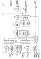
- the horizontal scan rate of the graphics controller 150 is matched to that of the incoming independent video signal 120, whatever its source, and is synchronized such that the horizontal scans of each video source start at the same time.
- stability of the phase locked loop would affect the stability of the dependent video image relative to the independent video image. That is, if there is any significant jitter in the phase-locked loop, there would be a corresponding visible jitter in the dependent video's image when overlaid on the independent video.
- the two inputs are monitored by VSYNC comparator 216, and if a leading edge of dependent HSYNC signal 245 is detected in between the leading edges of the output of digital delay 210 and dependent VSYNC signal 260, then an output signal 280 (Vertical Reset) is generated indicating that the genlock system is out of vertical synchronization.
- this signal would be used as an interrupt signal to an external processor system (not shown) controlling the dependent video source, which would then reset the vertical line controls therein, effectively placing the genlock system into vertical synchronization.
- the VSYNC comparator 216 will only generate the vertical reset signal 280 if the genlock system is out of vertical synchronization. This signal will not be generated after vertical synchronization has been established.
Landscapes
- Engineering & Computer Science (AREA)
- Multimedia (AREA)
- Physics & Mathematics (AREA)
- Computer Hardware Design (AREA)
- General Physics & Mathematics (AREA)
- Theoretical Computer Science (AREA)
- Signal Processing (AREA)
- Synchronizing For Television (AREA)
- Processing Of Color Television Signals (AREA)
- Controls And Circuits For Display Device (AREA)
Claims (13)
- Dispositif de génération de fréquence à verrouillage de générateur comprenant :
une boucle à verrouillage de phase (202, 208, 218, 220, 226, 230, 234) recevant en tant qu'entrée, et synchronisant un signal de synchronisation horizontale dépendant (245) d'une source vidéo dépendante avec le signal de synchronisation horizontale indépendant (240) d'une source vidéo indépendante, et présentant une fréquence de sortie, dans lequel le cadencement de ladite source vidéo dépendante est commandé soit directement, soit indirectement par la fréquence de sortie de ladite boucle à verrouillage de phase, caractérisé par :un moyen (204) destiné à retarder l'un des signaux de synchronisation horizontale indépendant ou dépendant (240, 245) d'un intervalle de temps prévisible avant leur application à ladite boucle à verrouillage de phase dans le but d'établir une différence de temps connue entre les signaux de synchronisation horizontale indépendant et dépendant (240, 245),un moyen de commutateur d'entrée (212, 214) destiné à commuter les entrées vers ladite boucle à verrouillage de phase de sorte qu'en mode de fonctionnement normal, les signaux de synchronisation horizontale indépendant et dépendant (240, 245) soient entrés dans la boucle à verrouillage de phase, et de sorte que dans un mode de fonctionnement par défaut un sous-multiple de la fréquence de sortie de la boucle à verrouillage de phase et un signal de fréquence de référence fixe soit appliqué à l'entrée de la boucle à verrouillage de phase, de sorte que dans le mode de fonctionnement par défaut, la boucle à verrouillage de phase établit un nouveau point de fonctionnement stable sur la base du signal de fréquence de référence,un moyen de détection de synchronisation (206) destiné à détecter la présence et la cadence des signaux de synchronisation horizontale indépendant et dépendant sur la base des contraintes de cadencement préétablies, et destiné à procurer une sortie lorsque les signaux de synchronisation horizontale ne sont pas présents ou tombent à l'extérieur d'une plage établie telle que définie par lesdites contraintes de cadencement préétablies, etun moyen (206A, 206B) destiné à commander le commutateur d'entrée de boucle à verrouillage de phase sur la base de la sortie du moyen de détection de synchronisation (206) de sorte que si les signaux de synchronisation horizontale ne sont pas détectés d'une façon telle qu'ils tombent à l'intérieur desdites contraintes de cadencement préétablies, ledit commutateur d'entrée de boucle à verrouillage de phase (212, 214) sera établi de telle façon que ledit signal de fréquence de référence et ledit sous-multiple de la fréquence de sortie de la boucle à verrouillage de phase soient appliqués en tant qu'entrées à la boucle à verrouillage de phase. - Dispositif selon la revendication 1, comprenant en outre :
un moyen (216) destiné à déterminer et à indiquer le synchronisme d'un signal de synchronisation verticale (260) d'une source vidéo dépendante et d'un signal de synchronisation verticale (255) d'une source vidéo indépendante en déterminant qu'un signal de synchronisation horizontale provenant de l'une ou l'autre de la source vidéo indépendante, de la source vidéo dépendante, ou des deux, n'apparait pas entre des occurrences successives des signaux de synchronisation verticale de la source vidéo dépendante. - Dispositif selon la revendication 2, comprenant en outre :
un moyen (210) destiné à retarder l'un desdits signaux de synchronisation verticale (255, 260) d'un intervalle de temps prévisible avant son application auxdits moyens de détermination de synchronisme vertical (216) dans le but d'établir un décalage de temps connu entre les deux signaux de synchronisation verticale. - Dispositif selon la revendication 3,
dans lequel une ou plusieurs desdites valeurs de retard de temps sont réglables. - Dispositif selon l'une quelconque des revendications précédentes comprenant en outre,
un moyen (222, 224, 228) destiné à établir et à générer un signal de commande de commutateur de trame (275) correspondant à une zone rectangulaire complètement contenue à l'intérieur de la trame de la source vidéo indépendante, par une quantité commandée de différence de temps entre les signaux de synchronisation horizontale et verticale desdites sources vidéo indépendante et dépendante, et par un comptage de lignes verticales et un comptage de positions horizontales établis de sorte que le signal de synchronisation horizontale dépendant définit le bord gauche de ladite zone rectangulaire, le comptage des positions horizontales établit le bord droit en définissant une limite pour la quantité de balayage horizontal après le bord gauche, qui sera appliquée à ladite zone rectangulaire, le signal de synchronisation verticale dépendant établit le bord supérieur de ladite zone rectangulaire, et le comptage des lignes verticales établit le bord inférieur de ladite zone rectangulaire en établissant le nombre de lignes de balayage après le bord supérieur qui sera appliqué à ladite zone rectangulaire. - Dispositif selon l'une quelconque des revendications précédentes comprenant en outre :
un moyen (234) destiné à déterminer que la boucle à verrouillage de phase est dans une condition verrouillée stable. - Dispositif selon la revendication 5 ou 6, comprenant en outre :
un moyen (232) destiné à retarder ledit signal de commande de commutateur de trame d'un intervalle de temps prévisible. - Dispositif selon l'une quelconque des revendications précédentes, comprenant en outre :un diviseur numérique programmable (202) établissant le sous-multiple de la fréquence de sortie de la boucle à verrouillage de phase, etun diviseur numérique programmable (208) en série avec le signal de fréquence de référence.
- Procédé de synchronisation d'une source vidéo dépendante avec une source vidéo indépendante, comprenant :
la fourniture de signaux de synchronisation horizontale à partir d'une source vidéo indépendante et d'une source vidéo dépendante aux entrées d'une boucle à verrouillage de phase, ladite boucle à verrouillage de phase comprenant un oscillateur commandé en tension générant une sortie, caractérisé par les étapes consistant à :procurer des signaux de synchronisation verticale depuis la source vidéo indépendante et la source vidéo dépendante,déphaser l'un des signaux de synchronisation horizontale afin de créer un décalage horizontal de la source vidéo dépendante dans une présentation vidéo des deux sources vidéo, etdéphaser un des signaux de synchronisation verticale correspondant afin de créer un décalage vertical de la source vidéo dépendante dans la présentation vidéo des deux sources vidéo,surveiller la présence et la cadence des signaux de synchronisation horizontale, etappliquer, dans un mode de fonctionnement par défaut, un sous-multiple de la fréquence de sortie de l'oscillateur commandé en tension et un siqnal de référence de fréquence fixe aux entrées de la boucle à verrouillage de phase dans le cas où l'un ou l'autre des signaux de synchronisation horizontale n'est pas présent ou tombe à l'extérieur des limites de cadences prescrites. - Procédé selon la revendication 9, comprenant en outre :
le recouvrement de l'image vidéo dépendante à l'intérieur de l'image vidéo indépendante afin de révéler l'image vidéo indépendante dans une partie de l'image vidéo dépendante. - Procédé selon la revendication 10,
dans lequel des codages de texte et de chrominance sont appliqués dans la partie de l'image vidéo dépendante. - Procédé selon l'une quelconque des revendications 9 à 11, comprenant en outre :la surveillance du verrouillage de la boucle à verrouillage de phase, etl'interruption de la source vidéo dépendante sur la base de la perte de verrouillage.
- Procédé selon la revendication 12, comprenant en outre :la poursuite de la surveillance de la présence et de la cadence des signaux de synchronisation horizontale dans le mode par défaut, etla détermination de ce qu'un retour au verrouillage dans la boucle à verrouillage de phase est dû, soit au rétablissement d'un signal de synchronisation horizontale manquant ou erroné, soit au verrouillage de phase dans le mode par défaut.
Applications Claiming Priority (2)
| Application Number | Priority Date | Filing Date | Title |
|---|---|---|---|
| US649033 | 1991-01-31 | ||
| US07/649,033 US5155595A (en) | 1991-01-31 | 1991-01-31 | Genlock frequency generator |
Publications (3)
| Publication Number | Publication Date |
|---|---|
| EP0497377A2 EP0497377A2 (fr) | 1992-08-05 |
| EP0497377A3 EP0497377A3 (en) | 1992-10-07 |
| EP0497377B1 true EP0497377B1 (fr) | 1997-03-26 |
Family
ID=24603204
Family Applications (1)
| Application Number | Title | Priority Date | Filing Date |
|---|---|---|---|
| EP92101641A Expired - Lifetime EP0497377B1 (fr) | 1991-01-31 | 1992-01-31 | Générateur de fréquence pour un verrouillage de synchronisation |
Country Status (4)
| Country | Link |
|---|---|
| US (1) | US5155595A (fr) |
| EP (1) | EP0497377B1 (fr) |
| JP (1) | JPH04343392A (fr) |
| DE (1) | DE69218476T2 (fr) |
Cited By (1)
| Publication number | Priority date | Publication date | Assignee | Title |
|---|---|---|---|---|
| US8797334B2 (en) | 2010-01-06 | 2014-08-05 | Apple Inc. | Facilitating efficient switching between graphics-processing units |
Families Citing this family (32)
| Publication number | Priority date | Publication date | Assignee | Title |
|---|---|---|---|---|
| JP3347339B2 (ja) * | 1991-04-08 | 2002-11-20 | キヤノン株式会社 | 画像処理装置 |
| US5404393A (en) * | 1991-10-03 | 1995-04-04 | Viscorp | Method and apparatus for interactive television through use of menu windows |
| AU666185B2 (en) * | 1992-04-29 | 1996-02-01 | Canon Kabushiki Kaisha | A portable video animation device |
| JP3293946B2 (ja) * | 1992-04-29 | 2002-06-17 | キヤノン インフォメーション システムズ リサーチ オーストラリア プロプライエタリー リミテツド | 画像処理装置 |
| US5394171A (en) * | 1992-11-02 | 1995-02-28 | Zenith Electronics Corp. | Synchronizing signal front end processor for video monitor |
| JPH06189194A (ja) * | 1992-12-17 | 1994-07-08 | Pioneer Electron Corp | 映像合成装置 |
| CA2163861A1 (fr) * | 1994-03-28 | 1995-10-05 | Jimmie D. Songer | Dispositif de visualisation en deux et trois dimensions |
| US6014125A (en) * | 1994-12-08 | 2000-01-11 | Hyundai Electronics America | Image processing apparatus including horizontal and vertical scaling for a computer display |
| US5621428A (en) * | 1994-12-12 | 1997-04-15 | Auravision Corporation | Automatic alignment of video window on a multimedia screen |
| US5835134A (en) * | 1995-10-13 | 1998-11-10 | Digital Equipment Corporation | Calibration and merging unit for video adapters |
| EP0842583B1 (fr) * | 1996-06-06 | 2002-05-02 | Koninklijke Philips Electronics N.V. | Extraction de la synchronisation horizontale |
| EP0920194A4 (fr) * | 1996-08-13 | 2000-11-02 | Fujitsu General Ltd | Circuit avec boucle a phase asservie pour dispositif d'affichage numerique |
| US6441812B1 (en) * | 1997-03-31 | 2002-08-27 | Compaq Information Techniques Group, L.P. | Hardware system for genlocking |
| US5914757A (en) | 1997-04-21 | 1999-06-22 | Philips Electronics North America Corporation | Synchronization of multiple video and graphic sources with a display using a slow PLL approach |
| KR100275753B1 (ko) * | 1998-11-30 | 2000-12-15 | 윤종용 | 텔레비젼 시스템의 지터 보정장치 및 방법 |
| US6292225B1 (en) * | 1999-05-07 | 2001-09-18 | Sony Corporation | Precision horizontal positioning system |
| US6999131B2 (en) * | 2000-02-23 | 2006-02-14 | Matsushita Electric Industrial Co., Ltd. | Video output apparatus and output video changeover control method |
| US6507370B1 (en) | 2000-03-20 | 2003-01-14 | International Business Machines Corporation | Highly adjustable video composite sync separator and variable gain pixel clock frequency locking apparatus and method |
| GB2415852B (en) * | 2004-07-02 | 2010-07-14 | Filmlight Ltd | Method and apparatus for image processing |
| KR100663647B1 (ko) * | 2005-06-01 | 2007-01-03 | 삼성전자주식회사 | 디스플레이장치 및 그 제어방법 |
| US8994700B2 (en) * | 2006-03-23 | 2015-03-31 | Mark J. Foster | Artifact-free transitions between dual display controllers |
| US8681159B2 (en) * | 2006-08-04 | 2014-03-25 | Apple Inc. | Method and apparatus for switching between graphics sources |
| US8170013B2 (en) * | 2007-06-12 | 2012-05-01 | Thomson Licensing | Automatic compensation of a delay of a synchronization signal in a packet switching network |
| US8102470B2 (en) * | 2008-02-22 | 2012-01-24 | Cisco Technology, Inc. | Video synchronization system |
| US8300056B2 (en) | 2008-10-13 | 2012-10-30 | Apple Inc. | Seamless display migration |
| JP5558079B2 (ja) * | 2009-11-06 | 2014-07-23 | 株式会社東芝 | 磁気共鳴画像診断装置 |
| US8368702B2 (en) | 2010-01-06 | 2013-02-05 | Apple Inc. | Policy-based switching between graphics-processing units |
| US8648868B2 (en) | 2010-01-06 | 2014-02-11 | Apple Inc. | Color correction to facilitate switching between graphics-processing units |
| US8730251B2 (en) | 2010-06-07 | 2014-05-20 | Apple Inc. | Switching video streams for a display without a visible interruption |
| US8526609B1 (en) | 2011-06-23 | 2013-09-03 | Bby Solutions, Inc. | Method for real-time compositing of encrypted video streams without decryption |
| US9036084B2 (en) * | 2013-04-11 | 2015-05-19 | Qualcomm Incorporated | Apparatus and method for synchronous display of video data |
| US10484578B2 (en) | 2018-03-30 | 2019-11-19 | Cae Inc. | Synchronizing video outputs towards a single display frequency |
Family Cites Families (11)
| Publication number | Priority date | Publication date | Assignee | Title |
|---|---|---|---|---|
| DE2314289A1 (de) * | 1973-03-22 | 1974-10-10 | Nordmende | Fernsehempfaenger mit mitteln zur ueberwachung eines raumes durch eine fernsehkamera oder einer zweiten sendung |
| DE2614199C3 (de) * | 1976-04-02 | 1982-05-27 | Saba Gmbh, 7730 Villingen-Schwenningen | Fernsehempfänger mit einer Schaltungsanordnung zur gleichzeitigen Wiedergabe mehrerer Programme |
| US4591910A (en) * | 1984-03-14 | 1986-05-27 | Zenith Electronics Corporation | Horizontal picture centering |
| JPS60194679A (ja) * | 1984-03-15 | 1985-10-03 | Sony Corp | テレビジヨン受像機 |
| US4580165A (en) * | 1984-04-12 | 1986-04-01 | General Electric Company | Graphic video overlay system providing stable computer graphics overlayed with video image |
| US4611230A (en) * | 1984-12-18 | 1986-09-09 | Zenith Electronics Corporation | Vertical video centering control system |
| US4639765A (en) * | 1985-02-28 | 1987-01-27 | Texas Instruments Incorporated | Synchronization system for overlay of an internal video signal upon an external video signal |
| US4729024A (en) * | 1985-03-19 | 1988-03-01 | Canon Kabushiki Kaisha | Synchronizing pulse signal generation device |
| US4675736A (en) * | 1985-09-25 | 1987-06-23 | Humphrey Instruments, Inc. | Superimposed analog video image on plotted digital field tester display |
| US4843469A (en) * | 1987-04-13 | 1989-06-27 | The Grass Valley Group, Inc. | Rapid signal acquisition and phase averaged horizontal timing from composite sync |
| JPH02193468A (ja) * | 1989-01-20 | 1990-07-31 | Sanyo Electric Co Ltd | ピクチヤインピクチヤ処理回路 |
-
1991
- 1991-01-31 US US07/649,033 patent/US5155595A/en not_active Expired - Lifetime
-
1992
- 1992-01-31 JP JP4042245A patent/JPH04343392A/ja not_active Withdrawn
- 1992-01-31 DE DE69218476T patent/DE69218476T2/de not_active Expired - Fee Related
- 1992-01-31 EP EP92101641A patent/EP0497377B1/fr not_active Expired - Lifetime
Cited By (1)
| Publication number | Priority date | Publication date | Assignee | Title |
|---|---|---|---|---|
| US8797334B2 (en) | 2010-01-06 | 2014-08-05 | Apple Inc. | Facilitating efficient switching between graphics-processing units |
Also Published As
| Publication number | Publication date |
|---|---|
| EP0497377A2 (fr) | 1992-08-05 |
| EP0497377A3 (en) | 1992-10-07 |
| HK1000485A1 (en) | 1998-03-27 |
| DE69218476T2 (de) | 1997-10-30 |
| US5155595A (en) | 1992-10-13 |
| DE69218476D1 (de) | 1997-04-30 |
| JPH04343392A (ja) | 1992-11-30 |
Similar Documents
| Publication | Publication Date | Title |
|---|---|---|
| US5155595A (en) | Genlock frequency generator | |
| US4962427A (en) | TV receiver including multistandard OSD | |
| US5541666A (en) | Method and apparatus for overlaying digitally generated graphics over an analog video signal | |
| US4580165A (en) | Graphic video overlay system providing stable computer graphics overlayed with video image | |
| US8384707B2 (en) | Method for synchronizing display of images in a multi-display computer system | |
| US4639765A (en) | Synchronization system for overlay of an internal video signal upon an external video signal | |
| JP2004508747A (ja) | 入力ビデオ信号と出力ビデオ信号を垂直にロックさせるための方法および装置 | |
| KR100315246B1 (ko) | 디지털 표시 장치용 위상 동기 루프 회로 | |
| US5146336A (en) | Sync control for video overlay | |
| EP0899717B1 (fr) | Circuit de boucle à verrouillage de phase | |
| HK1000485B (en) | Genlock frequency generator | |
| US5534939A (en) | Digital video clock generation system | |
| JP3085505B2 (ja) | スキュー対応pll回路 | |
| JP2880187B2 (ja) | デジタルテレビジョン受像機 | |
| JP3024724B2 (ja) | スキュー検出回路 | |
| JP2877683B2 (ja) | ビデオカメラの外部同期方法 | |
| JP2661300B2 (ja) | 画像標本化クロックの制御方法 | |
| JPS62114330A (ja) | 位相同期回路 | |
| JPS643252Y2 (fr) | ||
| JPH05252438A (ja) | 映像信号サンプリング制御回路 | |
| KR19990001545A (ko) | 영상처리 시스템에서의 동기신호 발생장치 | |
| JP2001333293A (ja) | 映像表示装置 | |
| JPH04360194A (ja) | 表示メモリ制御装置 | |
| HK1014110B (en) | Method and apparatus for overlaying digitally generated graphics over an analog video signal | |
| JPH06105246A (ja) | デジタル画像生成装置 |
Legal Events
| Date | Code | Title | Description |
|---|---|---|---|
| PUAI | Public reference made under article 153(3) epc to a published international application that has entered the european phase |
Free format text: ORIGINAL CODE: 0009012 |
|
| AK | Designated contracting states |
Kind code of ref document: A2 Designated state(s): DE FR GB IT NL |
|
| PUAL | Search report despatched |
Free format text: ORIGINAL CODE: 0009013 |
|
| AK | Designated contracting states |
Kind code of ref document: A3 Designated state(s): DE FR GB IT NL |
|
| 17P | Request for examination filed |
Effective date: 19930407 |
|
| 17Q | First examination report despatched |
Effective date: 19950227 |
|
| GRAG | Despatch of communication of intention to grant |
Free format text: ORIGINAL CODE: EPIDOS AGRA |
|
| GRAH | Despatch of communication of intention to grant a patent |
Free format text: ORIGINAL CODE: EPIDOS IGRA |
|
| GRAH | Despatch of communication of intention to grant a patent |
Free format text: ORIGINAL CODE: EPIDOS IGRA |
|
| GRAA | (expected) grant |
Free format text: ORIGINAL CODE: 0009210 |
|
| AK | Designated contracting states |
Kind code of ref document: B1 Designated state(s): DE FR GB IT NL |
|
| REF | Corresponds to: |
Ref document number: 69218476 Country of ref document: DE Date of ref document: 19970430 |
|
| ITF | It: translation for a ep patent filed | ||
| ET | Fr: translation filed | ||
| PGFP | Annual fee paid to national office [announced via postgrant information from national office to epo] |
Ref country code: FR Payment date: 19971218 Year of fee payment: 7 |
|
| PGFP | Annual fee paid to national office [announced via postgrant information from national office to epo] |
Ref country code: DE Payment date: 19971222 Year of fee payment: 7 Ref country code: NL Payment date: 19971222 Year of fee payment: 7 |
|
| PLBE | No opposition filed within time limit |
Free format text: ORIGINAL CODE: 0009261 |
|
| STAA | Information on the status of an ep patent application or granted ep patent |
Free format text: STATUS: NO OPPOSITION FILED WITHIN TIME LIMIT |
|
| 26N | No opposition filed | ||
| PG25 | Lapsed in a contracting state [announced via postgrant information from national office to epo] |
Ref country code: NL Free format text: LAPSE BECAUSE OF NON-PAYMENT OF DUE FEES Effective date: 19990801 |
|
| PG25 | Lapsed in a contracting state [announced via postgrant information from national office to epo] |
Ref country code: FR Free format text: LAPSE BECAUSE OF NON-PAYMENT OF DUE FEES Effective date: 19990930 |
|
| PG25 | Lapsed in a contracting state [announced via postgrant information from national office to epo] |
Ref country code: DE Free format text: LAPSE BECAUSE OF NON-PAYMENT OF DUE FEES Effective date: 19991103 |
|
| REG | Reference to a national code |
Ref country code: FR Ref legal event code: ST |
|
| REG | Reference to a national code |
Ref country code: GB Ref legal event code: IF02 |
|
| PG25 | Lapsed in a contracting state [announced via postgrant information from national office to epo] |
Ref country code: IT Free format text: LAPSE BECAUSE OF NON-PAYMENT OF DUE FEES;WARNING: LAPSES OF ITALIAN PATENTS WITH EFFECTIVE DATE BEFORE 2007 MAY HAVE OCCURRED AT ANY TIME BEFORE 2007. THE CORRECT EFFECTIVE DATE MAY BE DIFFERENT FROM THE ONE RECORDED. Effective date: 20050131 |
|
| PGFP | Annual fee paid to national office [announced via postgrant information from national office to epo] |
Ref country code: GB Payment date: 20060127 Year of fee payment: 15 |
|
| GBPC | Gb: european patent ceased through non-payment of renewal fee |
Effective date: 20070131 |
|
| PG25 | Lapsed in a contracting state [announced via postgrant information from national office to epo] |
Ref country code: GB Free format text: LAPSE BECAUSE OF NON-PAYMENT OF DUE FEES Effective date: 20070131 |