EP0497413A1 - Dispositif de codage par sous-bandes et émetteur muni de ce dispositif - Google Patents
Dispositif de codage par sous-bandes et émetteur muni de ce dispositif Download PDFInfo
- Publication number
- EP0497413A1 EP0497413A1 EP92200195A EP92200195A EP0497413A1 EP 0497413 A1 EP0497413 A1 EP 0497413A1 EP 92200195 A EP92200195 A EP 92200195A EP 92200195 A EP92200195 A EP 92200195A EP 0497413 A1 EP0497413 A1 EP 0497413A1
- Authority
- EP
- European Patent Office
- Prior art keywords
- signal
- subband
- subband signal
- samples
- scale factor
- Prior art date
- Legal status (The legal status is an assumption and is not a legal conclusion. Google has not performed a legal analysis and makes no representation as to the accuracy of the status listed.)
- Granted
Links
Images




Classifications
-
- G—PHYSICS
- G10—MUSICAL INSTRUMENTS; ACOUSTICS
- G10L—SPEECH ANALYSIS TECHNIQUES OR SPEECH SYNTHESIS; SPEECH RECOGNITION; SPEECH OR VOICE PROCESSING TECHNIQUES; SPEECH OR AUDIO CODING OR DECODING
- G10L19/00—Speech or audio signals analysis-synthesis techniques for redundancy reduction, e.g. in vocoders; Coding or decoding of speech or audio signals, using source filter models or psychoacoustic analysis
- G10L19/008—Multichannel audio signal coding or decoding using interchannel correlation to reduce redundancy, e.g. joint-stereo, intensity-coding or matrixing
-
- H—ELECTRICITY
- H04—ELECTRIC COMMUNICATION TECHNIQUE
- H04L—TRANSMISSION OF DIGITAL INFORMATION, e.g. TELEGRAPHIC COMMUNICATION
- H04L9/00—Cryptographic mechanisms or cryptographic arrangements for secret or secure communications; Network security protocols
-
- G—PHYSICS
- G06—COMPUTING OR CALCULATING; COUNTING
- G06T—IMAGE DATA PROCESSING OR GENERATION, IN GENERAL
- G06T9/00—Image coding
- G06T9/007—Transform coding, e.g. discrete cosine transform
-
- H—ELECTRICITY
- H04—ELECTRIC COMMUNICATION TECHNIQUE
- H04B—TRANSMISSION
- H04B1/00—Details of transmission systems, not covered by a single one of groups H04B3/00 - H04B13/00; Details of transmission systems not characterised by the medium used for transmission
- H04B1/66—Details of transmission systems, not covered by a single one of groups H04B3/00 - H04B13/00; Details of transmission systems not characterised by the medium used for transmission for reducing bandwidth of signals; for improving efficiency of transmission
- H04B1/667—Details of transmission systems, not covered by a single one of groups H04B3/00 - H04B13/00; Details of transmission systems not characterised by the medium used for transmission for reducing bandwidth of signals; for improving efficiency of transmission using a division in frequency subbands
-
- G—PHYSICS
- G10—MUSICAL INSTRUMENTS; ACOUSTICS
- G10L—SPEECH ANALYSIS TECHNIQUES OR SPEECH SYNTHESIS; SPEECH RECOGNITION; SPEECH OR VOICE PROCESSING TECHNIQUES; SPEECH OR AUDIO CODING OR DECODING
- G10L19/00—Speech or audio signals analysis-synthesis techniques for redundancy reduction, e.g. in vocoders; Coding or decoding of speech or audio signals, using source filter models or psychoacoustic analysis
- G10L19/02—Speech or audio signals analysis-synthesis techniques for redundancy reduction, e.g. in vocoders; Coding or decoding of speech or audio signals, using source filter models or psychoacoustic analysis using spectral analysis, e.g. transform vocoders or subband vocoders
- G10L19/0204—Speech or audio signals analysis-synthesis techniques for redundancy reduction, e.g. in vocoders; Coding or decoding of speech or audio signals, using source filter models or psychoacoustic analysis using spectral analysis, e.g. transform vocoders or subband vocoders using subband decomposition
Definitions
- Prior-art system is disadvantageous in that the coding in the intensity mode does not always lead to a good signal transmission.
- the system according to the invention is characterized in that the system comprises angle determining means arranged for determining a straight line in a plane formed by a fictive co-ordinate system, for each of the subbands for which an intensity mode coding is possible and for corresponding signal blocks in the first and second subband signal components of such a subband, the line traversing the origin of the co-ordinate system and traversing a point cloud of q points in the plane, which points are formed by combining the k th sample from a q-sample signal block in the first subband signal component with the k th sample from the corresponding q-sample signal block in the second subband signal component, where k varies from 1 to q, and, for determining the k th point in the plane, by plotting the k th sample of the first subband signal component along one axis of the co-ordinate system and the k th sample of the second subband signal component along the other axis, and in that for the line it holds that a distance measure which
- the invention is based on the recognition that prior-art intensity code means that corresponding samples l[k], r[k] in a signal block of the first and second subband signal components in a subband are projected on a line traversing the origin of an l-r co-ordinate system at an angle of 45°, in which the points l[k],r[k] in the plane of the co-ordinate system are obtained by plotting the sample l[k] along the l-axis and the corresponding sample r[k] along the r-axis of the co-ordinate system.
- the transmission in the intensity mode actually means that only the length of the projections of the points on the line, calculated from the origin, are transmitted as samples of the composite subband signal.
- the length, calculated from the origin, of the projections of these points on this projection line are now transmitted as samples inclusive of their signs of the composite subband signal. The result of this coding is that a better transmission is realised. On the other hand, this coding means that one of the scale factors may now be negative.
- the scale factors SF l and SF r may be obtained in various ways.
- the scale factors may be derived in known manner from the original subband signal components. Another possibility is that the scale factors are derived from the scale factor SF lr of the composite subband signal.
- the system according to the invention is thereto characterized in that for determining the scale factor belonging to the corresponding signal block of the first subband signal component of which the composite subband signal is composed, the determining means are arranged for multiplying the amplitude of the sample having the largest amplitude by cos ⁇ , and in that for determining the scale factor belonging to the corresponding signal block of the second subband signal component of which the subband signal is composed, the determining means are arranged for multiplying the amplitude of the sample having the largest amplitude by (-sin ⁇ ).
- the system is characterized in that for determining the scale factor belonging to the corresponding signal block of the first subband signal component of which the composite subband signal is composed, the determining means are arranged for calculating the magnitude where S ll is equal to the sum of the squares of the amplitudes of the q samples in the signal block of the first subband signal component, S2 is equal to the sum of the squares of the q samples in the signal block of the composite subband signal, and SF lr is the amplitude of the largest sample in the q-sample signal block in the composite subband signal.
- S ll is equal to the sum of the squares of the amplitudes of the q samples in the signal block of the first subband signal component
- S2 is equal to the sum of the squares of the q samples in the signal block of the composite subband signal
- SF lr is the amplitude of the largest sample in the q-sample signal block in the composite subband signal.
- this system is characterized in that the coefficient is a function of SF l ' / SF l en SF' r / SF r where SF l and SF r are the scale factors belonging to the corresponding signal blocks of the first and second subband signal components respectively, of which the composite subband signal is composed, and SF' l and SF' r are the values of the quantized scale factors SF l and SF r subsequent to dequantization.
- a compensation is made for the quantization errors in one and also in the other scale factor. The compensation is not complete for either scale factor, but a compensation compensating for at least part of the quantization error is now performed in the two channels.
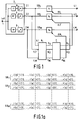
- Fig. 1 shows the coding system.
- a wideband digital signal is applied to the input terminal 1.
- the audio signal may be a stereo audio signal. In that case only one of the two signal components (left or right signal component) of the stereo audio signal will be discussed. The same will happen then with the other signal component.
- 16-bit samples of the left signal component of the audio signal are applied to the input 1 with a sampling frequency of 44 kHz.
- the audio signal is applied to a subband coder 2 which comprises signal splitting means.
- the subband coder 2 splits up the audio signal into M subbands by means of M filters, that is to say, a low-pass filter LP, M-2 band-pass filters BP and a high-pass filter HP.
- M is equal to 32.
- the sampling frequency of the M subband signals is reduced in the blocks referenced 9. The sampling frequency is reduced therein by a factor of M.
- the signals thus obtained are presented at the outputs 3.1, 3.2, ..., 3.M.
- the signal in the lowest subband SB1 is presented at output 3.1.
- the signal in the lowest but one subband SB2 is presented at output 3.2.
- the signal in the highest subband SB M is presented at the output 3.M.
- the signals at the outputs 3.1 to 3.M have the form of successive samples expressed in 16 or over, for example, 24-bit numbers.
- the samples of the left subband signal component appear at the outputs 3.1 to 3.M of Fig. 1. These samples are referenced l[k].
- the subband coding system for the right signal component of the audio signal similarly produces samples r[k] of the right signal component in the subbands SB1 to SB M . This is shown in Fig. 1a.
- the subbands SB1 to SB M have all the same width. This is not necessary, however.
- Prior-art publication (5), Krasner discusses for example, a subdivision into a number of subbands whose bandwidths approximately correspond to the bandwidths of the critical bands of the human auditory system in the respective frequency ranges.
- the subband signals are combined in successive signal blocks of q successive samples, cf . Fig. 1a, and applied to the associated quantizers Q1 to Q M .
- a quantizer Q m the samples are quantized to quantized samples having a number of bits n m smaller than 16.
- Fig. 1 shows how the left subband signals are applied to an associated quantizer Q m in signal blocks of q successive samples which are the samples l[l] to l[q].
- the right subband signals are applied to an associated quantizer (not shown) in signal blocks of q successive samples which are the samples r[l] to r[q].
- q is equal to 12.
- the signal blocks (groups) of q successive samples of the subband signal components are quantized to a smaller number of bits.
- the q samples in a signal block are first normalized. This normalization is effected by dividing the amplitudes of the q samples by the amplitude of the sample having the largest absolute value in the signal block.
- the amplitude of the sample having the largest amplitude in the signal block of the subband SB m provides the scale factor SF m , cf . document (2a), (2b).
- the amplitudes of the normalized samples, which are now situated in an amplitude range from -1 to +1 are quantized.
- the quantized samples in the subbands SB l to SB M are thereafter presented at the respective outputs 4.1 to 4.M.
- the outputs 3.1 to 3.M are further coupled to the respective inputs 5.1 to 5.M of the bit need determining means 6.
- the bit need determining means 6 determine the bit needs b ml and b mr for q-sample signal blocks corresponding with time of the left and right subband signal components in the subbands SB l to SB M .
- the bit needs b ml and b mr are numbers related to the number of bits with which the q samples in a q-sample signal block of the left or right subband signal components respectively, of a signal of the subband m ought to be quantized.
- bit needs b ll to b Ml , and b lr to b Mr derived by the bit need determining means 6 are applied to bit allocation means 7.
- the bit allocation means 7 determine, on the basis of the bit needs, the real number of bits n ll to n Ml and n lr to n Mr with which the q samples of the corresponding signal blocks of the left and right subband signal components in the subband signals SB l to SB M are quantized.
- Control signals corresponding to the numbers n ll to n Ml are applied to the respective quantizers Q l to Q M over the lines 8.1 to 8.M, so that the quantizers are capable of quantizing the samples with the correct numbers of bits.
- control signals corresponding to the numbers n lr to n Mr are applied to associated quantizers (not shown) for the right subband signal components, so that also these quantizers are capable of quantizing the samples of the right subband signal components with the correct numbers of bits.
- the publication (2b) of the reference list describes how in a stereo intensity mode the left and right subband signal components in a subband are combined in one or more subbands, cf . more particularly the description of Fig. 15c in the publication (2b).
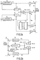
- Fig. 2a shows the structure of this part of the coding system in the publication (2b), which performs a stereo intensity coding of the left and right subband signal components in a subband SB m .
- the input terminal 10 is constantly supplied with q-sample signal blocks of the first subband signal component i.e. the left subband signal component in the subband SB m .
- the input terminal 11 is constantly supplied with q-sample signal blocks of the second subband signal component i.e. the right subband signal component in the subband SB m .
- the left subband signal component referenced l is applied both to a unit 12 and a divider 14. In the unit 12 a scale factor SF l is determined for each signal block in the left subband signal component.
- This scale factor is equal to, for example, the amplitude of the largest sample in the signal block.
- the divider 14 all the samples of the signal block are divided by the scale factor SF l .
- the output of the divider 14 then presents normalized samples referenced l[k] where k varies from 1 to q.
- the samples l[k] are applied to a first input of a signal combining unit 16 formed by an adder.
- the right subband signal component referenced r is applied both to the unit 13 and to a divider 15.
- a scale factor SF r is determined for each signal block in the right subband signal component, which factor is in this case also equal to the amplitude of the largest sample of the signal block.
- the divider 15 In the divider 15 all the samples in the signal block are divided by the scale factor SF r . The output of the divider 15 then presents normalized samples r[k] which are applied to a second input of the signal combining unit 16. Also in this case k varies from 1 to q. In an additional divider 17 the summed samples l[k]+r[k] are divided by 2. The samples thus obtained are applied to the quantizer 18.
- the bit need determining means 6 and the bit allocation means 7 determine, in the manner described, for example, in the documents (9a) and (9b), the number of bits n mc by which the samples in the signal block of the composite subband signal in the subband SB m are to be represented.
- the quantized signal block of the composite subband signal quantized in the quantizer 18 is then applied to the input 20 of a transmission medium 23.
- the scale factors SF l and SF r belonging to the corresponding signal blocks in the left and right subband signal components are applied, after quantization in the quantizers 36 and 37 respectively, to the respective inputs 19 and 22 of the transmission medium 23.
- the allocation information n mc denoting the number of bits by which the samples in the signal block of the quantized composite subband signal are represented, are applied, subsequent to quantization in the quantizer 35, to the input 21 of the transmission medium 23.
- the method described above is constantly repeated for successive corresponding signal blocks in the left and right signal components of the subband SB m .
- the transmission medium 23 may have the form of a wireless transmission such as, for example, a radio transmit channel. However, other transmission mediums are also possible.
- optical transmission for example, through optical fibres or optical record carriers such as compact disc-like media, or a transmission by means of magnetic record carriers utilizing, for example, RDAT or SDAT-like recording or reproducing techniques as described, for example, in document (8) in the reference list.
- the q-sample signal block of the composite subband signal in the subband SB m is derived from the data stream of the quantized samples applied to a dequantizer 29 through the input 26 in response to the allocation information n mc also applied to the dequantizer 29 through the input 25.
- This method is extensively discussed in document (2b) of the reference list.
- the samples thus obtained are then applied to multipliers 30 and 31.
- the scale factor information is also derived from the data stream sent to the receiver via the transmission medium 23. This scale factor information comprises the scale factors SF l and SF r which are also applied to the multipliers 30 and 31 through the inputs 27 and 28 respectively.
- the samples in the signal block of the composite subband signal are multiplied by SF l and SF r in the multipliers 30 and 31 respectively.
- the outputs 32 and 33 then present the left and right subband signal components respectively, in the subband SB m .
- the samples l[k] and r[k] belonging together in corresponding signal blocks of the left and right subband signal components may be plotted as points in a plane formed by a fictive co-ordinate system, the amplitude l[k] being plotted along one axis of the co-ordinate system and the amplitude r[k] being plotted along the other axis.
- Fig. 3 shows this co-ordinate system.
- P1, P2, P3 and P4 denote four points corresponding to the first four samples that belong together (l[l],r[l]), (l[2],r[2]), (l[3],r[3]) and (l[4],r[4]) in corresponding signal blocks in the left and right signal components of the subband SB m .
- Samples belonging together are added up in the adder 16 to become composite samples l[k]+r[k], divided by two in the divider 17 and transmitted via the transmission medium 23 after being quantized in the quantizer 18.
- the composite samples are applied to both multipliers 30 and 31.
- the samples belonging together and applied to the multipliers 30 and 31 may also be plotted as points in the plane shown in Fig. 3, the amplitude of the sample applied to the multiplier 30 being plotted along the l-axis and the amplitude of the sample applied to the multiplier 31 being plotted along the r-axis. This provides the points P1', P2', P3' and P4'.
- the coding and subsequent decoding does not cause any difficulties. This is due to the fact that the amplitude of the composite sample is relatively large compared to a specific noise level.
- the sample pairs corresponding to the points P3 and P4 are obtained from samples l[k] and r[k] which also have a relatively large amplitude compared to the noise level.
- Fig. 3 shows, however, that the projections of these points on the dashed line lead to composite samples having a relatively small amplitude. This amplitude may be so small as to be of the order of the noise level.
- the multiplication of these composite samples in the multipliers 30 and 31 produces reconstructed samples l r [k] and r r [k] which have a poor signal-to-noise ratio and are thus unreliable.
- the cloud of the q points P k (l[k],r[k]) does not coincide with the line I-I, but is more or less perpendicular to this line.
- projections on the line I-I lead to composite samples having amplitudes which are in most cases very small relative to the amplitudes of the original samples.
- the conclusion of this may be that once the line I-I does not optimally traverse the cloud of points, the coding as described above does not lead to good transmission.
- a coding system is proposed according to the invention, in which a projection is made on a line traversing the cloud of points in the best way possible depending on the position of this cloud of points.
- Fig. 4a shows the situation in which a q-point cloud of points is traversed by the line I-I. The angle ⁇ 1 is thus equal to 45°.
- Fig. 4b shows the situation in which the q-point cloud of points is traversed by the line I'-I' which is at an angle ⁇ 2 relative to the l-axis, which angle is smaller than 45°.
- Fig. 4c shows a q-point cloud of points which is optimally traversed by the line I''-I''.
- the angle ⁇ 3 is about 135°.
- Fig. 5 shows a cloud of points from one of the Figs. 4a, 4b and 4c after transformation to the I-E co-ordinate system according to the above rotation transformation.
- the l-axis after rotation coincides with the I-axis and the r-axis coincides after rotation with the E-axis.
- the transformation of the cloud of points in Fig. 4a to the cloud of points in Fig. 5 means a rotation through an angle ⁇ equal to - ⁇ 1.
- the transformation of the cloud of points in Fig. 4b to Fig. 5 means a rotation through an angle ⁇ equal to - ⁇ 2.
- the transformation of the cloud of points of Fig. 4c to Fig. 5 means a rotation through an angle ⁇ equal to - ⁇ 3.
- the coding at the transmitter end which was based according to the known method on the projection of the points (l,[k],r[k]) on the line I-I in the l-r co-ordinate system, cf . Fig. 3, is now transformed to a coding in the form of a projection of the points (I[k],E[k]) on the I-axis in the I-E co-ordinate system of Fig. 5.
- the projections of the points (I[k],E[k]) on the I-axis are transmitted via the transmission medium. This means that q samples I[k] in a signal block of the composite subband signal are transmitted.
- the I-axis in Fig. 5 is actually the intensity axis and the E-axis is thus the error axis.
- the angle ⁇ is then selected such that is minimized.
- the corresponding signal blocks of the first and second subband signal components in a subband are encoded in the intensity mode if the values E[k] obtained after rotation are small enough. This actually means that the error in the intensity coding is to be smaller than a specific value. If the error is too large, the signal blocks are not encoded in the intensity mode but the normal coding system as described in the documents (9a) and (9b) is performed separately on the corresponding signal blocks in the subband signal components of a subband. Another possibility is that in that case both E[k] and I[k] are transmitted. Possible decision criterions for switching the stereo intensity mode on or off are to be discussed at some later instant.
- Fig. 6 shows an exemplary embodiment of the system according to the invention which is able to code the subband signal components in a subband in the intensity mode.
- the inputs 10 and 11 are supplied with the samples l[k] and r[k] respectively, of corresponding signal blocks in the subband signal components.
- the samples l[k] and r[k] need not first be divided by the scale factors SF l and SF r respectively as was the case in the system shown in Fig. 2.
- the samples l[k] are applied to a unit 40 and a multiplier 41.
- the samples r[k] are also applied to the unit 40 and to a multiplier 42.
- the unit 40 determines, on the basis of the criterion to be discussed hereinafter, whether the relevant subband can be coded in the intensity mode. If this is the case the unit 40 derives the angle ⁇ from the samples l[l] to l[q] and r[l] to r[q] of the corresponding signal blocks in the fashion described above. Actually, the unit 40 determines the angle ⁇ of the lines I-I, I'-I' and I''-I'' in Fig. 4. Within a certain quantization accuracy range ⁇ is then equal to - ⁇ . For the lines located in the first and third quadrants of the l-r co-ordinate system shown in Fig. 4, such as the lines I-I and I'-I' in Figs.
- the unit 40 presents the value for ⁇ at an output for the value ⁇ to be applied to the multipliers 41 and 42.
- the multiplier 41 the samples l[l] to l[q] are multiplied by cos ⁇ and in the multiplier 42 the samples r[l] to r[q] are multiplied by - sin ⁇ .
- Outputs of the multipliers 41 and 42 are coupled to corresponding inputs of the adder 16.
- I[k] l[k]cos ⁇ -r[k]sin ⁇
- the multipliers 45 and 46 multiply the scale factor SF lr by cos ⁇ and -sin ⁇ respectively.
- the respective scale factors SF l and SF r then appear at the outputs of the multipliers 45 and 46.
- the scale factors are quantized in the quantizers 36 and 37 and applied to the transmission medium through the inputs 19 and 22.
- the receiver side in Fig. 6b may in fact be identical with the receiver side in Fig. 2b, and thus means no further explanation.
- the scale factor SF lr and the angle ⁇ could be transmitted.
- the scale factors SF l and SF r could then be reconstructed from SF lr and ⁇ . This is diagrammatically shown in Fig. 6c.
- the scale factors SF l and SF r are first derived and then multiplied by the composite samples so as to produce the samples in the left and right signal components.
- the composite samples could first be multiplied by SF lr at the receiver end and the samples thus obtained could be multiplied by cos ⁇ so as to obtain the left signal component, and by -sin ⁇ so as to obtain the right signal component. This is diagrammatically shown in Fig. 6d.
- multipliers 45 and 46 produce the scale factors SF l and SF r belonging to the original subband signal components.
- the coding at the transmitter end is based on the matrix multiplication as represented above.
- Fig. 7 represents the behaviour of cos ⁇ and sin ⁇ in the region between - ⁇ /2 and ⁇ /2 and thus the behaviour of the sign of SF l and SF r .
- SF lr is always a positive number. This means that SF r has a negative value if ⁇ is situated between 0 and ⁇ /2. This is thus valid in the cases where the cloud of points (l[k],r[k]) is located in the second and fourth quadrants of the co-ordinate system shown in Fig. 4c.
- the result of this is that at least one sign bit for one of the scale factors is to be transmitted.
- the format with which the whole data stream is to be transmitted through the transmission medium is then to be taken into consideration.
- the intensity mode can only be used for frequencies over about 1500 Hz. For each subband in this frequency range and for each q-sample signal block in the left and right subband signal components it has to be decided whether this subband is either or not coded in the intensity mode. Two criterions will be discussed.
- the first criterion starts from an E[k] which is small relative to the signal energy in the subband concerned. In that case a subband is coded in the intensity mode if where D is an arbitrary threshold. If this criterion is compared with the situations shown in Fig. 4, it appears that in all the cases that satisfy this criterion, the cloud of points l[k],r[k] has a cigar-like shape. Consequently, after the rotation transformation the magnitudes E[k] are small. In these cases an intensity coding will be permissible. However, if the cloud of points was more circular, an intensity coding would not be permitted.
- masking may be stated from. There may be derived that the power of the error occurring by omitting the samples E[k] for the left channel is produced by the formula and for the right channel by the formula Omission is permitted if the error in the two channels is masked.
- the exemplary embodiment of the system according to the invention means that at least one sign bit for a scale factor is to be transmitted via the transmission medium.
- the exemplary embodiment which will be discussed hereinafter renders transmitting the sign bit redundant, whereas yet a better transmission may be realised than with prior-art system shown in Fig. 2.
- This second exemplary embodiment is based on the system shown in Fig. 6, where an adaptation is realised in the unit 40.
- the section of the system shown in Fig. 6a is located between the inputs 10 and 11 and the adder 16.
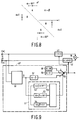
- the unit 40 is shown in more detail in Fig. 9 and referenced by the reference numeral 40'.
- the unit 40' comprises a block 50 which determines the angle ⁇ of the projection lines I-I, I'-I' and I''-I'' in the Figs. 4a, 4b and 4c in above manner.
- a detector 52 detects whether ⁇ is situated between 0 and 90°. If this is the case, the detector 52 applies a detection signal to the control signal generator 55.
- a detector 53 in the comparing unit 51 detects whether ⁇ is situated between 90 and 135°. If this is the case, the detector 53 applies a detection signal to the generator 55.
- the detector 54 detects whether ⁇ is situated between -45° and 0°. If this is the case, the detector 54 applies a detection signal to the generator 55.
- the generator 55 produces first, second or third control signals respectively, to be applied to a control signal input of a controllable switch 56.
- the switch 56 In response to the first control signal the switch 56 connects the terminals a and d. This means that a value ⁇ equal to - ⁇ appears at the output of the unit 40', cf. block 57 in the unit 40' where ⁇ is assumed to be equal to - ⁇ .
- the switch 56 In response to the second control signal the switch 56 connects the terminals c and d. Due to the presence of block 58 in the unit 40', which in this case is coupled to the output of the unit 40', a value for a equal to -90° appears at this output.
- Fig. 8 clarifies that this coding produces a better transmission than the coding described for the system shown in Fig. 2.
- the projection on the r-axis shown in Fig. 8 produces a better approximate of the original samples than the projection on the line I-I in Fig. 3.
- the switch 56 In response to the third control signal the switch 56 connects the terminals b and d. Due to the presence of the block 59 in the unit 40', which is in this case coupled to the output of the unit 40', a value for a equal to 0° appears at this output.
- the third control signal characterizes a situation in which the cloud of points l[k],r[k] is essentially located in the parts of the plane shown in Fig. 8 referenced B. Because ⁇ is in this case assumed to be equal to 0°, this means that a coding of the points is performed in the form of a projection on the l-axis and that only these projections are transmitted via the transmission medium as samples of the composite subband signal. This is immediately clear from Fig.
- Fig. 10 shows this measure implemented in the transmitter according to the invention.
- Fig. 10 shows only the relevant transmitter section of the system shown in Fig. 6a.
- the scale factors were determined in the units 45 and 46. These units are omitted in the exemplary embodiment of Fig. 10 and replaced by the units 65 and 66.
- a first input of the unit 65 is coupled to the input terminal 10 through which the unit 65 is supplied with the samples l[l] to l[q] in a signal block.
- a second input is coupled to the output of the divider 43, so that the unit 65 is supplied with the composite samples i[l] to i[q] through this second input.
- Unit 65 is capable of computing the scale factor SF l from these input signals with the aid of above formula.
- a first input of the unit 66 is coupled to the input terminal 11 and a second input is coupled to the output of the divider 43.
- the unit 66 computes the scale factor SF r on the basis of the signals supplied through these inputs.
- This correction is again implemented in Fig. 11 in a system according to the invention such as the one described, for example, in Fig. 6 or 10. However, it should be observed in this respect that this correction may also be used in systems according to the state of the art which are capable of applying an intensity mode coding to the left and right signal components of a subband.
- the samples i[k] at the transmitter end are first to be divided by (l+ ⁇ ).
- the relevant section of the system which is capable of making corrections for the other value of the quantized scale factor SF l is represented in Fig. 11.
- at least one sign bit for one of the scale factors is to be determined as described hereinbefore with reference to Fig. 6a. This sign bit may then be added to the associated scale factors after which transmission may be effected.
- the output of the quantizer 36 is coupled to the input of a dequantizer 70 in which the quantized scale factor SF l is again dequantized.
- the dequantizer thus produces a value SF' l of the quantized scale factor SF l .
- the outputs of the dequantizer 70 and the unit 36 are coupled to inputs of a divider 71 in which a division of SF' l /SF l is performed for obtaining the value l+ ⁇ .
- This value is applied to a divider 72 inserted between the divider 43 and the quantizer 18.
- the samples i[k] are divided by the value l+ ⁇ .
- a compensation is made for the quantizing error resulting from the quantization of the scale factor SF l .
- the power in the left channel remains constant.
- Fig. 12 shows an exemplary embodiment in which the quantization error in SF l as well as the quantization error in SF r are taken into consideration. Therefore, the system shown in Fig. 12 comprises a dequantizer 75, a divider 76 and a divider 77.
- a compromise is reached so that corrections are made at least partly for the quantization errors in the scale factors in both channels.
- This measure is also applicable to aforementioned state-of-the-art systems.
- a still further possibility would be to detect for each signal block of the left signal component and the corresponding signal block of the right subband signal component which of the two signal blocks is louder, and correct the scale factor belonging to the subband signal component which is the louder in accordance with the method shown in Fig. 11.
- correction factor in the unit 77 is a function of the values (l+ ⁇ ) and (l+ ⁇ ), which function may then further be determined by the value of the scale factors and/or the energies of the two signal components.
- Fig. 13 shows the use of the subband coder as described hereinbefore, in a transmitter, more particularly, a transmitter in the form of a recording device for recording the quantized subband signals in one or more tracks on a magnetic record carrier.
- the section referenced 130 is the afore-discussed subband coder presenting the quantized subband signals at the outputs 4.1 to 4.M.
- the output 4.M actually covers two separate outputs at which the quantized subband signal components are presented.
- the q quantized samples of two corresponding signal blocks in the first and second signal components of the subband m can be presented consecutively at the output 4.m.
- the quantized composite subband signal is presented at an output 4.m. Furthermore, two quantized scale factors SF' l and SF' r for each subband are presented at an output of the section 130. Allocation information for each subband is likewise presented at an output of the section 130. For a subband m, for which the first and second subband signal components are processed separately, the allocation information is thus generated for each subband signal component. Thus, for a subband m processed in the intensity mode, only the allocation information is generated for the quantized composite subband signal.
- the section referenced 131 converts all these signals and includes these signals in a second digital signal to be presented at the output 132.
- This second digital signal is constituted by successive frames whose format is extensively discussed in prior-art documents (2a) and (2b). Also the structure of the block 131 is explained in these documents.
- the section referenced 133 renders the second digital signal suitable for recording on a record carrier, for example, a magnetic record carrier 134.
- the unit 133 thereto comprises an 8-to-10 converter. In such a converter 8-bit data words in the serial information stream are converted to 10-bit codewords. Interleaving may also be effected. All this is aimed at making an error correction of the received information possible at the receive end (when the record carrier is reproduced).
- the output signal of block 133 is applied to write means 135 by which the signal is recorded in one or more longitudinal tracks on the record carrier 134.
- the write means 135 thereto comprise one or more write heads 136.
Landscapes
- Engineering & Computer Science (AREA)
- Physics & Mathematics (AREA)
- Signal Processing (AREA)
- General Physics & Mathematics (AREA)
- Multimedia (AREA)
- Computer Networks & Wireless Communication (AREA)
- Theoretical Computer Science (AREA)
- Discrete Mathematics (AREA)
- Mathematical Physics (AREA)
- Computational Linguistics (AREA)
- Health & Medical Sciences (AREA)
- Audiology, Speech & Language Pathology (AREA)
- Human Computer Interaction (AREA)
- Acoustics & Sound (AREA)
- Computer Security & Cryptography (AREA)
- Compression, Expansion, Code Conversion, And Decoders (AREA)
- Transmission Systems Not Characterized By The Medium Used For Transmission (AREA)
- Signal Processing For Digital Recording And Reproducing (AREA)
Applications Claiming Priority (2)
| Application Number | Priority Date | Filing Date | Title |
|---|---|---|---|
| NL9100173A NL9100173A (nl) | 1991-02-01 | 1991-02-01 | Subbandkodeerinrichting, en een zender voorzien van de kodeerinrichting. |
| NL9100173 | 1991-02-01 |
Publications (2)
| Publication Number | Publication Date |
|---|---|
| EP0497413A1 true EP0497413A1 (fr) | 1992-08-05 |
| EP0497413B1 EP0497413B1 (fr) | 1996-04-24 |
Family
ID=19858808
Family Applications (1)
| Application Number | Title | Priority Date | Filing Date |
|---|---|---|---|
| EP92200195A Expired - Lifetime EP0497413B1 (fr) | 1991-02-01 | 1992-01-24 | Dispositif de codage par sous-bandes et émetteur muni de ce dispositif |
Country Status (6)
| Country | Link |
|---|---|
| US (1) | US5621855A (fr) |
| EP (1) | EP0497413B1 (fr) |
| JP (1) | JPH04360331A (fr) |
| KR (1) | KR920017399A (fr) |
| DE (1) | DE69210064T2 (fr) |
| NL (1) | NL9100173A (fr) |
Cited By (18)
| Publication number | Priority date | Publication date | Assignee | Title |
|---|---|---|---|---|
| WO1995012254A1 (fr) * | 1993-10-27 | 1995-05-04 | Philips Electronics N.V. | Emission et reception de premiere et deuxieme composantes principales de signal |
| WO1998003037A1 (fr) * | 1996-07-12 | 1998-01-22 | Fraunhofer-Gesellschaft zur Förderung der angewandten Forschung e.V. | Codage et decodage de signaux audio au moyen d'un procede stereo en intensite et de prediction |
| US5812971A (en) * | 1996-03-22 | 1998-09-22 | Lucent Technologies Inc. | Enhanced joint stereo coding method using temporal envelope shaping |
| US5850456A (en) * | 1996-02-08 | 1998-12-15 | U.S. Philips Corporation | 7-channel transmission, compatible with 5-channel transmission and 2-channel transmission |
| US5850418A (en) * | 1994-05-02 | 1998-12-15 | U.S. Philips Corporation | Encoding system and encoding method for encoding a digital signal having at least a first and a second digital component |
| US5864800A (en) * | 1995-01-05 | 1999-01-26 | Sony Corporation | Methods and apparatus for processing digital signals by allocation of subband signals and recording medium therefor |
| US5909664A (en) * | 1991-01-08 | 1999-06-01 | Ray Milton Dolby | Method and apparatus for encoding and decoding audio information representing three-dimensional sound fields |
| US5960037A (en) * | 1996-04-10 | 1999-09-28 | U.S. Phillips Corporation | Encoding of a plurality of information signals |
| WO1999052326A1 (fr) * | 1998-04-07 | 1999-10-14 | Ray Milton Dolby | Systeme de codage spatial a faible debit binaire et procede correspondant |
| US6038369A (en) * | 1996-09-10 | 2000-03-14 | Sony Corporation | Signal recording method and apparatus, recording medium and signal processing method |
| WO2005059899A1 (fr) * | 2003-12-19 | 2005-06-30 | Telefonaktiebolaget Lm Ericsson (Publ) | Codage de longueur de trames variables a fidelite optimisee |
| WO2008064577A1 (fr) * | 2006-12-01 | 2008-06-05 | Huawei Technologies Co., Ltd. | Procédé et appareil permettant d'ajuster la qualité de la quantification dans un codeur et décodeur |
| RU2374703C2 (ru) * | 2003-10-30 | 2009-11-27 | Конинклейке Филипс Электроникс Н.В. | Кодирование или декодирование аудиосигнала |
| US7725324B2 (en) | 2003-12-19 | 2010-05-25 | Telefonaktiebolaget Lm Ericsson (Publ) | Constrained filter encoding of polyphonic signals |
| US7809579B2 (en) | 2003-12-19 | 2010-10-05 | Telefonaktiebolaget Lm Ericsson (Publ) | Fidelity-optimized variable frame length encoding |
| US7822617B2 (en) | 2005-02-23 | 2010-10-26 | Telefonaktiebolaget Lm Ericsson (Publ) | Optimized fidelity and reduced signaling in multi-channel audio encoding |
| EP2456236A1 (fr) | 2003-12-19 | 2012-05-23 | Telefonaktiebolaget L M Ericsson AB (Publ) | Codage sur filtre en mode contraint pour signaux polyphoniques |
| US8218775B2 (en) | 2007-09-19 | 2012-07-10 | Telefonaktiebolaget L M Ericsson (Publ) | Joint enhancement of multi-channel audio |
Families Citing this family (26)
| Publication number | Priority date | Publication date | Assignee | Title |
|---|---|---|---|---|
| DE69331166T2 (de) * | 1992-02-03 | 2002-08-22 | Koninklijke Philips Electronics N.V., Eindhoven | Übertragung von digitalen Breitbandsignalen |
| TW221836B (fr) * | 1992-06-09 | 1994-03-21 | Philips Electronics Nv | |
| JP3277699B2 (ja) * | 1994-06-13 | 2002-04-22 | ソニー株式会社 | 信号符号化方法及び装置並びに信号復号化方法及び装置 |
| CA2184541A1 (fr) | 1996-08-30 | 1998-03-01 | Tet Hin Yeap | Methode et appareil de modulation de signaux par ondelettes pour fins de transmission et/ou de stockage |
| JP3279228B2 (ja) * | 1997-08-09 | 2002-04-30 | 日本電気株式会社 | 符号化音声復号装置 |
| WO1999033194A1 (fr) * | 1997-12-19 | 1999-07-01 | Sgs-Thomson Microelectronics Asia Pacific (Pte) Ltd. | Procede et appareil d'estimation de phase dans un codeur a transformee pour l'obtention de signaux audio de haute qualite |
| US6591241B1 (en) * | 1997-12-27 | 2003-07-08 | Stmicroelectronics Asia Pacific Pte Limited | Selecting a coupling scheme for each subband for estimation of coupling parameters in a transform coder for high quality audio |
| US6931372B1 (en) | 1999-01-27 | 2005-08-16 | Agere Systems Inc. | Joint multiple program coding for digital audio broadcasting and other applications |
| EP1500085B1 (fr) * | 2002-04-10 | 2013-02-20 | Koninklijke Philips Electronics N.V. | Codage de signaux stereo |
| JP4805541B2 (ja) * | 2002-04-10 | 2011-11-02 | コーニンクレッカ フィリップス エレクトロニクス エヌ ヴィ | ステレオ信号の符号化 |
| EP1500084B1 (fr) * | 2002-04-22 | 2008-01-23 | Koninklijke Philips Electronics N.V. | Representation parametrique d'un signal audio spatial |
| US20030220800A1 (en) * | 2002-05-21 | 2003-11-27 | Budnikov Dmitry N. | Coding multichannel audio signals |
| US7453945B2 (en) * | 2003-09-05 | 2008-11-18 | Lucent Technologies Inc. | Methods and devices for controlling RF, multi-carrier amplifier signal power |
| ATE390683T1 (de) * | 2004-03-01 | 2008-04-15 | Dolby Lab Licensing Corp | Mehrkanalige audiocodierung |
| EP1735778A1 (fr) * | 2004-04-05 | 2006-12-27 | Koninklijke Philips Electronics N.V. | Procedes et dispositifs destines au codage et au decodage de signaux stereo |
| TWI393121B (zh) * | 2004-08-25 | 2013-04-11 | 杜比實驗室特許公司 | 處理一組n個聲音信號之方法與裝置及與其相關聯之電腦程式 |
| TWI393120B (zh) | 2004-08-25 | 2013-04-11 | Dolby Lab Licensing Corp | 用於音訊信號編碼及解碼之方法和系統、音訊信號編碼器、音訊信號解碼器、攜帶有位元流之電腦可讀取媒體、及儲存於電腦可讀取媒體上的電腦程式 |
| KR101183859B1 (ko) * | 2004-11-04 | 2012-09-19 | 코닌클리케 필립스 일렉트로닉스 엔.브이. | 다중채널 오디오 신호들의 인코딩 및 디코딩 |
| KR100707177B1 (ko) * | 2005-01-19 | 2007-04-13 | 삼성전자주식회사 | 디지털 신호 부호화/복호화 방법 및 장치 |
| WO2007052612A1 (fr) * | 2005-10-31 | 2007-05-10 | Matsushita Electric Industrial Co., Ltd. | Dispositif de codage stéréo et méthode de prédiction de signal stéréo |
| US8385556B1 (en) * | 2007-08-17 | 2013-02-26 | Dts, Inc. | Parametric stereo conversion system and method |
| CN101673548B (zh) * | 2008-09-08 | 2012-08-08 | 华为技术有限公司 | 参数立体声编码方法、装置和参数立体声解码方法、装置 |
| EP2345027B1 (fr) | 2008-10-10 | 2018-04-18 | Telefonaktiebolaget LM Ericsson (publ) | Codage et décodage audio multicanal conservant l'énergie |
| CN103152062B (zh) * | 2013-01-28 | 2014-11-12 | 中国电子科技集团公司第二十二研究所 | 一种实时信号的生成方法及装置 |
| TWI579831B (zh) * | 2013-09-12 | 2017-04-21 | 杜比國際公司 | 用於參數量化的方法、用於量化的參數之解量化方法及其電腦可讀取的媒體、音頻編碼器、音頻解碼器及音頻系統 |
| US11030777B2 (en) * | 2018-09-14 | 2021-06-08 | Sony Group Corporation | Adaptive subband coding for lifting transform |
Citations (3)
| Publication number | Priority date | Publication date | Assignee | Title |
|---|---|---|---|---|
| EP0176243A2 (fr) * | 1984-08-24 | 1986-04-02 | BRITISH TELECOMMUNICATIONS public limited company | Codage de la parole dans le domaine des fréquences |
| GB2224185A (en) * | 1987-08-26 | 1990-04-25 | Vnii Radiovesh Priema Akustiki | Device for coding and decoding sound broadcast signals |
| EP0402973A1 (fr) * | 1989-06-02 | 1990-12-19 | Koninklijke Philips Electronics N.V. | Système de transmission numérique, émetteur et récepteur destinés à être utilisés dans le système de transmission ainsi que support d'enregistrement obtenu au moyen du transmetteur sous forme d'appareil enregistreur |
Family Cites Families (9)
| Publication number | Priority date | Publication date | Assignee | Title |
|---|---|---|---|---|
| DE3167257D1 (en) * | 1981-02-27 | 1985-01-03 | Ibm | Transmission methods and apparatus for implementing the method |
| DE3171990D1 (en) * | 1981-04-30 | 1985-10-03 | Ibm | Speech coding methods and apparatus for carrying out the method |
| EP0085820B1 (fr) * | 1982-02-09 | 1985-11-21 | International Business Machines Corporation | Procédé de transmission numérique multi-vitesses et dispositif de mise en oeuvre dudit procédé |
| NL8700985A (nl) * | 1987-04-27 | 1988-11-16 | Philips Nv | Systeem voor sub-band codering van een digitaal audiosignaal. |
| EP0400222A1 (fr) * | 1989-06-02 | 1990-12-05 | ETAT FRANCAIS représenté par le Ministère des Postes, des Télécommunications et de l'Espace | Système de transmission numérique utilisant le codage par sous-bandes d'un signal numérique |
| NL9000635A (nl) * | 1990-03-20 | 1991-10-16 | Philips Nv | Digitaal opteken- en weergavesysteem. |
| US5367608A (en) * | 1990-05-14 | 1994-11-22 | U.S. Philips Corporation | Transmitter, encoding system and method employing use of a bit allocation unit for subband coding a digital signal |
| US5365553A (en) * | 1990-11-30 | 1994-11-15 | U.S. Philips Corporation | Transmitter, encoding system and method employing use of a bit need determiner for subband coding a digital signal |
| US5323390A (en) * | 1992-10-20 | 1994-06-21 | At&T Bell Laboratories | Multirate, sonet-ready, switching arrangement |
-
1991
- 1991-02-01 NL NL9100173A patent/NL9100173A/nl not_active Application Discontinuation
-
1992
- 1992-01-24 DE DE69210064T patent/DE69210064T2/de not_active Expired - Fee Related
- 1992-01-24 EP EP92200195A patent/EP0497413B1/fr not_active Expired - Lifetime
- 1992-01-29 KR KR1019920001277A patent/KR920017399A/ko not_active Ceased
- 1992-01-31 JP JP4016954A patent/JPH04360331A/ja active Pending
-
1994
- 1994-10-19 US US08/326,145 patent/US5621855A/en not_active Expired - Fee Related
Patent Citations (3)
| Publication number | Priority date | Publication date | Assignee | Title |
|---|---|---|---|---|
| EP0176243A2 (fr) * | 1984-08-24 | 1986-04-02 | BRITISH TELECOMMUNICATIONS public limited company | Codage de la parole dans le domaine des fréquences |
| GB2224185A (en) * | 1987-08-26 | 1990-04-25 | Vnii Radiovesh Priema Akustiki | Device for coding and decoding sound broadcast signals |
| EP0402973A1 (fr) * | 1989-06-02 | 1990-12-19 | Koninklijke Philips Electronics N.V. | Système de transmission numérique, émetteur et récepteur destinés à être utilisés dans le système de transmission ainsi que support d'enregistrement obtenu au moyen du transmetteur sous forme d'appareil enregistreur |
Cited By (30)
| Publication number | Priority date | Publication date | Assignee | Title |
|---|---|---|---|---|
| US6021386A (en) * | 1991-01-08 | 2000-02-01 | Dolby Laboratories Licensing Corporation | Coding method and apparatus for multiple channels of audio information representing three-dimensional sound fields |
| US5909664A (en) * | 1991-01-08 | 1999-06-01 | Ray Milton Dolby | Method and apparatus for encoding and decoding audio information representing three-dimensional sound fields |
| WO1995012254A1 (fr) * | 1993-10-27 | 1995-05-04 | Philips Electronics N.V. | Emission et reception de premiere et deuxieme composantes principales de signal |
| US5850418A (en) * | 1994-05-02 | 1998-12-15 | U.S. Philips Corporation | Encoding system and encoding method for encoding a digital signal having at least a first and a second digital component |
| US5864800A (en) * | 1995-01-05 | 1999-01-26 | Sony Corporation | Methods and apparatus for processing digital signals by allocation of subband signals and recording medium therefor |
| US5850456A (en) * | 1996-02-08 | 1998-12-15 | U.S. Philips Corporation | 7-channel transmission, compatible with 5-channel transmission and 2-channel transmission |
| US5812971A (en) * | 1996-03-22 | 1998-09-22 | Lucent Technologies Inc. | Enhanced joint stereo coding method using temporal envelope shaping |
| US5960037A (en) * | 1996-04-10 | 1999-09-28 | U.S. Phillips Corporation | Encoding of a plurality of information signals |
| AU707665B2 (en) * | 1996-07-12 | 1999-07-15 | At&T Laboratories/Research | Coding and decoding of audio signals using intensity stereo and prediction |
| US6341165B1 (en) | 1996-07-12 | 2002-01-22 | Fraunhofer-Gesellschaft zur Förderdung der Angewandten Forschung E.V. | Coding and decoding of audio signals by using intensity stereo and prediction processes |
| WO1998003037A1 (fr) * | 1996-07-12 | 1998-01-22 | Fraunhofer-Gesellschaft zur Förderung der angewandten Forschung e.V. | Codage et decodage de signaux audio au moyen d'un procede stereo en intensite et de prediction |
| US6038369A (en) * | 1996-09-10 | 2000-03-14 | Sony Corporation | Signal recording method and apparatus, recording medium and signal processing method |
| WO1999052326A1 (fr) * | 1998-04-07 | 1999-10-14 | Ray Milton Dolby | Systeme de codage spatial a faible debit binaire et procede correspondant |
| US6016473A (en) * | 1998-04-07 | 2000-01-18 | Dolby; Ray M. | Low bit-rate spatial coding method and system |
| EP1677576A3 (fr) * | 1998-04-07 | 2007-06-27 | Dolby Laboratories Licensing Corporation | Système de codage spatial a faible debit binaire et procédé correspondant |
| KR100828952B1 (ko) * | 1998-04-07 | 2008-05-13 | 돌비 레버러토리즈 라이쎈싱 코오포레이션 | 저 비트속도 공간 코딩방법 및 시스템 |
| RU2374703C2 (ru) * | 2003-10-30 | 2009-11-27 | Конинклейке Филипс Электроникс Н.В. | Кодирование или декодирование аудиосигнала |
| US8260607B2 (en) | 2003-10-30 | 2012-09-04 | Koninklijke Philips Electronics, N.V. | Audio signal encoding or decoding |
| US8073685B2 (en) | 2003-10-30 | 2011-12-06 | Koninklijke Philips Electronics, N.V. | Audio signal encoding or decoding |
| WO2005059899A1 (fr) * | 2003-12-19 | 2005-06-30 | Telefonaktiebolaget Lm Ericsson (Publ) | Codage de longueur de trames variables a fidelite optimisee |
| CN100559465C (zh) * | 2003-12-19 | 2009-11-11 | 艾利森电话股份有限公司 | 保真度优化的可变帧长编码 |
| US7725324B2 (en) | 2003-12-19 | 2010-05-25 | Telefonaktiebolaget Lm Ericsson (Publ) | Constrained filter encoding of polyphonic signals |
| US7809579B2 (en) | 2003-12-19 | 2010-10-05 | Telefonaktiebolaget Lm Ericsson (Publ) | Fidelity-optimized variable frame length encoding |
| EP2456236A1 (fr) | 2003-12-19 | 2012-05-23 | Telefonaktiebolaget L M Ericsson AB (Publ) | Codage sur filtre en mode contraint pour signaux polyphoniques |
| RU2305870C2 (ru) * | 2003-12-19 | 2007-09-10 | Телефонактиеболагет Лм Эрикссон (Пабл) | Оптимизированное по точности кодирование с переменной длиной кадра |
| US7822617B2 (en) | 2005-02-23 | 2010-10-26 | Telefonaktiebolaget Lm Ericsson (Publ) | Optimized fidelity and reduced signaling in multi-channel audio encoding |
| US7945055B2 (en) | 2005-02-23 | 2011-05-17 | Telefonaktiebolaget Lm Ericcson (Publ) | Filter smoothing in multi-channel audio encoding and/or decoding |
| US9626973B2 (en) | 2005-02-23 | 2017-04-18 | Telefonaktiebolaget L M Ericsson (Publ) | Adaptive bit allocation for multi-channel audio encoding |
| WO2008064577A1 (fr) * | 2006-12-01 | 2008-06-05 | Huawei Technologies Co., Ltd. | Procédé et appareil permettant d'ajuster la qualité de la quantification dans un codeur et décodeur |
| US8218775B2 (en) | 2007-09-19 | 2012-07-10 | Telefonaktiebolaget L M Ericsson (Publ) | Joint enhancement of multi-channel audio |
Also Published As
| Publication number | Publication date |
|---|---|
| JPH04360331A (ja) | 1992-12-14 |
| US5621855A (en) | 1997-04-15 |
| KR920017399A (ko) | 1992-09-26 |
| NL9100173A (nl) | 1992-09-01 |
| EP0497413B1 (fr) | 1996-04-24 |
| DE69210064T2 (de) | 1996-11-21 |
| DE69210064D1 (de) | 1996-05-30 |
Similar Documents
| Publication | Publication Date | Title |
|---|---|---|
| EP0497413B1 (fr) | Dispositif de codage par sous-bandes et émetteur muni de ce dispositif | |
| US5530750A (en) | Apparatus, method, and system for compressing a digital input signal in more than one compression mode | |
| USRE39080E1 (en) | Rate loop processor for perceptual encoder/decoder | |
| JP3498375B2 (ja) | ディジタル・オーディオ信号記録装置 | |
| US5864800A (en) | Methods and apparatus for processing digital signals by allocation of subband signals and recording medium therefor | |
| JP3318825B2 (ja) | デジタル信号符号化処理方法、デジタル信号符号化処理装置、デジタル信号記録方法、デジタル信号記録装置、記録媒体、デジタル信号伝送方法及びデジタル信号伝送装置 | |
| EP0457390B1 (fr) | Dispositif de codage comportant un codeur de sous-bande et émetteur muni du dispositif | |
| US6353584B1 (en) | Reproducing and recording apparatus, decoding apparatus, recording apparatus, reproducing and recording method, decoding method and recording method | |
| EP0691751B1 (fr) | Procede et appareil de compression d'informations, et appareil d'enregistrement/emission d'informations comprimees | |
| EP0775389B1 (fr) | Systeme et procede de codage visant a coder un signal numerique possedant au moins un premier et un second composant | |
| KR100321015B1 (ko) | 제1및제2주신호성분을송수신하는송수신기 | |
| US5440596A (en) | Transmitter, receiver and record carrier in a digital transmission system | |
| JP3879250B2 (ja) | エンコード方法、デコード方法、エンコード装置、デコード装置、ディジタル信号記録方法、ディジタル信号記録装置、記録媒体、ディジタル信号送信方法及びディジタル信号送信装置 | |
| USRE40280E1 (en) | Rate loop processor for perceptual encoder/decoder | |
| EP1046239B1 (fr) | Procede et appareil d'estimation de phase dans un codeur a transformee pour l'obtention de signaux audio de haute qualite | |
| JP3318824B2 (ja) | デジタル信号符号化処理方法、デジタル信号符号化処理装置、デジタル信号記録方法、デジタル信号記録装置、記録媒体、デジタル信号伝送方法及びデジタル信号伝送装置 | |
| JPH09102742A (ja) | 符号化方法および装置、復号化方法および装置、並びに記録媒体 | |
| EP0853842B1 (fr) | Codage d'une pluralite de signaux d'informations | |
| JP3879249B2 (ja) | エンコード方法、デコード方法、エンコード装置、デコード装置、ディジタル信号記録方法、ディジタル信号記録装置、記録媒体、ディジタル信号送信方法及びディジタル信号送信装置 | |
| JP3827720B2 (ja) | 差分コーディング原理を用いる送信システム | |
| JPH08181619A (ja) | ディジタル信号圧縮方法及び装置、並びに記録媒体 | |
| EP0573103B1 (fr) | Système de transmission numérique | |
| EP0554934B1 (fr) | Transmission de signaux numerique à bande large | |
| JPH07193510A (ja) | ディジタル信号処理装置、ディジタル信号処理方法、及び記録媒体 | |
| JPH11272294A (ja) | エンコード方法、デコード方法、エンコード装置、デコード装置、ディジタル信号記録方法、ディジタル信号記録装置、記録媒体、ディジタル信号送信方法及びディジタル信号送信装置 |
Legal Events
| Date | Code | Title | Description |
|---|---|---|---|
| PUAI | Public reference made under article 153(3) epc to a published international application that has entered the european phase |
Free format text: ORIGINAL CODE: 0009012 |
|
| AK | Designated contracting states |
Kind code of ref document: A1 Designated state(s): DE FR GB IT |
|
| 17P | Request for examination filed |
Effective date: 19930203 |
|
| 17Q | First examination report despatched |
Effective date: 19950315 |
|
| GRAH | Despatch of communication of intention to grant a patent |
Free format text: ORIGINAL CODE: EPIDOS IGRA |
|
| GRAA | (expected) grant |
Free format text: ORIGINAL CODE: 0009210 |
|
| AK | Designated contracting states |
Kind code of ref document: B1 Designated state(s): DE FR GB IT |
|
| REF | Corresponds to: |
Ref document number: 69210064 Country of ref document: DE Date of ref document: 19960530 |
|
| ET | Fr: translation filed | ||
| ITF | It: translation for a ep patent filed | ||
| PLBE | No opposition filed within time limit |
Free format text: ORIGINAL CODE: 0009261 |
|
| STAA | Information on the status of an ep patent application or granted ep patent |
Free format text: STATUS: NO OPPOSITION FILED WITHIN TIME LIMIT |
|
| 26N | No opposition filed | ||
| PGFP | Annual fee paid to national office [announced via postgrant information from national office to epo] |
Ref country code: GB Payment date: 19971229 Year of fee payment: 7 |
|
| PGFP | Annual fee paid to national office [announced via postgrant information from national office to epo] |
Ref country code: FR Payment date: 19980120 Year of fee payment: 7 |
|
| PGFP | Annual fee paid to national office [announced via postgrant information from national office to epo] |
Ref country code: DE Payment date: 19980323 Year of fee payment: 7 |
|
| REG | Reference to a national code |
Ref country code: FR Ref legal event code: CD |
|
| PG25 | Lapsed in a contracting state [announced via postgrant information from national office to epo] |
Ref country code: GB Free format text: LAPSE BECAUSE OF NON-PAYMENT OF DUE FEES Effective date: 19990124 |
|
| GBPC | Gb: european patent ceased through non-payment of renewal fee |
Effective date: 19990124 |
|
| PG25 | Lapsed in a contracting state [announced via postgrant information from national office to epo] |
Ref country code: FR Free format text: LAPSE BECAUSE OF NON-PAYMENT OF DUE FEES Effective date: 19990930 |
|
| PG25 | Lapsed in a contracting state [announced via postgrant information from national office to epo] |
Ref country code: DE Free format text: LAPSE BECAUSE OF NON-PAYMENT OF DUE FEES Effective date: 19991103 |
|
| REG | Reference to a national code |
Ref country code: FR Ref legal event code: ST |
|
| PG25 | Lapsed in a contracting state [announced via postgrant information from national office to epo] |
Ref country code: IT Free format text: LAPSE BECAUSE OF NON-PAYMENT OF DUE FEES Effective date: 20050124 |