EP0498106A2 - Procédé d'attribution d'éléments d'images aux cellules d'une trame en demi-teintes - Google Patents
Procédé d'attribution d'éléments d'images aux cellules d'une trame en demi-teintes Download PDFInfo
- Publication number
- EP0498106A2 EP0498106A2 EP91309007A EP91309007A EP0498106A2 EP 0498106 A2 EP0498106 A2 EP 0498106A2 EP 91309007 A EP91309007 A EP 91309007A EP 91309007 A EP91309007 A EP 91309007A EP 0498106 A2 EP0498106 A2 EP 0498106A2
- Authority
- EP
- European Patent Office
- Prior art keywords
- cell
- ideal
- pixels
- cells
- halftone
- Prior art date
- Legal status (The legal status is an assumption and is not a legal conclusion. Google has not performed a legal analysis and makes no representation as to the accuracy of the status listed.)
- Granted
Links
- 238000000034 method Methods 0.000 title claims abstract description 143
- 239000013598 vector Substances 0.000 claims description 53
- 239000011159 matrix material Substances 0.000 claims description 24
- 230000003190 augmentative effect Effects 0.000 claims description 5
- 230000003292 diminished effect Effects 0.000 claims description 4
- 238000010276 construction Methods 0.000 claims 1
- 238000004519 manufacturing process Methods 0.000 abstract description 2
- 230000008569 process Effects 0.000 description 11
- 238000012545 processing Methods 0.000 description 11
- 230000006870 function Effects 0.000 description 10
- 238000013519 translation Methods 0.000 description 9
- 230000014616 translation Effects 0.000 description 9
- 238000009826 distribution Methods 0.000 description 5
- 238000002372 labelling Methods 0.000 description 4
- 238000006467 substitution reaction Methods 0.000 description 4
- 230000008901 benefit Effects 0.000 description 3
- 238000004422 calculation algorithm Methods 0.000 description 3
- 230000003247 decreasing effect Effects 0.000 description 3
- 230000006872 improvement Effects 0.000 description 3
- 238000003491 array Methods 0.000 description 2
- 238000004364 calculation method Methods 0.000 description 2
- 238000004590 computer program Methods 0.000 description 2
- 230000008030 elimination Effects 0.000 description 2
- 238000003379 elimination reaction Methods 0.000 description 2
- 238000007620 mathematical function Methods 0.000 description 2
- 238000007639 printing Methods 0.000 description 2
- 230000008859 change Effects 0.000 description 1
- 238000012993 chemical processing Methods 0.000 description 1
- 238000012937 correction Methods 0.000 description 1
- 230000001186 cumulative effect Effects 0.000 description 1
- 230000006735 deficit Effects 0.000 description 1
- 238000013461 design Methods 0.000 description 1
- 230000000694 effects Effects 0.000 description 1
- 230000014509 gene expression Effects 0.000 description 1
- 230000004048 modification Effects 0.000 description 1
- 238000012986 modification Methods 0.000 description 1
- 238000007645 offset printing Methods 0.000 description 1
- 230000000644 propagated effect Effects 0.000 description 1
- 238000009877 rendering Methods 0.000 description 1
- 238000005070 sampling Methods 0.000 description 1
- 230000009466 transformation Effects 0.000 description 1
- 238000000844 transformation Methods 0.000 description 1
- 238000009827 uniform distribution Methods 0.000 description 1
Images



Classifications
-
- H—ELECTRICITY
- H04—ELECTRIC COMMUNICATION TECHNIQUE
- H04N—PICTORIAL COMMUNICATION, e.g. TELEVISION
- H04N1/00—Scanning, transmission or reproduction of documents or the like, e.g. facsimile transmission; Details thereof
- H04N1/40—Picture signal circuits
- H04N1/405—Halftoning, i.e. converting the picture signal of a continuous-tone original into a corresponding signal showing only two levels
- H04N1/4055—Halftoning, i.e. converting the picture signal of a continuous-tone original into a corresponding signal showing only two levels producing a clustered dots or a size modulated halftone pattern
- H04N1/4058—Halftoning, i.e. converting the picture signal of a continuous-tone original into a corresponding signal showing only two levels producing a clustered dots or a size modulated halftone pattern with details for producing a halftone screen at an oblique angle
Definitions
- This invention relates to the creation of a digital halftone grid that includes multiple halftone cells which can be used for the creation of halftone images.
- the invention also provides management of pixel allocation to digital halftone cells for the elimination of undesired image spots or bands caused by uncontrolled clustering of pixels.
- Continuous tone images do not print well on most printing devices, so the image is usually printed as pattern of dots based on a grid.
- the grid consists of an array of halftone cells, each of which represents one section of continuous tone in the original image.
- a halftone cell consists of a plurality of device pixels. A portion of the display pixels of each halftone cell are turned black to form dots relatively larger or smaller to represent darker or lighter portions of the original continuous tone image. A dark halftone cell will have most of the pixels turned black, while a light halftone cell will have most of the pixels turned white.
- a complete grid of the original image is composed of many such halftone cells, each of which has an independent density of displayed pixels and therefore a different apparent darkness when viewed from a distance.
- a common prior art method of selecting which dots in each halftone cell to turn black works as follows. For a given halftone cell, the original image is sampled at each display pixel location in the halftone cell to obtain a gray value. This gray value is represented digitally as a number in a fixed range, typically 0 to 255. The gray value is then compared to a threshold value in the same range and the display pixel is turned white if the gray value is greater than the threshold value, or otherwise black.
- the threshold values are supplied by means of a threshold array which contains a separate threshold value for each pixel in the halftone cell, and is computed ahead of time prior to processing the image. This process is carried out for each halftone cell of the image.
- the multiple halftone cells in such a threshold array generally have to be of differing shapes and sizes when those halftone cells are represented by display pixels. This means that the dots produced by the different half-tone cells may also be of different shapes and sizes even when they represent the same gray value. Depending on the degree of difference in the size and shape of halftone dots, these differences may or may not be visible to the human eye. When these differences are visible, one sees a mottled variation in gray intensity in the form of repeating spots or bands where the original image contained only a constant gray. Such patterns do not faithfully reproduce the original image and are thus undesirable.
- An ideal halftone cell, or ideal cell for short will be a halftone cell, such as is discussed above, which is an element of the halftone grid consisting of an area bounded by a rotated square or a parallelogram.
- a digital halftone cell, or digital cell for short will be a set of pixels used to approximate an ideal halftone cell.
- each digital halftone cell is associated with the specific ideal halftone cell which it approximates.
- a threshold array that consists of multiple halftone cells will be referred to as "supertile".
- a digital halftone cell consists of all the pixels in the supertile whose geometric centers fall within the associated ideal cell.
- This method creates digital halftone cells of satisfactory consistency for certain halftone screens, but for other screens an unsatisfactory variation in digital cell size resulted.
- These variations occur because, although each ideal cell has the same shape, its placement with respect to the pixel grid varies by fractional amounts of pixels so that in some cases, more pixel centers would fall inside an ideal cell and in other cases fewer pixel centers would fall inside an ideal cell.
- the resulting variations in the size of the digital halftone cells cause corresponding variations in the size of halftone dots when certain values of gray are reproduced. This will be known as the "unequal cell size problem".
- the present invention describes a method for the creation of digital halftone cells from among the pixels in a supertile so as to make all such digital halftone cells as nearly the same size as possible, while at the same time still faithfully approximating the shape of the associated ideal cells.
- the method of the invention for dividing pixels in a supertile into digital halftone cells, which approximate ideal halftone cells starts by superimposing a halftone grid made up of halftone cells on the supertile.
- a first group of pixels of the supertile is assigned to the digital cell, each of which is located entirely within a single ideal halftone cell.
- a second group of pixels of the supertile is assigned to the digital cell, a portion of each of which lies in the ideal halftone cell and a portion of which lies in at least one other ideal halftone cell.
- the method of this invention may be practiced using any of several devices which preferably includes a scanner, a computer and some type of raster display device.
- An original image is mechanically or electronically scanned and then calculated, programmed or otherwise prepared for reproduction.
- a supertile generally containing more than one halftone cell, is constructed to approximate the screen angle and screen dot frequency desired by the user.
- a set of digital halftone cells is then constructed from the pixels of the supertile according to one of the four embodiments of this invention to insure that the areas of all digital halftone cells in the supertile are as equal as possible, and all the digital halftone cells resemble their associated ideal halftone cells as closely as possible.
- the image to be reproduced is divided into image portions corresponding to a tiling of the image by the supertile. Each such image portion is then thresholded against the supertile to determine the binary (on/off) setting of each corresponding display pixel.
- the binary information can then be buffered in computer memory or fed directly to the recording device.
- the invention provides an improved method for producing halftone images when using a threshold array, or supertile, that contains more than one halftone cell, so that spurious patterns of gray spots or gray bands are avoided in areas where the true image is a relatively constant gray level.
- the first method computes quickly and requires only a small amount of computing memory, but in some cases it produces a less than optimal result.
- the second method requires more memory and computation, but it often produces a better result than the first.
- Floor(x) is the greatest integer smaller than or equal to the floating point value x.
- Mod(p, q) is the remainder left upon dividing the integer q by the integer p. It can also be defined as [p - Floor(p/q) * q].
- GCD(p, q) is the positive greatest common divisor of the integers p and q.
- Extended GCD(p, q, &r, &s) executes the extended greatest common divisor (see page 325 of The Art of Computer Programming, Volume 2 / Seminumerical Algorithms , by Donald Knuth, published by Addison Wesley, incorporated herein by reference). This computes integers r and s from integers p and q such that p*r + q*s is the positive greatest common divisor of p and q.
- the arguments r and s to the function are prefixed with the "&" sign to indicate that values are returned through these arguments.
- Sin(x) is the sine function applied to x.
- Cos(x) is the cosine function applied to x.
- Device Space An area of a two dimensional plane in which the recording device can make black marks on a white background or vice versa.
- Device Location Any point in device space. Device locations can be specified by a pair of numbers in one of the two coordinate systems described below, referring to Figure 2 unless otherwise noted.
- the recording device can only mark certain discrete areas in device space. Each such area is called a device pixel or a generic pixel 110.
- Device Coordinates A coordinate system used to describe the locations of device pixels.
- the device pixels of any device can be assumed to reside in a rectangular array.
- the pixel coordinates (x,y) refer to the pixel in the y-th row and the x-th column.
- a device pixel at location (x,y) will be assumed to be the pixel that covers the area of a square whose corners are given by (x,y), (x+1,y), (x+1,y+1), (x,y+1), where x and y are integers.
- Most marking devices are not this precise, but the above convention will be useful in explaining the processes described below.
- Halftone Grid 220 A grid of squares, larger than the device pixels and generally rotated with respect to the device coordinate system. This grid controls the placement of halftone dots. In an analog system, halftone dots are circles centered exactly at the center of squares in the halftone grid. The embodiments of the method of the invention described below will also work if the halftone grid is a made up of parallelograms instead of squares.
- a second coordinate system this one based on the halftone grid so that integer coordinates in this system correspond to the corners of ideal halftone cells.
- the origin of the cell coordinate system is assumed to coincide with the origin of the device coordinate system.
- Coordinates in the device coordinate system, (x,y) can be converted to coordinates in the cell coordinate system, (u,y), by the following C-language computation:
- the variables d11, d12, d21 and d22 are computed from the parameters of the desired halftone screen.
- the parameters of the halftone screen may be specified in terms of following variables: (1) "angle”, the angle of the screen with respect the device x-coordinate axis; and (2) "length", the length of one side of an ideal halftone cell measured in the device coordinate system.
- d11, d12, d21 and d22 would be computed as follows:
- Ideal halftone cell (ideal cell) 120 A single square in the halftone grid 220. This will also be referred to as an ideal cell 120. If the numbers r and s are integers, the cell coordinates, (r,s) will refer to the ideal cell whose four corners are (r,s), (r+1, s), (r+1, s+1), (r, s+1) in cell coordinates. To provide an unambiguous way to determine in which ideal cell a certain location in device space falls, the following convention will be used: a location in device space, designated by cell coordinates (u,v), lies in the ideal cell, designated by (r,s), exactly when r equals Floor(u) and s equals Floor(s).
- Digital halftone cell (digital cell) 130 ( Figure 4): A group of generic pixels 110 that approximates in shape and size an associated ideal cell 120. Since the sides of ideal cell 120 do not in general coincide with the boundaries of pixels, a digital cell 130 can only approximate ideal cell 120 to within one generic pixel 110 in accuracy. A particular digital cell will be referred to by the cell coordinates of the associated ideal cell.
- Halftone dot 150 ( Figure 4): For a given gray level, the set of generic pixels 110 turned black (or white for a white dot) in the digital halftone cell 130. When using a digital rendering system, each halftone dot is made up of device pixels and the ideal dot can only be approximated due to the discrete nature of the pixels. See Figure 2.
- Supertile 140 ( Figure 2): For a given halftone grid 220, U.S Patent Application Serial No. 434,924 , incorporated herein by reference, discussed above, shows how to construct the supertile 140.
- This supertile is a set of device pixels 110 with the following properties:
- Supertile Translation Vectors As was mentioned above, the supertile can be translated to cover device space. Any such translation of the supertile can be accomplished via successive translations by the two supertile translation vectors.
- the two vectors have the values (sx,sy) and (-sy,sx) in device coordinates.
- Threshold Array ( Figure 2): A term commonly used in halftoning practice to denote a set of generic (device) pixels 110 that tile the plane (condition number 1 under the definition of supertile 140) where each generic pixel 110 is given a "threshold value".
- Such threshold arrays are used to generate halftoned images as follows. First, the plane is tiled with the threshold array. Thus, each generic pixel 110 is covered by a copy of the threshold array and therefore can be associated with the threshold value of the generic pixel 110 covering it in this copy of the threshold array. Next the desired gray value for the generic pixel 110 is computed from the image being halftoned and compared to the threshold value. If the gray level is greater than the threshold value, the generic pixel 110 is left white; otherwise it is marked black.
- the supertile 140 mentioned above is calculated in order to define the set of pixels of the threshold array. Since the supertile encompasses multiple ideal halftone cells, so will the threshold array.
- the first method of the invention for correcting the unequal cell size problem will now be described with reference to Figures 1 and 2, and, when indicated, Figure 4.
- the first method is called the fast equal area correction method, and it operates according to the following explanation.
- the supertile dimensions are computed from the parameters of the desired halftone screen according to the method of co-pending U.S. Patent Application Serial No. 434,924 , incorporated herein by reference. As noted above, this supertile will have dimensions sx and sy.
- the halftone grid is positioned with respect to the device coordinate system so that a corner of the halftone grid will fall exactly on the origin of the device coordinate system.
- the halftone grid divides the supertile into a plurality of ideal cells. Some of these ideal cells may be split by the supertile boundary. In that case, part of the ideal cell may lie on one side of the supertile, while the remaining part or parts lie on other sides of the supertile boundary.
- FIG 2 several instances of such cells are illustrated. For example, the pieces marked 7 and 7' may be assembled to form one ideal cell. All such pieces of ideal cells may be assembled to form whole ideal cells.
- variable K the number of ideal cells contained in the supertile, after any split ideal cells are reassembled into whole ideal cells.
- the object of the method of this embodiment is to select generic pixels 110 to assign to ideal cells 120 included in supertile 140. Once this is done, all of the generic pixels assigned to a given ideal cell, called c, will comprise a digital cell called c' which can then replace ideal cell c in a digital halftoning system, as shown in Figure 4.
- a generic pixel 110 may lie entirely inside an ideal halftone cell, in which case it will be referred to as an interior pixel 114, or it may lie on a boundary between two or more ideal cells 120, in which case it will be called a boundary pixel 111.
- An interior pixel will be assigned to the ideal cell containing it. This will be the first step of the first method of the invention described below. But first a method is needed for distinguishing these two kinds of pixels and computing in which ideal cell(s) they fall.
- certain ideal cells in the selected supertile may be split into pieces, which are referred to as partial ideal cells.
- these partial ideal cells which will generally not be contiguous, are treated as if they belong to the same ideal cell.
- the partial ideal cells labeled 7 and 7' are considered to belong to the same ideal cell.
- the informal reason for this is that if a copy of the supertile in Figure 2 were translated by the supertile translation vector (sx, sy), then the copy of partial ideal cell 7' in this translated supertile would complete the original partial ideal cell 7 into a whole ideal cell.
- all partial ideal cells in the supertile are considered to belong to the same ideal cell if they belong to "equivalent" ideal cells in the sense defined in the Terminology Section.
- cell identifier This integer will be referred to as the "cell identifier", or "cell id” for short and will have the following desirable properties: (a) each distinct cell in the supertile will have a different cell id; and (b) pieces of ideal cells that belong to equivalent cells will have the same cell id.
- the method works by computing a set, ⁇ S ⁇ consisting of K ideal cells, none of which is split into pieces, such that each ideal cell in set ⁇ S ⁇ is equivalent to exactly one ideal cell in the supertile.
- the set ⁇ S ⁇ can be chosen so that the ideal cells in set ⁇ S ⁇ can easily be described by their cell coordinates: an ideal cell with cell coordinates (u,v) is in ⁇ S ⁇ if u is greater than or equal to 0 and less than maxU, while v is greater than or equal to 0 and less than maxV. MaxU and maxV will be determined below.
- Cell id numbers can now be computed for any ideal cell as follows.
- an ideal cell is in ⁇ S ⁇ and has cell coordinates (u,v), it has a cell id of u + v*maxU.
- An ideal cell, c1 outside of set ⁇ S ⁇ is translated by the two supertile translation vectors until it falls on an ideal cell, c2, within ⁇ S ⁇ . The cell id of c2 is then given to c1.
- the numbers, maxU and maxV depend only on the dimensions of the supertile, sx and sy, and the variables d11, d12, d21, d22, that convert from device coordinates to cell coordinates.
- maxU and maxV can be computed ahead of time and stored as global variables.
- the C-language source code for this is as follows: The line of the code "int dx, dy, ex, ey" declares four integer variables whose names are listed. Note that this code also computes a variable "offset" which will be used in the next step of the method. Now the cell coordinates (u,v) can be converted to the cell id, ci, by the following source code: This completes the calculation of the cell id.
- the numbers in the centers of the ideal cells in Figure 2 are cell id's computed by this method.
- the method for calculating the ideal cell in which a pair of device coordinates falls given in the above code segment 3 is augmented by taking the values u and v computed by that code and computing the cell id ci as in code segment 5 above.
- the method for detecting and assigning interior pixels into ideal cells will now be provided.
- the cell id numbers of the ideal cells that device locations (x,y), (x+1,y), (x+1,y+1), (x,y+1) fall inside are computed using code segments 3 and 5. These cell id numbers will be called c1, c2, c3, c4. If c1, c2, c3, c4 are all equal, then the generic pixel having device coordinates (x,y) will be assigned to the ideal cell with cell id number c1.
- a boundary pixel 111 or 112 may overlap 2, 3 or 4 ideal cells.
- the boundary pixels are not assigned to any ideal cell.
- a boundary pixel 111 or 112 will be assigned to only one of the ideal cells which it overlaps.
- the following data structures are used.
- the first data structure consists of an array of records, one for each boundary pixel 111 or 112 in Figure 4, each record containing the following information about the boundary pixel:
- the above code segment 6 also declares the array variable, bpArray and sets aside memory for 10,000 records of the above type in this variable. This amount is about right for many applications but can be made larger, smaller, or dynamically allocated as needed. Not all 10,000 structures are typically used, the global variable, numBP, tells how many of these records have information stored in them.
- cellID may be in any order, but whatever that order is, the list of overlap areas stored in the field "area” are stored in the same order. In other words, if cellID[i] equals c, then area[i] is the overlap of the boundary pixel with ideal cell.
- the first step of the method is to fill in the records in the array variable, bpArray, with valid information for each boundary pixel in the supertile and set the variable, numBP, to the number of valid records in the array. This is done by identifying each of the boundary pixels 111 overlapping each side of each ideal cell in the supertile and filling in a record of bpArray for each of these boundary pixels 111.
- the set ⁇ S ⁇ consists of those ideal cells with cell coordinates (u,v) such that u is an integer in the range from 0 to maxU-1 inclusive and v is an integer in the range from 0 to maxV-1 inclusive.
- u is an integer in the range from 0 to maxU-1 inclusive
- v is an integer in the range from 0 to maxV-1 inclusive.
- the method of identifying the boundary pixels overlapping one of the above type-1 sides is the same for all such sides.
- the cell coordinates of end point 301 will be (u,v) and the cell coordinates of end point 302 will be (u+1,v).
- the coordinates of both end points are converted to device coordinates (x1,y1) and (x2,y2) respectively according to code segment 1 and 2 above.
- the cell id numbers are calculated for the ideal cells whose cell coordinates are (u,v-1), (u,v), (u-1,v-1), (u-1,v), (u+1, v-1), (u+1,v).
- the cell id numbers being stored in variables c1, c2, c3, c4, c5, c6 respectively. For example see Figure 3 where the respective ideal cells have been labeled 311, 312, 313, 314, 315, 316.
- the prior art method known as Pitteway tracking is then used to identify sequentially each boundary pixel on the line segment from (x1,y1) to (x2,y2).
- the method gives device coordinates (x,y) for each boundary pixel thus identified.
- code segments 3 and 5 are used to compute the cell id for each ideal cell within which each of the four corners, (x,y), (x+1,y), (x+1,y+1), (x,y+1) of the generic pixel lies.
- These cell id numbers are stored as the variables r,s,t,u.
- Line 310 is the line passing through cell coordinates (u,v) and (u,v+1).
- well known techniques of analytic geometry are applied to compute the area of the portion of the boundary pixel on the same side of line 310 as is ideal cell c3, in variable a3, and the area of the remaining portion in variable a4. The following three cases are to be considered:
- This method does not handle the case where a pixel overlaps both, one of c3 or c4, and one of c5 or c6. In fact this cannot happen in the practical case where the length of a side of an ideal cell is longer than three pixels. This condition is declared in the beginning of the software code that is used to execute this method.
- boundary pixels identified are on the line segment from cell coordinates (u,v) to (u,v+1) and that the variables c1, c2, c3, c4, c5, c6 are the cell id numbers of the ideal cells with cell coordinates (u-1,v), (u,v), (u-1,v-1), (u,v-1), (u-1, v+1), (u,v+1) respectively.
- variable, numBP which is the number of records stored in the array so far, can also be used as the index into the array to the next available record.
- boundary pixel B can be uniquely defined by the index i of the corresponding structure in the array. In the following descriptions we will say simply that boundary pixel B has an index i.
- Another of the data structures used by the method of the first embodiment of the invention is an array of K fixed or floating point numbers, this array being denoted by the variable areaError, K being the number of ideal cells in the supertile.
- the areaError variable for each ideal cell 120 will be indexed by the cell id number ci of the ideal cell and will be denoted areaError[ci].
- the area error variables tell how the area of each digital cell differs from the area of the associated ideal cell, even when the assignments of the generic pixels 110 to digital cells 130 are only partially completed. Thus, the areaError variables have to be updated each time a boundary pixel is assigned to an ideal cell.
- boundary pixel indexed by i
- i overlaps two ideal cells with cell id numbers c and d.
- these entities are called "boundary pixel i", “ideal cell c” and “ideal cell d”. Similar abbreviations of terminology will be used in the remaining description.
- boundary pixel i in an ideal cell c.
- the areaError for ideal cell c is increased by the area of the portion of the boundary pixel i outside of ideal cell c.
- areaError[c] is increased by the additional area gained from including boundary pixel i in the associated digital cell.
- the areaError for an ideal cell d is decreased by an amount equal to the area of the portion of boundary pixel i inside ideal cell d.
- areaError[d] is decreased by the area lost by assigning boundary pixel i to another ideal cell.
- statements starting with the C-language construct "if” next contain a condition in parentheses which, if true, cause the statement which follows to be executed. If such a series of statements is then followed by the C-language construct "else”, then the statement following the "else” is executed (provided the parenthetical condition after the previous "if” is false). The statements subordinate to the "if” are further indented to indicate this subordination.
- the next step in the first embodiment of the first method is to take all corner pixels 112, which are boundary pixels 111 that overlap more than two ideal cells 120, (i.e., the boundary pixels 111 which occur where four ideal cells 120 meet at a common corner), and simply assign them to the ideal cell 120 with which they have the most overlap area. Since corner pixels 112 are in the minority, there are plenty of other boundary pixels 111 available to even out the areas of the ideal cells 120 after this first step.
- the next step of the method of the invention consists of a loop that considers in turn each ideal cell 120 in the supertile 140.
- the ideal cells are enumerated in increasing order of the their cell id numbers. With ci as the current cell id, what happens in the body of the loop will now be described in reference to Figures 2 and 4.
- bpList a list is made of all the boundary pixels which overlap ideal cell c and which have not yet been assigned to any ideal cell. This list is denoted by the variable name bpList.
- the elements in bpList are first obtained by going through all the elements in bpArray and copying those which overlap ideal cell c but which have not been assigned to any ideal cell.
- the elements in bpList are then regrouped according to which ideal cell (other than ideal cell c) they overlap. As mentioned above all pixels overlapping more than two ideal cells have already been assigned, so any remaining boundary pixels must overlap exactly two ideal cells.
- the boundary pixels within each of these four side groups in bpList are further sorted by their x or y coordinates. For example, if the line between ideal cell r and ideal cell c is mostly horizontal, then the sorting of side group r is according to the x coordinate; if that line is mostly vertical, the sorting is according to the y coordinate. "Usually horizontal” is defined as making an angle of greater than or equal to -45° and less than 45° with the x-axis in the device coordinate system. Any other line is "mostly vertical". This sorting operation is carried out within each of the four side groups without altering the overall composition of each side group.
- boundary pixels in this list are assigned to ideal cells according to the method to be set forth below.
- Each boundary pixel 111 is considered in the order it is encountered in the list bpList.
- the decision as to whether to assign a given boundary pixel i to the ideal cell c or to the other ideal cell it overlaps is based on keeping the area error, calculated by code segment 7, for ideal cell c between the bounds -1/2 and less then +1/2.
- 1/2 means half the area of the boundary pixel. If assigning boundary pixel i to ideal cell c would make its area error less than +1/2, then the assignment is made to ideal cell c. Otherwise boundary pixel is assigned to the only other ideal cell which it overlaps.
- the area error for the last ideal cell to be processed must balance the sum of the area error variables for all previously processed cells. If this technique only controlled the individual area errors to be between -1/2 and 1/2, the sum of the first K-1 area error variables could be as large as (K-1)/2, and this error would all be propagated to the last ideal cell.
- Code segment 8 below is a partial listing of the source code that implements the method described above. The parts of the code dealing with sorting the elements in the array bpList are indicated by procedure calls instead of being written out in their entirety. These sorting techniques involved are well known in the art. Note that the procedure AssignBoundaryPixel is defined above in code segment 7.
- variable areaError[c] may not be zero any longer when ideal cell c is processed by the main loop above. This is because each time a boundary pixel 111 is assigned to one ideal cell 120, the area errors of two ideal cells 120 are up-dated. These are the area error of the ideal cell 120 currently being worked on and the area error of the other ideal cell 120 that the boundary pixel 111 overlaps. Thus, if ideal cell c is adjacent to an ideal cell that has already been processed, areaError[c] could be non zero when processing starts on ideal cell c.
- a second problem which is also tolerable in many applications is that a boundary pixel 111 which is 90% in ideal cell 120 (called c) and 10% in ideal cell 120 (called u) may end up in ideal cell u.
- the probability that it will end up in cell u is only 10%, based upon the reasonable assumption that the current value of areaError[c] at any point in the method can be modeled as a random variable with uniform distribution in the range from -1/2 to 1/2.
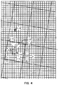
- Boundary pixels 111 such as this one may be attached to the rest of the generic pixels 110 in a digital cell 130 by only one vertex, which creates digital cells 130 of odd shape, as illustrated in Figure 5.
- non-linearities in the physical or chemical processing of the media used by the recording device are brought out by the odd-shaped digital cell 130 resulting from the application of the first embodiment, which can cause unpredictable inking in the output.
- the second embodiment of the first method works best when the tilt angle of the halftone grid 220 is close to 45° relative to the axis of the device coordinate system.
- the third embodiment works best when the tilt angle of the halftone grid 220 is closer to 0° or 90° relative to the axis of the device coordinate system.
- the second embodiment will now be described.
- the second embodiment consists of a modification to the main loop of the first embodiment (which was set forth in code segment 8).
- ideal cells are processed, one at a time, in increasing order of their cell id numbers.
- the explanation below will focus on the processing of a single ideal cell c.
- a list is made of the boundary pixels, denoted by the variable bpList, which overlap ideal cell c and which haven't been assigned to any other ideal cell yet.
- the boundary pixels in bpList are then grouped into side groups. Also as in the first embodiment, the boundary pixels within each of these side groups are further sorted by their x or y coordinates. The point of departure from the first embodiment is the manner in which boundary pixels in this list are assigned to one ideal cell or the other, after the list bpList has been sorted.
- each side group of the boundary pixels in bpList which are all adjacent to the same other ideal cell, for example r are processed as a group. Since the boundary pixels in bpList are already sorted into side groups, we can identify indices, rStart and rEnd, such that all the boundary pixels in bpList which overlap ideal cell r are indexed by an integer j, where j is between rStart and rEnd, inclusive.
- the values of rStart and rEnd can be computed easily by inspecting successive elements in the array bpList and recording the indices of the first and last elements in the array which overlap the ideal cell r.
- the next step in the second embodiment is to compute the variable pixArea, which is the area of the intersection of all boundary pixels in bpList overlapping both ideal cell c and ideal cell r, with ideal cell c.
- the next step is to compute the variable assignPix which is the number of boundary pixels 111 that are adjacent to both ideal cell c and ideal cell r and which should be assigned to ideal cell c in order to keep the variable areaError[c] in the range from -1/2 to 1/2 (or as close to that range as possible).
- the source code for this is as follows.
- boundary pixels in bpList between the indices rStart and rEnd, inclusive are sorted in order of decreasing area of the overlap with ideal cell c.
- the first boundary pixels in bpList, indexed by rStart through rStart+assignPix-1, are assigned to ideal cell c.
- the remainder are indexed by rStart+assignPix through rEnd and are assigned to the adjacent ideal cell r.
- the third embodiment of the method of the invention will now be described.
- the method of the third embodiment follows that of the second embodiment up to and including the calculation the variable assignPix, as set forth in code segment 9.
- the variable assignPix as set forth in code segment 9.
- an ideal cell with cell id c is being processed, and further that the side group r of the pixels in the array bpList are being processed.
- overHalf equal to the number of boundary pixels 111 whose overlap area with selected ideal cell c is greater than or equal to 1/2 is computed. If overHalf is less than assignPix, then all the boundary pixels whose overlap with ideal cell c is greater or equal 1/2 are assigned to the selected ideal cell c. However, if overHalf is less than or equal to assignPix, then all of the boundary pixels 111 whose overlap with ideal cell c is less than 1/2 are assigned to the adjacent ideal cell with cell id r. Next, the remaining unassigned boundary pixels 111 are assigned according to the method of the first embodiment.
- the first technique described processed one cell at a time, ignoring errors that were accumulating in other, as yet unprocessed, ideal cells 120. For some halftone screens, these errors accumulated to the point where they could not be corrected by further processing, resulting in less than optimal distribution of generic pixels to digital halftone cells.
- the second technique corrects this by looking at all ideal cells 120 simultaneously by the use linear equations.
- the main objective of the second technique is to decide, for each set of boundary pixels overlapping two adjacent ideal cells c and d, how many boundary pixels 111 should be assigned to ideal cell d and how many should be assigned to ideal cell c.
- the second or third embodiment of the first method can be used to explicitly select which nc boundary pixels should be assigned to ideal cell c and which nd boundary pixels should be assigned to ideal cell d. This is done simply by replacing code segment 9, above, that computes the value of the variable assignPix with a code that uses the value nc computed by this second method for the variable assignPix.
- the second method also first creates an array called bpArray of records describing each boundary pixel. Also the array areaError, which provides the area error for each ideal cell, is created and initialized to contain zeros. The second method assigns each corner pixel 112 that overlaps more than two ideal cells 120 to the ideal cell 120 it overlaps the most. The assignments are made by the procedure AssignBoundaryPixel, as in the first method.
- This method may be described in terms of a series of mathematical computations involving vectors and matrices. In this way, the theory of the method becomes clear. These computations can be carried out by a digital computer, as will be described later.
- Standard cells 120 are used in the explanation below to denote the boundary between two adjacent ideal cells 120. Ideal cells 120 that are touching only at a vertex are not considered to be adjacent according to this second method.
- the number of distinct Sides between the K ideal cells in the supertile is called N. These Sides are numbered arbitrarily from 1 to N.
- B[s] will denote the number of boundary pixels 111 on a given Side s.
- the variable B denotes the vector of values ⁇ B[1], B[2], . . . B[N] ⁇ .
- This method starts by assuming that all boundary pixels already have been assigned in some way to ideal cells so that the number of generic pixels in each digital cell is known. The method then proceeds by correcting this assignment of pixels so that the number of generic pixels assigned to each digital cell can be made as equal as possible.
- all boundary pixels 111 on a Side s are assigned to the ideal cell 120 on the left of s if Side s is oriented vertically; or below s if Side s is oriented horizontally.
- a Side s is considered to be oriented horizontally only when its tilt angle is within the interval and includes -45° to 45°.
- P[c] The number of boundary pixels 111 assigned to each ideal cell 120 with cell id c is then known and will be denoted P[c], where c is computed as in the first embodiment.
- P by itself denotes a vector of K elements: ⁇ P[1], P[2], . . . P[K] ⁇ .
- the second method of the invention solves for the variables ⁇ V[1], V[1], . . . V[K] ⁇ .
- V[s] denotes how many of the boundary pixels B[s] on Side s should be moved from the ideal cell 120 on the left (below) Side s to the ideal cell 120 on the right (top) of Side s so the areas of the digital cells, ⁇ P[1], P[2], . . . P[K] ⁇ , may be equalized.
- the variable V alone stands for the vector of these unknowns.
- the generic pixels of the supertile may be distributed among the K ideal cells in such a way that they are as evenly distributed as possible. In order for the method to proceed one of these desirable distributions must be selected and an attempt made to achieve it. To this end a vector Q with K values, ⁇ Q[1], Q[2], . . . Q[K] ⁇ is computed to denote, the desired number of generic pixels lie in each of the K digital cells.
- the values in Q are computed by first computing the numbers M and R, as shown in Eq. 4 and Eq. 5.
- M Floor(H/K)
- R H - M*K.
- Eq. 5 H denotes the total number of generic pixels 110 in a supertile 140. If M generic pixels 110 are assigned to each of the K ideal cells 120, there will be R generic pixels remaining for assignment to other ideal cells 120, where R ⁇ K.
- Q[c] is now equal to the number of generic pixels assigned to ideal cell c via this process. Note that any two values of Q vary by at most one. Also note that any other random assignment of the R pixels to different ideal cells would result in vector Q that would be equally desirable.
- the vector Q is the desired number of pixels needed in each digital cell.
- the vector P is the number of generic pixels actually assigned to each ideal cell at the start of processing.
- the unknown vector V will be computed so as to determine how many generic pixels must be transferred across each Side to achieve the distribution of pixels Q from the starting distribution P.
- the vector B is how many boundary pixels are on each Side s that were moved into the ideal cell to the left and below s to get the distribution P.
- Eq. 7 The equation for each ideal cell c that relates the desired number of generic pixels Q[c] to the unknown side variables V[s] may be written now as Eq. 7 below.
- the left side of Eq. 7 tells how many generic pixels 110 are needed to add or subtract in order to bring it up to the correct predetermined value.
- the right side of Eq. 7 is the sum of all Sides s of the number of boundary pixels 111 that a particular Side s would contribute to ideal cell c based on the variables V[s]:
- Q[c]-P(c] D[c,0]*V[0]+D[c,1]*V[1]+ . . . +D[c,N]*V[N] Eq.
- D[c,s] is the incidence function between ideal cells 120 and Sides s, as defined in Eq. 8:
- the set of all equations of Eq. 8 for all K ideal cells form a linear system of K equations in N unknowns that can be more compactly described by the Eq. 9 which is a matrix equation:
- Q-P DxV
- Eq. 9 D is an N by K matrix with the entry at row i, column j given by D[i,j];
- x denotes matrix multiplication.
- x denotes matrix multiplication.
- a linear system may be used which is only K-1 equations with 2K unknowns.
- the last entry on the vectors Q and P may be removed, making them of length K-1 and removing the last row of the matrix D, making it a 2K by K-1 matrix.
- Any vector V that satisfies Eq. 9 will cause the correct number of generic pixels 110 to be assigned to a each ideal cell 120.
- the vector V must also satisfy Eq. 6 above.
- This set of inequalities defines a 2K dimensional rectangle.
- the solution for V[s] therefore must lie in the intersection of the 2K dimensional rectangle and the K+1 dimensional subspace given by Eq. 6 and 9, respectively. This intersection may be empty and the method described above must deal with this possibility.
- V[s] is the number of boundary pixels 111 that should move across the Sides s.
- a reasonable approximation for this number V[s] can be obtained by considering the area of the boundary pixels 111 on Side s that lies to the left and the right (or the top and the bottom) of Side s. These two areas are denoted Ls and Rs, respectively. If fractional pixels could be assigned to a digital cell, then Rs would be exactly the amount of pixels which would move across Side s. Since fractional pixels cannot be assigned, rounding Rs to the nearest integer is a reasonable guess for V[s], as expressed by Eq. 10 below.
Landscapes
- Engineering & Computer Science (AREA)
- Multimedia (AREA)
- Signal Processing (AREA)
- Image Processing (AREA)
- Digital Computer Display Output (AREA)
- Facsimile Image Signal Circuits (AREA)
- Controls And Circuits For Display Device (AREA)
Applications Claiming Priority (2)
| Application Number | Priority Date | Filing Date | Title |
|---|---|---|---|
| US652927 | 1991-02-08 | ||
| US07/652,927 US5285291A (en) | 1991-02-08 | 1991-02-08 | Methods of assigning pixels to cells of a halftone grid |
Publications (3)
| Publication Number | Publication Date |
|---|---|
| EP0498106A2 true EP0498106A2 (fr) | 1992-08-12 |
| EP0498106A3 EP0498106A3 (en) | 1992-12-09 |
| EP0498106B1 EP0498106B1 (fr) | 1996-07-10 |
Family
ID=24618775
Family Applications (1)
| Application Number | Title | Priority Date | Filing Date |
|---|---|---|---|
| EP91309007A Expired - Lifetime EP0498106B1 (fr) | 1991-02-08 | 1991-10-02 | Procédé d'attribution d'éléments d'images aux cellules d'une trame en demi-teintes |
Country Status (5)
| Country | Link |
|---|---|
| US (1) | US5285291A (fr) |
| EP (1) | EP0498106B1 (fr) |
| JP (1) | JP3433754B2 (fr) |
| CA (1) | CA2054056A1 (fr) |
| DE (1) | DE69120797T2 (fr) |
Cited By (3)
| Publication number | Priority date | Publication date | Assignee | Title |
|---|---|---|---|---|
| EP0690426A2 (fr) | 1994-06-07 | 1996-01-03 | Cbt (Technology) Limited | Système d'entraînement à l'emploi de l'ordinateur |
| EP0583776A3 (en) * | 1992-08-17 | 1996-04-10 | Miles Inc | A halftone screen generator, halftone screen and method for generating same |
| WO2001050236A1 (fr) * | 2000-01-03 | 2001-07-12 | Array Ab Publ. | Dispositif et procede d'impression |
Families Citing this family (24)
| Publication number | Priority date | Publication date | Assignee | Title |
|---|---|---|---|---|
| US5359430A (en) * | 1992-05-15 | 1994-10-25 | Microsoft Corporation | Block-halftoning method and system with compressed error image |
| US5542029A (en) * | 1993-09-30 | 1996-07-30 | Apple Computer, Inc. | System and method for halftoning using an overlapping threshold array |
| US6411745B1 (en) * | 1994-03-09 | 2002-06-25 | Eastman Kodak Company | Method and apparatus to reduce cross-interference in reproduction of scanned halftone images |
| US5594839A (en) * | 1994-10-17 | 1997-01-14 | Seiko Epson Corporation | Apparatus and method for improving black and color separation in halftoned images by printing black dots in a different screen phase |
| JPH1075375A (ja) * | 1996-05-20 | 1998-03-17 | Fuji Xerox Co Ltd | 画像処理装置、画像処理システムおよび画像処理用スクリーン生成方法 |
| US6072590A (en) * | 1996-05-27 | 2000-06-06 | Dainippon Screen Mfg. Co., Ltd. | Method and apparatus for forming halftone dots |
| US6262745B1 (en) | 1997-01-15 | 2001-07-17 | Adobe Systems Incorporated | Digital halftoning using prioritized textures |
| US5930396A (en) * | 1997-04-22 | 1999-07-27 | Adobe Systems Incorporated | Method and apparatus for generating halftone output |
| US6020897A (en) * | 1997-12-22 | 2000-02-01 | Adobe Systems Incorporated | Dehalftoning of digital images |
| US7085017B1 (en) * | 2001-08-03 | 2006-08-01 | Elesys, Inc. | Polar halftone methods for radial printing |
| US7259766B1 (en) * | 1998-10-30 | 2007-08-21 | Autodesk, Inc. | Aperiodic tiling of textured images |
| US6894686B2 (en) | 2000-05-16 | 2005-05-17 | Nintendo Co., Ltd. | System and method for automatically editing captured images for inclusion into 3D video game play |
| US7120657B2 (en) * | 2000-08-29 | 2006-10-10 | Science Applications International Corporation | System and method for adaptive filtering |
| US7103537B2 (en) * | 2000-10-13 | 2006-09-05 | Science Applications International Corporation | System and method for linear prediction |
| US6563743B2 (en) | 2000-11-27 | 2003-05-13 | Hitachi, Ltd. | Semiconductor device having dummy cells and semiconductor device having dummy cells for redundancy |
| FI109311B (fi) * | 2001-03-16 | 2002-06-28 | Nokia Corp | Menetelmä informaatioelementin reunan määrittämiseksi, järjestelmä ja elektroniikkalaite |
| US8082286B1 (en) | 2002-04-22 | 2011-12-20 | Science Applications International Corporation | Method and system for soft-weighting a reiterative adaptive signal processor |
| WO2004040779A2 (fr) * | 2002-10-25 | 2004-05-13 | Science Applications International Corporation | Filtrage adaptatif en presence d'une voie a propagation par trajets multiples |
| US20070162842A1 (en) * | 2006-01-09 | 2007-07-12 | Apple Computer, Inc. | Selective content imaging for web pages |
| KR100861803B1 (ko) | 2006-06-14 | 2008-10-09 | 주식회사 사람과사람들 | 기계학습을 이용한 얼굴인식 장치 및 그 방법 |
| US8085433B2 (en) * | 2007-06-29 | 2011-12-27 | Xerox Corporation | Variable/personalized colorization printing using tone reproduction curves |
| JP4557184B2 (ja) * | 2008-04-23 | 2010-10-06 | 村田機械株式会社 | 画像処理装置、画像読取装置及び画像処理プログラム |
| US9336302B1 (en) | 2012-07-20 | 2016-05-10 | Zuci Realty Llc | Insight and algorithmic clustering for automated synthesis |
| US11205103B2 (en) | 2016-12-09 | 2021-12-21 | The Research Foundation for the State University | Semisupervised autoencoder for sentiment analysis |
Family Cites Families (9)
| Publication number | Priority date | Publication date | Assignee | Title |
|---|---|---|---|---|
| US4185304A (en) * | 1977-07-07 | 1980-01-22 | Xerox Corporation | Electronic halftone screening |
| US4149194A (en) * | 1977-07-07 | 1979-04-10 | Xerox Corporation | Variable angle electronic halftone screening |
| EP0047145B1 (fr) * | 1980-09-01 | 1988-03-16 | Crosfield Electronics Limited | Procédé pour la réalisation d'une reproduction en demi-tons |
| JPS6038973A (ja) * | 1983-08-11 | 1985-02-28 | Dainippon Screen Mfg Co Ltd | 境界画素の処理方法 |
| US4977458A (en) * | 1988-11-16 | 1990-12-11 | Eastman Kodak Company | Apparatus for addressing a font to suppress Moire patterns occurring thereby and a method for use therein |
| US4916545A (en) * | 1988-11-16 | 1990-04-10 | Eastman Kodak Company | Electronic graphic arts screener that suppresses Moire patterns using pseudo-random font selection |
| US5027078A (en) * | 1989-10-10 | 1991-06-25 | Xerox Corporation | Unscreening of stored digital halftone images by logic filtering |
| EP0427380B1 (fr) * | 1989-11-08 | 1996-03-06 | Adobe Systems Inc. | Procédé pour la production d'images en demi-teintes |
| US5124803A (en) * | 1991-02-25 | 1992-06-23 | Ecrm | Method and apparatus for generating digital, angled halftone screens using pixel candidate lists and screen angle correction to prevent moire patterns |
-
1991
- 1991-02-08 US US07/652,927 patent/US5285291A/en not_active Expired - Lifetime
- 1991-10-02 EP EP91309007A patent/EP0498106B1/fr not_active Expired - Lifetime
- 1991-10-02 DE DE69120797T patent/DE69120797T2/de not_active Expired - Lifetime
- 1991-10-23 CA CA002054056A patent/CA2054056A1/fr not_active Abandoned
-
1992
- 1992-02-03 JP JP04641092A patent/JP3433754B2/ja not_active Expired - Lifetime
Cited By (4)
| Publication number | Priority date | Publication date | Assignee | Title |
|---|---|---|---|---|
| EP0583776A3 (en) * | 1992-08-17 | 1996-04-10 | Miles Inc | A halftone screen generator, halftone screen and method for generating same |
| EP0690426A2 (fr) | 1994-06-07 | 1996-01-03 | Cbt (Technology) Limited | Système d'entraînement à l'emploi de l'ordinateur |
| US6308042B1 (en) | 1994-06-07 | 2001-10-23 | Cbt (Technology) Limited | Computer based training system |
| WO2001050236A1 (fr) * | 2000-01-03 | 2001-07-12 | Array Ab Publ. | Dispositif et procede d'impression |
Also Published As
| Publication number | Publication date |
|---|---|
| CA2054056A1 (fr) | 1992-08-09 |
| DE69120797D1 (de) | 1996-08-14 |
| JPH05110835A (ja) | 1993-04-30 |
| JP3433754B2 (ja) | 2003-08-04 |
| EP0498106A3 (en) | 1992-12-09 |
| EP0498106B1 (fr) | 1996-07-10 |
| DE69120797T2 (de) | 1997-01-09 |
| US5285291A (en) | 1994-02-08 |
Similar Documents
| Publication | Publication Date | Title |
|---|---|---|
| EP0498106B1 (fr) | Procédé d'attribution d'éléments d'images aux cellules d'une trame en demi-teintes | |
| US5305118A (en) | Methods of controlling dot size in digital halftoning with multi-cell threshold arrays | |
| EP0201674B1 (fr) | Procédé pour reproduire des images numériques à teintes multiples à l'aide d'une imprimante à deux teintes et à dimension de point fixe | |
| EP0573433B1 (fr) | Procede et appareil generant des ecrans numeriques en demie-teinte a angle | |
| US4499489A (en) | Production of screen printing blocks | |
| US4419690A (en) | Method and apparatus for producing a half-tone reproduction | |
| EP0507356B1 (fr) | Appareil de traitement de signaux pour la visualisation d'images à deux niveaux | |
| EP0333520B1 (fr) | Appareil de traitement des signaux à deux niveaux pour l'affichage d'images | |
| SU1494857A3 (ru) | Способ частично выравнивающей ретуши при репродукции цветовых изображений | |
| KR960007260B1 (ko) | 래스터 주사 영상용 최적 색의 하프톤 패턴 | |
| EP0731597A2 (fr) | Procédé et appareil pour la génération d'images en demi-teintes | |
| WO1986006903A1 (fr) | Selection d'echantillons de valeurs de tonalite dans le traitement d'images numeriques | |
| EP0427380B1 (fr) | Procédé pour la production d'images en demi-teintes | |
| JP3698541B2 (ja) | 擬似階調画像処理装置 | |
| US6687021B1 (en) | Method for digitally rasterizing half-tone images with rasters of any width and angle | |
| EP0531129B1 (fr) | Génération de trames pour le tramage en demi-teintes d'images | |
| EP0540169B1 (fr) | Génération de trames pour le tramage en demi-teintes d'images | |
| Trainer et al. | Image resampling in remote sensing and image visualization applications | |
| EP0562755A2 (fr) | Procédé pour la reproduction d'images | |
| WO1996021991A9 (fr) | Tramage rapide de similigravure electronique, a angle variable, au moyen de matrices de seuil sans rotation | |
| WO1996021991A1 (fr) | Tramage rapide de similigravure electronique, a angle variable, au moyen de matrices de seuil sans rotation | |
| CA2054020A1 (fr) | Methode pour controler les dimensions des points demi-teinte d'un reseau de cellules numeriques | |
| JPH077624A (ja) | 網点画像記録方法 | |
| JPS644225B2 (fr) | ||
| JPH0646246A (ja) | 線密度変換装置 |
Legal Events
| Date | Code | Title | Description |
|---|---|---|---|
| PUAI | Public reference made under article 153(3) epc to a published international application that has entered the european phase |
Free format text: ORIGINAL CODE: 0009012 |
|
| AK | Designated contracting states |
Kind code of ref document: A2 Designated state(s): DE FR GB IT NL SE |
|
| PUAL | Search report despatched |
Free format text: ORIGINAL CODE: 0009013 |
|
| AK | Designated contracting states |
Kind code of ref document: A3 Designated state(s): DE FR GB IT NL SE |
|
| 17P | Request for examination filed |
Effective date: 19930520 |
|
| 17Q | First examination report despatched |
Effective date: 19950418 |
|
| GRAH | Despatch of communication of intention to grant a patent |
Free format text: ORIGINAL CODE: EPIDOS IGRA |
|
| GRAH | Despatch of communication of intention to grant a patent |
Free format text: ORIGINAL CODE: EPIDOS IGRA |
|
| GRAA | (expected) grant |
Free format text: ORIGINAL CODE: 0009210 |
|
| AK | Designated contracting states |
Kind code of ref document: B1 Designated state(s): DE FR GB IT NL SE |
|
| ITF | It: translation for a ep patent filed | ||
| REF | Corresponds to: |
Ref document number: 69120797 Country of ref document: DE Date of ref document: 19960814 |
|
| ET | Fr: translation filed | ||
| PLBE | No opposition filed within time limit |
Free format text: ORIGINAL CODE: 0009261 |
|
| STAA | Information on the status of an ep patent application or granted ep patent |
Free format text: STATUS: NO OPPOSITION FILED WITHIN TIME LIMIT |
|
| 26N | No opposition filed | ||
| PGFP | Annual fee paid to national office [announced via postgrant information from national office to epo] |
Ref country code: FR Payment date: 19980917 Year of fee payment: 8 |
|
| PGFP | Annual fee paid to national office [announced via postgrant information from national office to epo] |
Ref country code: NL Payment date: 19980921 Year of fee payment: 8 |
|
| PG25 | Lapsed in a contracting state [announced via postgrant information from national office to epo] |
Ref country code: NL Free format text: LAPSE BECAUSE OF NON-PAYMENT OF DUE FEES Effective date: 20000501 |
|
| PG25 | Lapsed in a contracting state [announced via postgrant information from national office to epo] |
Ref country code: FR Free format text: LAPSE BECAUSE OF NON-PAYMENT OF DUE FEES Effective date: 20000630 |
|
| NLV4 | Nl: lapsed or anulled due to non-payment of the annual fee |
Effective date: 20000501 |
|
| REG | Reference to a national code |
Ref country code: FR Ref legal event code: ST |
|
| PGFP | Annual fee paid to national office [announced via postgrant information from national office to epo] |
Ref country code: SE Payment date: 20001003 Year of fee payment: 10 |
|
| PGFP | Annual fee paid to national office [announced via postgrant information from national office to epo] |
Ref country code: GB Payment date: 20001004 Year of fee payment: 10 |
|
| PG25 | Lapsed in a contracting state [announced via postgrant information from national office to epo] |
Ref country code: GB Free format text: LAPSE BECAUSE OF NON-PAYMENT OF DUE FEES Effective date: 20011002 |
|
| PG25 | Lapsed in a contracting state [announced via postgrant information from national office to epo] |
Ref country code: SE Free format text: LAPSE BECAUSE OF NON-PAYMENT OF DUE FEES Effective date: 20011003 |
|
| REG | Reference to a national code |
Ref country code: GB Ref legal event code: IF02 |
|
| GBPC | Gb: european patent ceased through non-payment of renewal fee |
Effective date: 20011002 |
|
| EUG | Se: european patent has lapsed |
Ref document number: 91309007.2 |
|
| PG25 | Lapsed in a contracting state [announced via postgrant information from national office to epo] |
Ref country code: IT Free format text: LAPSE BECAUSE OF NON-PAYMENT OF DUE FEES;WARNING: LAPSES OF ITALIAN PATENTS WITH EFFECTIVE DATE BEFORE 2007 MAY HAVE OCCURRED AT ANY TIME BEFORE 2007. THE CORRECT EFFECTIVE DATE MAY BE DIFFERENT FROM THE ONE RECORDED. Effective date: 20051002 |
|
| PGFP | Annual fee paid to national office [announced via postgrant information from national office to epo] |
Ref country code: DE Payment date: 20100929 Year of fee payment: 20 |
|
| REG | Reference to a national code |
Ref country code: DE Ref legal event code: R071 Ref document number: 69120797 Country of ref document: DE |
|
| REG | Reference to a national code |
Ref country code: DE Ref legal event code: R071 Ref document number: 69120797 Country of ref document: DE |
|
| PG25 | Lapsed in a contracting state [announced via postgrant information from national office to epo] |
Ref country code: DE Free format text: LAPSE BECAUSE OF EXPIRATION OF PROTECTION Effective date: 20111003 |