EP0498556A2 - Dispositif de retenue pour appareils électroniques - Google Patents
Dispositif de retenue pour appareils électroniques Download PDFInfo
- Publication number
- EP0498556A2 EP0498556A2 EP92300737A EP92300737A EP0498556A2 EP 0498556 A2 EP0498556 A2 EP 0498556A2 EP 92300737 A EP92300737 A EP 92300737A EP 92300737 A EP92300737 A EP 92300737A EP 0498556 A2 EP0498556 A2 EP 0498556A2
- Authority
- EP
- European Patent Office
- Prior art keywords
- case
- magnetic member
- electronic apparatus
- retaining device
- magnet
- Prior art date
- Legal status (The legal status is an assumption and is not a legal conclusion. Google has not performed a legal analysis and makes no representation as to the accuracy of the status listed.)
- Granted
Links
Images







Classifications
-
- H—ELECTRICITY
- H05—ELECTRIC TECHNIQUES NOT OTHERWISE PROVIDED FOR
- H05K—PRINTED CIRCUITS; CASINGS OR CONSTRUCTIONAL DETAILS OF ELECTRIC APPARATUS; MANUFACTURE OF ASSEMBLAGES OF ELECTRICAL COMPONENTS
- H05K5/00—Casings, cabinets or drawers for electric apparatus
- H05K5/02—Details
- H05K5/0208—Interlock mechanisms; Means for avoiding unauthorised use or function, e.g. tamperproof
-
- G—PHYSICS
- G06—COMPUTING OR CALCULATING; COUNTING
- G06F—ELECTRIC DIGITAL DATA PROCESSING
- G06F1/00—Details not covered by groups G06F3/00 - G06F13/00 and G06F21/00
- G06F1/16—Constructional details or arrangements
- G06F1/18—Packaging or power distribution
- G06F1/183—Internal mounting support structures, e.g. for supporting printed circuit boards
-
- Y—GENERAL TAGGING OF NEW TECHNOLOGICAL DEVELOPMENTS; GENERAL TAGGING OF CROSS-SECTIONAL TECHNOLOGIES SPANNING OVER SEVERAL SECTIONS OF THE IPC; TECHNICAL SUBJECTS COVERED BY FORMER USPC CROSS-REFERENCE ART COLLECTIONS [XRACs] AND DIGESTS
- Y10—TECHNICAL SUBJECTS COVERED BY FORMER USPC
- Y10T—TECHNICAL SUBJECTS COVERED BY FORMER US CLASSIFICATION
- Y10T24/00—Buckles, buttons, clasps, etc.
- Y10T24/32—Buckles, buttons, clasps, etc. having magnetic fastener
-
- Y—GENERAL TAGGING OF NEW TECHNOLOGICAL DEVELOPMENTS; GENERAL TAGGING OF CROSS-SECTIONAL TECHNOLOGIES SPANNING OVER SEVERAL SECTIONS OF THE IPC; TECHNICAL SUBJECTS COVERED BY FORMER USPC CROSS-REFERENCE ART COLLECTIONS [XRACs] AND DIGESTS
- Y10—TECHNICAL SUBJECTS COVERED BY FORMER USPC
- Y10T—TECHNICAL SUBJECTS COVERED BY FORMER US CLASSIFICATION
- Y10T292/00—Closure fasteners
- Y10T292/11—Magnetic
Definitions
- the present invention relates to a retaining device for an electronic apparatus, used for setting an electronic apparatus, such as a personal computer, a word processor or a printer for a personal computer or a word processor, in an operating position.
- Such a small electronic apparatus has individual internal mechanisms contained respectively in a plurality of cases, and the positions thereof relative to each other can be changed for carrying or for operation.
- the plurality of cases must be fixed relative to each other, to thereby operate the small electronic apparatus.
- the conventional retaining device for an electronic apparatus employs a mechanical locking means or a magnetic means including a permanent magnet attached to the surface of one of the plurality of cases, and a magnetic member attached to the mating case and able to be attracted by the permanent magnet.
- the mechanical locking mechanism however, has a complex construction, increases the cost of the small electronic apparatus, and in most cases, increases the weight of the small electronic apparatus. Also, mechanical locking mechanism having a simple construction is easily broken.
- magnetic recording media such as cash cards and floppy disks
- cash cards and floppy disks have become widely used, but if such a magnetic recording medium is brought into direct contact with the permanent magnet of a retaining device for an electronic apparatus, the magnetic data recorded on the magnetic recording medium is destroyed.
- an object of the present invention is to provide a low-cost retaining device for an electronic apparatus capable of solving the problems in the conventional retaining device for an electronic apparatus, employing a magnetic attraction, having a compact, lightweight and durable construction, and eliminating the possibility of destroying the magnetic data recorded on a magnetic recording medium.
- the present invention provides a retaining device for an electronic apparatus comprising a plurality of cases, respectively containing individual component mechanisms of a small electronic apparatus, a magnet disposed in a recess formed in the surface of the first case among the plurality of cases and a magnetic member provided on the second case among the plurality of cases, characterized in that the magnet attracts the magnetic member to fix the respective positions of the first case and the second case relative to each other when the first case and the second case are set contiguously with the magnet and the magnetic member disposed opposite to each other.
- the magnet may be fixed to the first case.
- the magnetic member may be movable between a projected position at which the magnetic member is projected from the surface of the second case and a recessed position at which the same is positioned below the surface of the second case, and the second case may be provided with a stopper for limiting the length of the projection of the magnetic member from the second case to a value not greater than a predetermined value.
- the magnetic member may be forced to project from the surface of the second case by a pushing means, and the magnetic member may be biased by a biasing means to be positioned below the surface of the second case.
- the pushing means may be capable of being operated manually or the pushing means may be capable of automatically pushing the magnetic member so that the magnetic member projects from the surface of the second case when the first case and the second case are moved relative to each other and the magnet and the magnetic member are this disposed opposite to each other.
- a magnetic member may be placed on the surface of the first case between the magnet and the surface of the first case, and the magnet can be brought into contact with and separated from the magnetic member.
- the plurality of cases may be hinged by hinges.
- Figure 2 to 4 show a portable printer incorporating a retaining device for an electronic apparatus in a first embodiment according to the present invention.
- Figure 2 shows the portable printer set in a folded state for printing
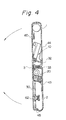
- Figs. 3 and 4 show the portable printer in an unfolded state for carrying, transportation or storage.
- the portable printer has two individual cases, namely, a first case 1 and a second case 2.
- the two cases 1 and 2 are hinged by hinges 3 so as to be able to turn relative to each other.
- the first case 1 contains a printing mechanism 10, a dry cell 50, and associated parts
- the second case 2 contains a sheet feed mechanism 20, a printed circuit board 30 provided with a control circuit, and associated parts.
- the printing mechanism 10 is contained in the first case 1.
- a flat platen 11 is placed in the first case 1, and a guide shaft 17 is fixedly placed so as to extend in parallel to the flat platen 11.
- a carriage 13 supported for a sliding movement on the guide shaft 17 is driven through a drive belt 16 by a spacing motor 15 for a reciprocation along the guide shaft 17.
- a print head 12 is mounted on the carriage 13 opposite to the platen 11, and a ribbon cassette 14 is detachably mounted on the carriage 13 so that an ink ribbon 14a travels between the platen 11 and the print head 12.
- the print head 12 supported opposite to the platen 11 travels along the platen 11 for printing characters.
- the sheet feed mechanism 20 is contained in the second case 2.
- Three pairs of sheet feed rollers 21 and 22 are supported respectively on rotary shafts 21a and 22a in the second case 2.
- the drive roller 21 is driven for rotation through a gear mechanism 26 by a line feed motor 24.
- the driven roller 22 is supported for rotation on arms 28 supported for turning on a shaft 27 in the second case 2.
- the arms 28 are pressed by springs 29 in the direction of an arrow A (see Fig. 2), to press the driven roller 22 against the driving roller 21.
- the arms 28 and the springs 29 are not shown in Fig. 3.
- the printed circuit board 30 fixedly provided within the second case 2 occupies a large space in the second case 2. Signals are transmitted through a flexible cable 31 to the spacing motor 15, the print head 12 and the line feed motor 24 from the control circuits formed on the printed circuit board 30.
- a main switch 45 of the portable printer is placed in a recess formed in the second case 2, so as to be positioned below the surface of the second case 2.
- the first case 1 and the second case 2 containing these mechanisms are hinged by the pair of hinges 3 at the opposite ends thereof, for a relative turning on the hinges 3 such that they are turned toward each other and away from each other.
- the portable printer When the portable printer is not used, namely, when carrying or transporting the portable printer, the portable printer can be opened through an angle of 180° so that the cases 1 and 2 extend in a plane as shown in Figs. 3, 4, and 5. Since the cases 1 and 2 have substantially the same thickness, the portable printer can be opened in a flat shape of a size corresponding to, for example, a size A4. Accordingly, the portable printer can be held under the arm or put in a bag, to facilitate carrying and transporting the same, and the portable printer can be stored in a narrow space. This state of the portable printer will be referred to the "unfolded state".
- a permanent magnet 32 is fixed to one of the outer side surfaces (bottom surfaces in the folded state in Fig. 2) of the cases 1 and 2 that face each other in the unfolded state, and a steel plate 33 is fixed to the other outer surface.
- the permanent magnet 32 attracts the steel plate 33, to hold the cases 1 and 2 in the unfolded state when the portable printer is unfolded.
- the portable printer can be folded by applying a force exceeding a certain level to the cases 1 and 2.
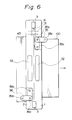
- Indicated at 35 and 36 are feet joined respectively to the bottom surfaces of the cases 1 and 2, i.e., the bottom surfaces in the folded state, so as to be turned through an angle of 90° (see Fig. 6).
- a sheet transporting passage 7 along which the print sheet 100 is transported is formed so as to extend straight through the cases 1 and 2 in the folded state.
- a sheet guide plate 43 is supported for turning on the second case 2 at the inlet of the sheet transporting passage 7. The sheet guide plate 43 can be opened to guide the print sheet 100 into the sheet transporting passage 7 for printing.
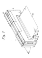
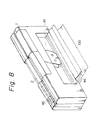
- the sheet transporting passage 7 extends straight and is inclined downstream with respect to the sheet transporting direction. Therefore, the print sheet 100 can be smoothly discharged through an outlet 5 formed in the first case 1 onto the surface 99 of a table (see Figs. 2 and 7).
- the sheet feed mechanism 20 transports the print sheet 100 along the sheet transporting passage 7, and the printing mechanism 10 prints characters on the print sheet 100.
- a lid 44 is pivotally supported at its lower end on the outer surface of the first case 1.
- the lid 44 is opened to expose the ribbon cassette 14 in a large opening formed in the first case 1, to facilitate replacing the ribbon cassette 14 with a new one.
- the outlet 5 is formed in the lower end of the lid 44.
- a permanent magnet 60 and a steel plate (magnetic member) 62 are fixed respectively to the respective wider outer surfaces 1a and 2a of the cases 1 and 2, which are contiguous with each other in the folded state as shown in Fig. 2.
- the permanent magnet 60 is placed in a recess 1b formed in the surface of the first case 1 and is attached to the first case 1.
- the permanent magnet 60 is positioned below the surface of the first case 1, to avoid a direct contact of the permanent magnet 60 with a magnetic recording medium, such as a cash card or a floppy disk, in the unfolded state.
- the steel plate 62 is placed in a recess 2b formed in the surface 2a of the second case 2 so as to be located opposite to the permanent magnet 60 in the folded state.
- the permanent magnet 60 attracts the steel plate 62.
- a stem 63 attached to the steel plate 62 is fitted loosely for axial movement in a hole formed in the central portion of the recess 2b of the second case 2.
- the extremity of the stem 63 is situated within the second case 2.
- a stem attached to a spring bearing plate 64 having a large diameter is fixedly joined to the extremity of the stem 63.
- a compression coil spring 65 having a comparatively small spring constant is extended between the spring bearing plate 64 and the second case 2, to bias the spring bearing plate 64, the stem 63 and the steel plate 62 integrally toward the interior of the second case 2.
- the permanent magnet 60 attracts the steel plate 62 against the resilience of the compression coil spring 65, so that the steel plate 62 projects from the surface of the second case 2.
- the cases 1 and 2 are allowed to freely turn on the hinges 3, away from each other.
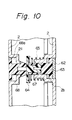
- Figs. 10 and 11 show a retaining device for an electronic apparatus in a second embodiment according to the present invention.
- This retaining device for an electronic apparatus is provided with a push button 68 that is operated by hand to forcibly push out a steel plate 62 from a recess 2b formed in a second case, against the resilience of a compression coil spring 65.
- the front end of the push button 68 is in contact with the back surface of a spring bearing plate 64, and when pushed, the push button 68 pushes the spring bearing plate 64 against the resilience of the compression coil spring 65.
- the head 68a of the push button 68 is placed in a recess 2c formed in the second case 2 opposite to the recess 2b so that the head 68a is positioned below the surface of the second case 2 and can be reached from the outside.
- the permanent magnet 60 is positioned well below the surface 1a of the first case 1, to thus prevent any possible leakage of the magnetic flux from the recess 1b, and the steel plate 62 is kept stable in the recess 2b below the surface 2a of the second case 2, as shown in Fig. 10.
- the permanent magnet 60 can not come into contact with the steel plate 62.
- the push bottom 68 is depressed with the finger tip to push the steel plate 62 forcibly out of the recess 2b to a point at which the steel plate 62 is brought into close contact with the permanent magnet 60 as shown in Fig. 11. Then, the steel plate 62 is attracted to the permanent magnet 60 and, consequently, the first case 1 and the second case 2 are fixed relative to each other.
- the rest of the parts and construction of the retaining device for an electronic apparatus in the second embodiment are the same as those of the retaining device for an electronic apparatus in the first embodiment.
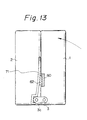
- Figure 12 and 13 show a third embodiment of the present invention.
- the third embodiment is provided with a cam 3c formed on the outer surface of a hinge 3, and a flat spring 71 fixedly holding a steel plate 62 and having a free end engaging the cam 3c.
- the flat spring 71 is provided within a second case 2. In the unfolded state, the free end of the flat spring 71 is pushed by the cam 3c, so that the flat spring 71 is strained in a large curvature to hold the steel plate 62 positioned below the surface of the second case 2 as shown in Fig. 12.
- a permanent magnet 60 is fixed to a first case so that the same is positioned below the surface of the first case 1.
- the steel plate 62 is projected from and retracted into the second case automatically, according to the movement of the second case 2 relative to the first case 1.
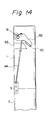
- Figures 14 and 15 show a fourth embodiment of the present invention.
- a movable arm 82 is supported pivotally in a first case 1 and is biased clockwise by a torsion spring 81.
- a permanent magnet 60 is secured to the free end of the movable arm 82.
- the permanent magnet 60 can be brought into contact with and separated from a yoke (magnetic member) 83 having one end exposed outside.
- an elongated rod 84 connected to a hinge 3 supports the movable arm 82, to keep the permanent magnet 60 separated from the yoke 83 as shown in Fig. 14 in the unfolded state. Accordingly, articles outside the first case 1 are not affected by the magnetic field of the permanent magnet 60 in the unfolded state.
- the rod 84 is pulled down as the hinge 3 turns and releases the movable arm 82. Then, the torsion spring 81 turns the movable arm 82 to bring the permanent magnet 60 into contact with the yoke 83 and, consequently, a steel plate 62 fixed to the second case 2 is attracted to the yoke 83 by the magnetism of the permanent magnet 60.
- the permanent magnet 60 provided within the first case 1 comes into contact with and separates from the yoke 83 according to the movement of the first case 1 relative to the second case 2. Therefore, in the unfolded state, articles outside the cases 1 and 2 are not affected by the magnetic field of the permanent magnet 60.
- the magnet and the magnetic member may be interchanged.
- the permanent magnet 60 must be positioned below the surface of the case 1 or 2 and, preferably, the steel plate 62 does not project from the surface of the case 2 or 1 in the unfolded state.
- the present invention is applicable to various electronic apparatuses including personal computers and word processors, as well as the portable printer.
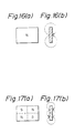
- each (b) is a side view thereof, respectively.
- the flat rectangular magnet of Fig. 16 has the usual magnet pole arrangement, the center portion of which has smaller magnetic attraction.
- the same shape of magnet of Fig. 17 has 4 magnetic poles on both sides. It is preferable to use the latter type rather than the former, as a smaller leakage of the magnetic flux from the recess occurs when the latter type is used.
- the retaining device for an electronic apparatus in accordance with the present invention fixes the plurality of cases relative to each other by the magnetic attraction of the magnet, and thus the retaining device for an electronic apparatus can be readily given a compact, lightweight and durable construction at a reduced cost. Since the magnet is positioned below the surface of the case, magnetic data recorded on a magnetic recording medium cannot be destroyed when the magnetic recording medium is brought into contact with the case.
Landscapes
- Engineering & Computer Science (AREA)
- Theoretical Computer Science (AREA)
- Computer Security & Cryptography (AREA)
- Microelectronics & Electronic Packaging (AREA)
- Computer Hardware Design (AREA)
- Power Engineering (AREA)
- Human Computer Interaction (AREA)
- Physics & Mathematics (AREA)
- General Engineering & Computer Science (AREA)
- General Physics & Mathematics (AREA)
- Casings For Electric Apparatus (AREA)
Applications Claiming Priority (2)
| Application Number | Priority Date | Filing Date | Title |
|---|---|---|---|
| JP8910/91 | 1991-01-29 | ||
| JP3008910A JPH05211399A (ja) | 1991-01-29 | 1991-01-29 | 小型電子機器の形態固定装置 |
Publications (3)
| Publication Number | Publication Date |
|---|---|
| EP0498556A2 true EP0498556A2 (fr) | 1992-08-12 |
| EP0498556A3 EP0498556A3 (en) | 1993-01-20 |
| EP0498556B1 EP0498556B1 (fr) | 1996-07-17 |
Family
ID=11705827
Family Applications (1)
| Application Number | Title | Priority Date | Filing Date |
|---|---|---|---|
| EP92300737A Expired - Lifetime EP0498556B1 (fr) | 1991-01-29 | 1992-01-29 | Dispositif de retenue pour appareils électroniques |
Country Status (4)
| Country | Link |
|---|---|
| US (1) | US5312144A (fr) |
| EP (1) | EP0498556B1 (fr) |
| JP (1) | JPH05211399A (fr) |
| DE (1) | DE69212173T2 (fr) |
Cited By (1)
| Publication number | Priority date | Publication date | Assignee | Title |
|---|---|---|---|---|
| US6272603B1 (en) | 1998-02-17 | 2001-08-07 | International Business Machines Corporation | Cache coherency protocol having hovering (H), recent (R), and tagged (T) states |
Families Citing this family (13)
| Publication number | Priority date | Publication date | Assignee | Title |
|---|---|---|---|---|
| US5409275A (en) * | 1991-03-19 | 1995-04-25 | Fujitsu Isotec Limited | Magnetic retaining device for electronic apparatus |
| US7089627B2 (en) * | 2001-04-23 | 2006-08-15 | L'oreal Usa, Inc. | Magnetic hinge and device including magnetically-attracted plates |
| BR0212705B1 (pt) * | 2001-08-21 | 2012-10-16 | dobradiça magnética definida por um eixo de dobradiça e estojo de cosméticos. | |
| US6935605B2 (en) | 2003-02-04 | 2005-08-30 | Tg3 Electronics Incorporated | Computer keyboard with release clip |
| US20050018393A1 (en) * | 2003-07-25 | 2005-01-27 | Uniwill Computer Corp. | Magnetic open/close structure for electronic device |
| TWI259350B (en) * | 2004-06-23 | 2006-08-01 | Quanta Comp Inc | Notebook computer and electronic device |
| US20060046792A1 (en) * | 2004-08-31 | 2006-03-02 | Hassemer Brian J | Hinge apparatus and methods therefor |
| JP2008165367A (ja) * | 2006-12-27 | 2008-07-17 | Toshiba Corp | 電子機器 |
| US20090100732A1 (en) * | 2007-10-19 | 2009-04-23 | Concept Workshop Worldwide, Llc | Magnetic display device |
| JP5029549B2 (ja) * | 2008-09-18 | 2012-09-19 | 富士通株式会社 | 電子機器 |
| TWI508648B (zh) * | 2013-10-15 | 2015-11-11 | Wistron Corp | 磁鐵固定結構及具有其之電子裝置 |
| CN206282205U (zh) * | 2016-05-31 | 2017-06-27 | 酷码科技股份有限公司 | 机箱装置及其盖板结构与举升机构 |
| CN114449070B (zh) * | 2020-11-05 | 2022-10-11 | 华为技术有限公司 | 可折叠电子设备 |
Family Cites Families (15)
| Publication number | Priority date | Publication date | Assignee | Title |
|---|---|---|---|---|
| DE1070061B (de) * | 1959-11-26 | Siemens-Electrogeräte Aktiengesellschaft, Berlin und München | Magnetverschjuß für Türen, Deckel oder Klappen | |
| US2219186A (en) * | 1938-11-02 | 1940-10-22 | Gen Electric | Magnetic latch |
| US2288688A (en) * | 1939-08-05 | 1942-07-07 | Dubilier William | Magnetic lock |
| US2475226A (en) * | 1945-02-01 | 1949-07-05 | Robert P Ellis | Magnetic fastener |
| US2586900A (en) * | 1949-11-02 | 1952-02-26 | Alderman Wayne | Magnetic door latch |
| US2693382A (en) * | 1951-03-17 | 1954-11-02 | Macy O Teetor | Magnetic door catch |
| US2690922A (en) * | 1952-01-29 | 1954-10-05 | Macy O Teetor | Magnetic catch for sliding doors |
| US2877041A (en) * | 1955-10-04 | 1959-03-10 | Gen Electric | Magnetic latch for refrigerator door |
| FR1180547A (fr) * | 1957-08-02 | 1959-06-04 | Chausson Usines Sa | Serrure magnétique, notamment pour portes battantes |
| FR1215185A (fr) * | 1958-11-08 | 1960-04-15 | Fermeture à aimant notamment pour porte étanche | |
| DE2438312A1 (de) * | 1974-08-09 | 1976-02-19 | Oberholz Soehne Paul | Schalldaempfende vorrichtung an magnetverschluessen, insbesondere fuer kuehl- und gefrierraumtueren |
| JPS5210105A (en) * | 1975-07-15 | 1977-01-26 | Kenkichi Tsukamoto | Moving coild cartidge |
| JPH0537514Y2 (fr) * | 1987-05-29 | 1993-09-22 | ||
| US4986417A (en) * | 1989-11-22 | 1991-01-22 | Nick Hsu | Structure of stationery case |
| JPH0434055U (fr) * | 1990-07-18 | 1992-03-19 |
-
1991
- 1991-01-29 JP JP3008910A patent/JPH05211399A/ja active Pending
-
1992
- 1992-01-29 EP EP92300737A patent/EP0498556B1/fr not_active Expired - Lifetime
- 1992-01-29 US US07/827,641 patent/US5312144A/en not_active Expired - Fee Related
- 1992-01-29 DE DE69212173T patent/DE69212173T2/de not_active Expired - Fee Related
Cited By (1)
| Publication number | Priority date | Publication date | Assignee | Title |
|---|---|---|---|---|
| US6272603B1 (en) | 1998-02-17 | 2001-08-07 | International Business Machines Corporation | Cache coherency protocol having hovering (H), recent (R), and tagged (T) states |
Also Published As
| Publication number | Publication date |
|---|---|
| JPH05211399A (ja) | 1993-08-20 |
| EP0498556B1 (fr) | 1996-07-17 |
| DE69212173D1 (de) | 1996-08-22 |
| US5312144A (en) | 1994-05-17 |
| DE69212173T2 (de) | 1996-11-21 |
| EP0498556A3 (en) | 1993-01-20 |
Similar Documents
| Publication | Publication Date | Title |
|---|---|---|
| US5409275A (en) | Magnetic retaining device for electronic apparatus | |
| EP0498556B1 (fr) | Dispositif de retenue pour appareils électroniques | |
| JP2857498B2 (ja) | ポータブルプリンタ | |
| JPH11105359A (ja) | 印刷装置およびカートリッジ | |
| US20060024114A1 (en) | Printer assembly and method of using the same | |
| JPS5915971A (ja) | エンドレスベルト状記録体を用いた記録装置 | |
| US8070154B2 (en) | Paper holding device and printer with the paper holding device | |
| KR920004918A (ko) | 전사/기록용지 카트리지와 기록장치 | |
| TW388864B (en) | Disk apparatus | |
| JP2005324535A (ja) | ペーパーローディング装置及びこれを備えたミニプリンタ | |
| JP3089043B2 (ja) | ビジネス機器用文書整合装置及びプリンタ用文書整合機構 | |
| JPH11139657A (ja) | 記録装置 | |
| CN115848026B (zh) | 印刷装置 | |
| KR970000607B1 (ko) | 인자장치 | |
| JP2663952B2 (ja) | ポータブルプリンタ | |
| JP4123107B2 (ja) | 媒体搬送機構および情報読取手段付きプリンタ | |
| JP4573996B2 (ja) | プリンタ付き携帯機器装置 | |
| JPH056132Y2 (fr) | ||
| JPH11227957A (ja) | 用紙カートリッジおよびプリンター | |
| JPH0310050Y2 (fr) | ||
| JPH0348669Y2 (fr) | ||
| JP3245275B2 (ja) | 原稿読取装置 | |
| KR100224990B1 (ko) | 컴팩트 디스크의 디스크 이송장치 | |
| JP2513666Y2 (ja) | リボンカセット | |
| JPH0620619Y2 (ja) | リボンカセットの装▲填▼機構 |
Legal Events
| Date | Code | Title | Description |
|---|---|---|---|
| PUAI | Public reference made under article 153(3) epc to a published international application that has entered the european phase |
Free format text: ORIGINAL CODE: 0009012 |
|
| AK | Designated contracting states |
Kind code of ref document: A2 Designated state(s): DE FR GB |
|
| PUAL | Search report despatched |
Free format text: ORIGINAL CODE: 0009013 |
|
| AK | Designated contracting states |
Kind code of ref document: A3 Designated state(s): DE FR GB |
|
| 17P | Request for examination filed |
Effective date: 19930428 |
|
| 17Q | First examination report despatched |
Effective date: 19941205 |
|
| GRAH | Despatch of communication of intention to grant a patent |
Free format text: ORIGINAL CODE: EPIDOS IGRA |
|
| GRAH | Despatch of communication of intention to grant a patent |
Free format text: ORIGINAL CODE: EPIDOS IGRA |
|
| GRAA | (expected) grant |
Free format text: ORIGINAL CODE: 0009210 |
|
| AK | Designated contracting states |
Kind code of ref document: B1 Designated state(s): DE FR GB |
|
| REF | Corresponds to: |
Ref document number: 69212173 Country of ref document: DE Date of ref document: 19960822 |
|
| ET | Fr: translation filed | ||
| PLBE | No opposition filed within time limit |
Free format text: ORIGINAL CODE: 0009261 |
|
| 26N | No opposition filed | ||
| PGFP | Annual fee paid to national office [announced via postgrant information from national office to epo] |
Ref country code: FR Payment date: 19980109 Year of fee payment: 7 |
|
| PGFP | Annual fee paid to national office [announced via postgrant information from national office to epo] |
Ref country code: GB Payment date: 19980120 Year of fee payment: 7 |
|
| PGFP | Annual fee paid to national office [announced via postgrant information from national office to epo] |
Ref country code: DE Payment date: 19980206 Year of fee payment: 7 |
|
| PG25 | Lapsed in a contracting state [announced via postgrant information from national office to epo] |
Ref country code: GB Free format text: LAPSE BECAUSE OF NON-PAYMENT OF DUE FEES Effective date: 19990129 |
|
| GBPC | Gb: european patent ceased through non-payment of renewal fee |
Effective date: 19990129 |
|
| PG25 | Lapsed in a contracting state [announced via postgrant information from national office to epo] |
Ref country code: FR Free format text: LAPSE BECAUSE OF NON-PAYMENT OF DUE FEES Effective date: 19990930 |
|
| PG25 | Lapsed in a contracting state [announced via postgrant information from national office to epo] |
Ref country code: DE Free format text: LAPSE BECAUSE OF NON-PAYMENT OF DUE FEES Effective date: 19991103 |
|
| REG | Reference to a national code |
Ref country code: FR Ref legal event code: ST |