EP0500400A2 - Apparat zum Messen der Dimensionen von Gegenständen - Google Patents
Apparat zum Messen der Dimensionen von Gegenständen Download PDFInfo
- Publication number
- EP0500400A2 EP0500400A2 EP92301562A EP92301562A EP0500400A2 EP 0500400 A2 EP0500400 A2 EP 0500400A2 EP 92301562 A EP92301562 A EP 92301562A EP 92301562 A EP92301562 A EP 92301562A EP 0500400 A2 EP0500400 A2 EP 0500400A2
- Authority
- EP
- European Patent Office
- Prior art keywords
- ccd camera
- image
- detecting
- coordinates
- view
- Prior art date
- Legal status (The legal status is an assumption and is not a legal conclusion. Google has not performed a legal analysis and makes no representation as to the accuracy of the status listed.)
- Withdrawn
Links
Images

Classifications
-
- G—PHYSICS
- G01—MEASURING; TESTING
- G01B—MEASURING LENGTH, THICKNESS OR SIMILAR LINEAR DIMENSIONS; MEASURING ANGLES; MEASURING AREAS; MEASURING IRREGULARITIES OF SURFACES OR CONTOURS
- G01B11/00—Measuring arrangements characterised by the use of optical techniques
- G01B11/002—Measuring arrangements characterised by the use of optical techniques for measuring two or more coordinates
Definitions
- This invention relates to an apparatus for measuring the dimensions of objects and more specifically to a high-precision object dimension measuring apparatus using a CCD camera.
- the dimensions of the opening in the die have conventionally been measured indirectly by measuring the cross-sectional dimensions of an extruded product.
- the object of this invention is to provide an object dimension measuring apparatus which mitigates the above-mentioned disadvantages.
- an object dimension measuring apparatus comprising:
- An object dimension measuring apparatus which embodies the present invention may, for example, consist of: a CCD camera mounted to an X- and a Y-axis table with its optical axis aligned with a Z-axis; a specimen table incorporating a light source and having its specimen mounting surface formed of a transparent member; a light diffusion plate mounted on the specimen; and a computer.
- the computer further comprising: a control means for moving a field of view of the CCD camera by using CAD data; a coordinate detecting means for detecting coordinates of the CCD camera's field of view on the X- and Y- axis table; an image processing means for processing output signals from the CCD camera; a intensity reversing point detecting means for detecting intensity reversing points on the image produced by the image processing means; a coordinate calculation means for calculating the coordinates of the intensity reversing points on the image; and a calculation means for calculating the dimensions of the specimen from a distance travelled by the CCD camera and x, y coordiantes of the image.
- This particular configuration makes it possible to measure with an accuracy of 1/100 mm the dimensions of an object too large to be taken in a single field of view of the CCD camera.
- reference numeral 1 represents a dimension measuring apparatus, which has an L-shaped frame 6 erected on a base 4 on which a specimen table 2 is mounted. Under the upper portion of the frame 6 are arranged an X-axis table 12 and a Y-axis table 14. On the Y-axis table 14 is mounted a CCD camera 18 that has a lens 16 whose optical axis 10 is aligned with a Z-axis.
- the specimen table 2 has a light source 20 installed therein and also a transparent plate 22 at the top, on which a specimen 24 is supported by a clamp not shown.
- a light diffusion plate 26 of semi-transparent material is placed on the specimen 24.
- the specimen 24 is a sample taken from aluminum extrusion products.
- Denoted 30 is a computer, which consists of: a control means using CAD data for moving the field of view of the CCD camera; a coordinate detection means for detecting the coordinates of the CCD camera's field of view on the X- and Y-axis table; an image processing means for processing output signals from the CCD camera; a intensity reversing point detecting means for detecting intensity reversing points on the image produced by the image processing means; a coordinate calculation means for calculating the coordinates of the intensity reversing points on the image; and a calculation means for determining the dimensions of the specimen from the distance traveled by the CCD camera and from the x and y coordinates of the image.
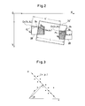
- the field of view 28 of the CCD camera 18 is moved, according to the CAD data, until the upper left corner of the viewing field comes to a point O a (X a , Y a ) on the X- and Y-axis table 12, 14. Then the left side portion of the shadow 24' of the specimen is photographed. The photographed image is bright in the left part.
- the upper left corner of the field of view 28 of the CCD camera 18 is moved to a point O b ( Xb , Y b ) on the X- and Y-axis table 12, 14 to take a picture of the right side portion of the specimen's shadow 24'. The photographed image is dark in the left part.
- a means for detecting the distance traveled by the origins O a , O b may employ various kinds of methods, such as one for converting the rotation of a ball screw into a distance signal by a rotary encoder, one for magnetically detecting the movement of a magnetic scale and converting it into pulse signals, or one for moving the X- and Y-axis table at a constant speed and reading the time traveled with a timer.
- This embodiment adopts the method of converting the rotation of the ball screw of X-Y table into the distance signal by the rotary encoder.
- the coordinates of the origin O a (X a , Y a ) and the origin O b (X b , Y b ) are read and the coordinate detection circuit in the computer 30 calculates the distance traveled by the CCD camera 18, i.e., the distance L' between the origins O a , O b .
- the intensity level detection circuit sorts the intensity output from each image-processed pixel into one of 256 levels (0-255) and produces a binary output - a "0" (representing a dark point) when the intensity falls in the 0-99 range and a "1" when it falls in the 100-255 range - to identify the intensity of each image.
- This circuit also scans each pixel to output their coordinate signals of (x a , y a ) and ( Xb , y b ) along with the binary signals. (In the following, suffix is omitted when general explanations are given.)
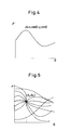
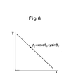
- the intensity reversing point detecting circuit which employs, for example, the Hough transform technique, samples a plurality of x, y coordinate data for the intensity reversing points (in this embodiment 17 samples) and calculates the distance p of each sampled value from the origin O and its angle 0 with respect to the x-axis according to a predetermined sequence.
- the principle of this process is explained by referring to Figure 3.
- the y-axis in Figure 3 is shown inverted with respect to the x-axis to present the ordinary x, y coordinates for better understanding.
Landscapes
- Physics & Mathematics (AREA)
- General Physics & Mathematics (AREA)
- Length Measuring Devices By Optical Means (AREA)
Applications Claiming Priority (2)
| Application Number | Priority Date | Filing Date | Title |
|---|---|---|---|
| JP3030231A JPH04269607A (ja) | 1991-02-25 | 1991-02-25 | 物体の寸法計測装置 |
| JP30231/91 | 1991-02-25 |
Publications (2)
| Publication Number | Publication Date |
|---|---|
| EP0500400A2 true EP0500400A2 (de) | 1992-08-26 |
| EP0500400A3 EP0500400A3 (en) | 1993-03-17 |
Family
ID=12297939
Family Applications (1)
| Application Number | Title | Priority Date | Filing Date |
|---|---|---|---|
| EP19920301562 Withdrawn EP0500400A3 (en) | 1991-02-25 | 1992-02-25 | Apparatus for measuring dimensions of objects |
Country Status (4)
| Country | Link |
|---|---|
| US (1) | US5481298A (de) |
| EP (1) | EP0500400A3 (de) |
| JP (1) | JPH04269607A (de) |
| NO (1) | NO920725L (de) |
Cited By (3)
| Publication number | Priority date | Publication date | Assignee | Title |
|---|---|---|---|---|
| WO2005036461A1 (en) | 2003-10-13 | 2005-04-21 | Koninklijke Philips Electronics N.V. | A method for measuring dimensions by means of a digital camera |
| EP1624279A1 (de) * | 2004-08-06 | 2006-02-08 | Axalto SA | System und Verfahren zur berührungslosen Erfassung der Abmessungen eines lichtundurchlässigen Objektes |
| CN104807403A (zh) * | 2015-04-23 | 2015-07-29 | 上海大学 | 一种用于大型工件尺寸测量的主动光测棒 |
Families Citing this family (17)
| Publication number | Priority date | Publication date | Assignee | Title |
|---|---|---|---|---|
| US5479683A (en) * | 1993-12-29 | 1996-01-02 | Bausch & Lomb Incorporated | Three-dimensional eyewinder apparatus |
| JPH0970780A (ja) * | 1995-09-06 | 1997-03-18 | Fanuc Ltd | ロボットのツール形状補正方式 |
| US5739913A (en) * | 1996-08-02 | 1998-04-14 | Mrs Technology, Inc. | Non-contact edge detector |
| US5841541A (en) * | 1996-12-31 | 1998-11-24 | Pitney Bowes Inc. | Apparatus and method for dimensional weighing utilizing a rotating sensor |
| JP3732335B2 (ja) * | 1998-02-18 | 2006-01-05 | 株式会社リコー | 画像入力装置及び画像入力方法 |
| US6878896B2 (en) * | 2002-07-24 | 2005-04-12 | United Parcel Service Of America, Inc. | Synchronous semi-automatic parallel sorting |
| US7063256B2 (en) * | 2003-03-04 | 2006-06-20 | United Parcel Service Of America | Item tracking and processing systems and methods |
| WO2004079546A2 (en) * | 2003-03-04 | 2004-09-16 | United Parcel Service Of America, Inc. | System for projecting a handling instruction onto a moving item or parcel |
| US7561717B2 (en) * | 2004-07-09 | 2009-07-14 | United Parcel Service Of America, Inc. | System and method for displaying item information |
| AU2004325542B2 (en) * | 2004-12-06 | 2008-08-21 | Memjet Technology Limited | Capping system for inkjet printers having arcuately moveable printheads |
| CN101881613A (zh) * | 2010-06-21 | 2010-11-10 | 邓丹 | 测量两点之间距离的方法 |
| CN104713486B (zh) * | 2015-03-20 | 2017-08-15 | 西安交通大学 | 一种合掌产品宽度在线检测装置及方法 |
| US10471478B2 (en) | 2017-04-28 | 2019-11-12 | United Parcel Service Of America, Inc. | Conveyor belt assembly for identifying an asset sort location and methods of utilizing the same |
| FR3068457B1 (fr) * | 2017-06-30 | 2019-08-16 | Lectra | Procede de determination d'une dimension entre le dos et le fil tranchant d'une lame vibrante montee sur un outil de coupe |
| CN111623709B (zh) * | 2020-07-17 | 2024-07-23 | 桂林量具刃具有限责任公司 | 一种可自动调整待测样品位置的图像测量仪及测量方法 |
| CN111780668A (zh) * | 2020-08-10 | 2020-10-16 | 昆山明益信智能设备有限公司 | 一种锦丝线3d位置度检测设备 |
| CN116242258B (zh) * | 2022-12-31 | 2025-08-01 | 捷威动力工业嘉兴有限公司 | 一种用于ccd视觉测量电池尺寸的方法 |
Family Cites Families (14)
| Publication number | Priority date | Publication date | Assignee | Title |
|---|---|---|---|---|
| US4310850A (en) * | 1980-07-21 | 1982-01-12 | Bethlehem Steel Corporation | Solid-state video camera having a video signal processor |
| JPS60194302A (ja) * | 1984-03-14 | 1985-10-02 | Toshiba Corp | 被写体計測装置 |
| JPS6252404A (ja) * | 1985-09-02 | 1987-03-07 | Nippon Steel Corp | 回転式寸法測定方法及び装置 |
| JPS6354000A (ja) * | 1986-08-22 | 1988-03-08 | 三洋電機株式会社 | 電子部品の位置検出装置 |
| JPS63134940A (ja) * | 1986-11-27 | 1988-06-07 | Canon Inc | パターン検査装置 |
| JPH01116402A (ja) * | 1987-10-30 | 1989-05-09 | Fuji Photo Film Co Ltd | 矩形シートの寸度測定方法及び装置 |
| GB8800570D0 (en) * | 1988-01-12 | 1988-02-10 | Leicester Polytechnic | Measuring method |
| JPH01213504A (ja) * | 1988-02-22 | 1989-08-28 | Tadao Totsuka | 光学的寸法測定装置 |
| DE3806686A1 (de) * | 1988-03-02 | 1989-09-14 | Wegu Messtechnik | Mehrkoordinatenmess- und -pruefeinrichtung |
| US4893183A (en) * | 1988-08-11 | 1990-01-09 | Carnegie-Mellon University | Robotic vision system |
| US5126569A (en) * | 1989-03-10 | 1992-06-30 | Massachusetts Institute Of Technology | Apparatus for measuring optical properties of materials |
| US4970653A (en) * | 1989-04-06 | 1990-11-13 | General Motors Corporation | Vision method of detecting lane boundaries and obstacles |
| JPH03209737A (ja) * | 1990-01-11 | 1991-09-12 | Tokyo Electron Ltd | プローブ装置 |
| US5136948A (en) * | 1990-10-31 | 1992-08-11 | Kabushiki Kaisha Shinkawa | Marking method and apparatus |
-
1991
- 1991-02-25 JP JP3030231A patent/JPH04269607A/ja active Pending
-
1992
- 1992-02-24 NO NO92920725A patent/NO920725L/no unknown
- 1992-02-25 EP EP19920301562 patent/EP0500400A3/en not_active Withdrawn
-
1995
- 1995-03-14 US US08/403,950 patent/US5481298A/en not_active Expired - Fee Related
Cited By (4)
| Publication number | Priority date | Publication date | Assignee | Title |
|---|---|---|---|---|
| WO2005036461A1 (en) | 2003-10-13 | 2005-04-21 | Koninklijke Philips Electronics N.V. | A method for measuring dimensions by means of a digital camera |
| CN100468456C (zh) * | 2003-10-13 | 2009-03-11 | 皇家飞利浦电子股份有限公司 | 通过数字照相机测量尺寸的方法 |
| EP1624279A1 (de) * | 2004-08-06 | 2006-02-08 | Axalto SA | System und Verfahren zur berührungslosen Erfassung der Abmessungen eines lichtundurchlässigen Objektes |
| CN104807403A (zh) * | 2015-04-23 | 2015-07-29 | 上海大学 | 一种用于大型工件尺寸测量的主动光测棒 |
Also Published As
| Publication number | Publication date |
|---|---|
| US5481298A (en) | 1996-01-02 |
| JPH04269607A (ja) | 1992-09-25 |
| NO920725L (no) | 1992-08-26 |
| NO920725D0 (no) | 1992-02-24 |
| EP0500400A3 (en) | 1993-03-17 |
Similar Documents
| Publication | Publication Date | Title |
|---|---|---|
| US5481298A (en) | Apparatus for measuring dimensions of objects | |
| Alexander et al. | Elimination of systematic error in subpixel accuracy centroid estimation [also Letter 34 (11) 3347-3348 (Nov1995)] | |
| US4650333A (en) | System for measuring and detecting printed circuit wiring defects | |
| US5774572A (en) | Automatic visual inspection system | |
| Lahajnar et al. | Machine vision system for inspecting electric plates | |
| US4945490A (en) | Brinell hardness indicator with digital readout | |
| EP1467176B1 (de) | System und Verfahren zur Inspektion | |
| US20030053045A1 (en) | System for inspecting a flat sheet workpiece | |
| EP0483362B1 (de) | Vorrichtung zur messung der blattlänge | |
| US7315383B1 (en) | Scanning 3D measurement technique using structured lighting and high-speed CMOS imager | |
| USRE38716E1 (en) | Automatic visual inspection system | |
| US12439024B2 (en) | Provision of real world and image sensor correspondence points for use in calibration of an imaging system for three dimensional imaging based on light triangulation | |
| EP1676238B1 (de) | Verfahren zur messung von abmessungen mittels einer digitalkamera | |
| Morishita et al. | Automated visual inspection systems for industrial applications | |
| KR20030053386A (ko) | 시시디 카메라를 이용한 치수측정 방법 | |
| KR0181993B1 (ko) | 레이저광을 이용한 물체의 외관치수측정장치 및 외관치수측정방법 | |
| RU2082084C1 (ru) | Способ ориентирования видеокамер при измерении геометрических параметров крупногабаритных объектов | |
| JPH0634325A (ja) | 回路基板パターンの寸法計測方法及び装置 | |
| KR100360374B1 (ko) | 카메라 이용시 발생하는 측정오차를 보상한 폭 측정장치 | |
| Warnecke et al. | Two-and three-dimensional linear measurement with image processing systems | |
| JPS60210745A (ja) | 視覚センサシステム | |
| El-Hakim | A stereo vision system for on-machine dimensional metrology | |
| USRE38559E1 (en) | Automatic visual inspection system | |
| JPH06241741A (ja) | リード検査装置 | |
| Ley et al. | Intelligent multisensor system for high-speed and high-precision 3D metrology |
Legal Events
| Date | Code | Title | Description |
|---|---|---|---|
| PUAI | Public reference made under article 153(3) epc to a published international application that has entered the european phase |
Free format text: ORIGINAL CODE: 0009012 |
|
| AK | Designated contracting states |
Kind code of ref document: A2 Designated state(s): BE DE DK ES FR GB IT SE |
|
| PUAL | Search report despatched |
Free format text: ORIGINAL CODE: 0009013 |
|
| AK | Designated contracting states |
Kind code of ref document: A3 Designated state(s): BE DE DK ES FR GB IT SE |
|
| 17P | Request for examination filed |
Effective date: 19930819 |
|
| 17Q | First examination report despatched |
Effective date: 19941031 |
|
| 18D | Application deemed to be withdrawn |
Effective date: 19950511 |