EP0501748A2 - Methode zur Fehlerkorrektur - Google Patents
Methode zur Fehlerkorrektur Download PDFInfo
- Publication number
- EP0501748A2 EP0501748A2 EP92301568A EP92301568A EP0501748A2 EP 0501748 A2 EP0501748 A2 EP 0501748A2 EP 92301568 A EP92301568 A EP 92301568A EP 92301568 A EP92301568 A EP 92301568A EP 0501748 A2 EP0501748 A2 EP 0501748A2
- Authority
- EP
- European Patent Office
- Prior art keywords
- data
- page
- recording unit
- error
- current page
- Prior art date
- Legal status (The legal status is an assumption and is not a legal conclusion. Google has not performed a legal analysis and makes no representation as to the accuracy of the status listed.)
- Withdrawn
Links
Images



Classifications
-
- G—PHYSICS
- G11—INFORMATION STORAGE
- G11B—INFORMATION STORAGE BASED ON RELATIVE MOVEMENT BETWEEN RECORD CARRIER AND TRANSDUCER
- G11B20/00—Signal processing not specific to the method of recording or reproducing; Circuits therefor
- G11B20/10—Digital recording or reproducing
- G11B20/18—Error detection or correction; Testing, e.g. of drop-outs
-
- H—ELECTRICITY
- H04—ELECTRIC COMMUNICATION TECHNIQUE
- H04N—PICTORIAL COMMUNICATION, e.g. TELEVISION
- H04N5/00—Details of television systems
- H04N5/76—Television signal recording
- H04N5/91—Television signal processing therefor
- H04N5/93—Regeneration of the television signal or of selected parts thereof
- H04N5/94—Signal drop-out compensation
- H04N5/945—Signal drop-out compensation for signals recorded by pulse code modulation
-
- G—PHYSICS
- G11—INFORMATION STORAGE
- G11B—INFORMATION STORAGE BASED ON RELATIVE MOVEMENT BETWEEN RECORD CARRIER AND TRANSDUCER
- G11B20/00—Signal processing not specific to the method of recording or reproducing; Circuits therefor
- G11B20/10—Digital recording or reproducing
- G11B20/18—Error detection or correction; Testing, e.g. of drop-outs
- G11B20/1876—Interpolating methods
Definitions
- This invention relates to an error concealing method of concealing uncorrectable errors when reproducing in a digital signal recording and reproducing apparatus.
- a digital signal recording and reproducing apparatus converting a video signal into a digital signal to record and reproduce it as the digital signal corrects errors generated when reproducing based on the error correcting parity added when recording.
- the digital signal recording and reproducing apparatus uses an error correcting code with a high capability and for example, in event when a large scar is formed on a tape or when trick plays are to be made such as slow and high speed play and the other, the reproducing error rate is extremely increased, resulting in remaining errors uncorrectable by the error correcting code. In such case, a detected error is subjected to an error concealment.
- Error concealment of a video signal is realized by a method of interpolating it from an adjacent data or substituting it with a data of one page before, or the like.
- one error may expansively influence on all blocks so that it becomes difficult to conceal it by interpolating from an adjacent data, and the error concealment is made by substituting it with a data of the corresponding block of one page before.
- variable length code is failed to be synchronized with a word due to error when decoding, which means that such one error may expansively influence on a plurality of blocks.
- an erroneous block has to be concealed. This means that a large-scale memory of one page or more is required for the concealment purpose after decoding of an encoded data.
- An object of this invention is to provide an error concealing method in which concealment is carried out under the bit rate reduction encoded condition so that a memory capacity necessary for concealment can be made small, degradation due to concealment can be decreased, and even after concealment, a variable length code can be properly decoded.
- an error concealing method of this invention features that an input sample value is blocked, and the data A and B which are respectively obtained by collecting the block thus obtained by blocking in a m by m blocks manner from one page having one field or a plurality of fields as a unit and being subjected to bit rate reduction encoding are divided into k recording blocks to be inserted thereinto, and when an error when reproducing in case of performing a record with said k recording blocks as one recording unit is to be concealed, an error position and data construction of the recording unit of a current page are compared with a data construction of the corresponding recording unit of the page of one page before said current page to determine a concealing method of each of said data A and B constituting the recording unit of said current page, and each of said data A and B of the recording unit of the current page is substituted with the data of the corresponding recording unit of the page of one page before said current page, thus an error concealment being achieved.
- one recording unit is formed of the data A and B which are subjected to bit rate reduction encoding and capable of being decoded independently thereby to perform recording.
- an error position and construction of the data A and B of the current page are compared with the construction of the data A and B of the corresponding recording unit of the page of one page before the current page to determine a concealing method of each of the data A and B, and each of them is substituted with the data of the corresponding recording unit one page before, thus an error concealment being realized.
- the error concealment under the bit rate reduction encoded condition makes it possible to decrease a memory capacity necessary for concealment, to reduce degradation due to concealment as well as to decode a variable length code properly even after concealment.
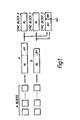
- Fig. 1 is a block diagram for explaining a construction method of three recording blocks X, Y and Z and a data construction.
- Fig. 2 is an explanatory drawing of an error concealing method according to a first embodiment of this invention.
- Fig. 3 is an explanatory drawing of an error concealing method according to a second embodiment of this invention.
- Fig. 4 is an explanatory drawing of an error concealing method according to a third embodiment of this invention.
- Fig. 5 is a block diagram of an error concealing apparatus for realizing an error concealing method of this invention.
- Fig. 6 is a block diagram of another error concealing apparatus for realizing an error concealing method of this invention.
- Fig. 7 is an explanatory drawing of an error concealing method according to a fourth embodiment of this invention.
- Fig. 8 is a block diagram of an error concealing apparatus for realizing the error concealing method of the fourth embodiment explained in Fig. 7.
- Fig. 9 is an explanatory drawing of a method of multiplexing a concealed information.
- Fig. 10 is an explanatory drawing of an error concealing method according to a fifth embodiment of this invention.
- Fig. 11 is an explanatory drawing of an error concealing method according to a sixth embodiment of this invention.
- Fig. 12 is an explanatory drawing of a method of multiplexing a concealed information.
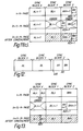
- Fig. 13 is an explanatory drawing of an error concealing method in case that a recording unit has a special construction.
- Fig. 1 illustrates an arrangement of three sync blocks X, Y and Z and a data construction.
- an input video signal is blocked
- data.A and B which are respectively obtained by collecting the block in a m by m blocks manner and being subjected to bit rate reduction encoding are divided into the three sync blocks X, Y and Z and inserted thereinto.
- bit rate reduction encoding an orthogonal transformation and variable length coding are used. That is, a blocked data is decomposed into frequency components by the orthogonal transformation and subjected to the variable length encoding successively in the order from the low frequency component.
- the data A and B are different in data amount in accordance with the information amount of each block, and the variable length encoding is controlled so that the data amount obtained by summing up those of the data A and B can become constantly equal to the total data amounts of the three sync blocks.
- the data corresponding to the low frequency component of the m blocks of the data a is inserted into the sync block X
- the data corresponding to the low frequency component of the m blocks of the data B is inserted into the sync block Y, which are expressed as AL and BL, respectively.
- the data of the data A and B remained not to be inserted into the sync blocks X and Y, that is, the data AH and BH corresponding to the high frequency components of the m blocks of the data A and B are inserted into the sync block Z, respectively.
- an address information (AD) is added at a predetermined position of the sync block Z so that the position where the data A and B are delimited can be clearly recognized when decoding because the sync block Z is made of the data AH and BH.
- the address information (AD) shows an address of delimiting the data AH and BH.
- the data AH and BH are discriminated in accordance with the address information AD, and respectively added to the data AL and BL to be decoded.
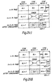
- Fig. 2 illustrates an error concealing method according to a first embodiment of this invention.
- Figs. 2(a) and (b) because an error is generated in the sync block X n+1 , only the data A is concealed.
- the data AL n+1 of the sync block X n+1 is substituted with the data AL n of the sync block X n
- the data AH n+1 of the sync block Z n+1 is substituted with the data AH n of the recording block Z.
- a n-th page and the (n+1)-th page are different in the address information AD from each other, but as the address information after concealment, an address information AD n+1 of the current page is adopted.
- the data A and B after concealment can be decoded perfectly.
- Fig. 3 illustrates an error concealing method according to a second embodiment of this invention.
- an error exists in the sync block Y n+1 , and only the data B is concealed.
- the data BL n+1 of the sync block Y n+1 is substituted with the BL n of the sync block Y n
- the BH n+1 of the sync block Z is substituted with the data BH n of the sync block Z.
- the address information after concealment the address information AD n of the page of one page before the current page is adopted.
- Fig. 4 illustrates an error concealing method according to a third embodiment of this invention.
- an error exists in the sync block Z n+1 , and the position where the error is existed is not clear, which means that it is not clear if the error is existed in the data A or the data B.
- the data A and B cannot be concealed, so that the data of all the sync blocks X n+1 , Y n+1 and Z n+1 are substituted with the data of the recording blocks X n , Y n and Z n in a respective manner.
- Fig.4(b) illustrates that an error exists in the sync block Z n+1 similar to the case of Fig.
- the position where the error is existed is possible to be discriminated. That is, the error can be discriminated to be existed in the data BH n+1 .
- the data BL n+1 of the sync block Y n+1 is substituted with the data BL n of the sync block Y n
- the data BH n+1 of the sync block Z n+1 is substituted with the data BH n of the sync block Z n .
- not only an error flag in the sync block unit but also an error flag in the data unit are required.
- Fig. 5 is a block diagram of an error concealing apparatus for realizing the error concealing methods shown above.
- the reference numeral 1 is a reproduced data
- 2 is an error flag showing that each sync block is erroneous
- 3 is a memory having a memory capacity of data amount for two pages
- 4 is a flag memory for the error flag
- 5 is an error detector for detecting an error in the recording unit
- 6 is an address information detector for detecting an address information (AD) in the recording unit
- 7 is an address information (AD n+1 ) of a current page in the recording unit
- 8 is an address information (AD n ) of the corresponding recording unit of the page of one page before the current page
- 9 is a concealing method determination circuit for determining a concealing method in response to the detected results of the detector 5 and the address information detector 6,
- 10 is a read controller for controlling reading the memory 3.
- the memory 3 has a capacity of data amount for two pages, and consists of two ranges each having a capacity of data amount for one page, one range of the two has the data of the current page having finished error correction and the other range of them has to the data of one page before the current page.
- concealing the data of the current page first, a sync block where an error is existed in the recording unit of the current page is detected by the error detector 5. Then, an address information multiplexed in the recording block Z for each of the current page and the page of one page before is detected by the address information detector 6. The error position and the address information thus detected by respective detectors are sent to the concealing method determination circuit 9 for determining a concealing method.
- the data is read out from the memory range of the current page, and if concealed, it is read out from the memory range of one page before the current page.
- Fig. 6 is a block diagram of another error concealing apparatus for realizing the error concealing methods already explained above.
- the reference numeral 100 is a memory having a memory capacity of data amount for three recording blocks
- 101 is a memory having a memory capacity of data amount for one page of sync block
- 102 is an address information detector for detecting an address information (AD) of the recording unit of the current page
- 103 is a write controller for controlling writing the data into the memory 101 in response to the result of the concealing method determination circuit 9.
- the memory 101 stores the data in every recording unit, and the detector 5 detects a position where an error is existed in response to an error flag 2 sent simultaneously with the data. Furthermore, the address information detector 102 detects an address information 7 multiplexed in the sync block Z. Then, the corresponding recording unit of one page before to the recording unit stored in the memory 100 is stored in the memory 101, so that a corresponding address information 8 of one page before is detected by the address information detector 6. The address information thus detected as above are sent to the concealing method determination circuit 9 for determining a concealing method. By controlling the write controller 103, if not concealed, the data is written into the memory, and if concealed, it is not written into the memory 101.
- Fig. 7 illustrates an error concealing method according to a fourth embodiment of this invention.
- the concealing method is determined by comparing the address information of the current page with the address information of the corresponding recording unit of one page before. That is, as shown in Fig. 7(a), if the difference in address between the current page and the page of one page before is small, the data loss of the high frequency component of the data AH n becomes small, and only the data A is concealed.
- Fig. 7(a) if the difference in address between the current page and the page of one page before is small, the data loss of the high frequency component of the data AH n becomes small, and only the data A is concealed.
- Fig. 8 is a block diagram of an error concealing apparatus for realizing the error concealing method shown in Fig. 7.
- the arrangement of the apparatus shown in Fig. 8 is similar basically to that shown in Fig. 5.
- an address comparator 200 is additively provided for comparing an address information of the recording unit of the current page with that of the corresponding recording unit of one page before.
- the address comparator 200 compares an address information (AD n+1 ) 7 of the recording unit of the current page and an address information (AD n ) 8 of the corresponding recording unit of one page before, and outputs a difference in address thus compared to a concealing method determination circuit 201.
- the concealing method determination circuit 201 switches the concealing method in response to the result obtained by the address comparator 200 and a predetermined threshold.
- the data loss of the high frequency component by concealment becomes small, and image quality degradation due to concealment can be made small.
- an information (concealment information) 300 showing the fact that concealment was made for the concealed recording block is additively provided to each sync block, so that the concealment information 300 can be made as a discrimination item for new concealment.
- Fig. 10 illustrates an error concealing method according to a fifth embodiment of this invention.
- the concealment has been already made in the past for the recording unit of the page of one page before the current page.
- an error exists in the sync block X.
- the recording unit of one page before has been already concealed in the past, so that the data of the high frequency component in the sync block Z may be already lost. That is, if concealment is made for only the data A of the current page, the data of the high frequency component will be further lost and image quality degradation may be made visible.
- all the data of one recording unit are concealed independently of the error position and the recording unit structure.
- Fig. 11 illustrates an error concealing method according to a sixth embodiment of this invention.
- explanations will be made on the concealment in a high speed play.
- a head traces across a plurality of tracks, so that the number of sync blocks to be reproduced properly will be small.
- it is required to use the data of the sync blocks which are reproduced properly in order to improve the image quality.
- the sync block is constructed such that one recording block is delimited into the low frequency component range and high frequency component range, so that when to be reproduced at high speed, if the sync blocks (sync block X and sync block Y) including the low frequency component are reproduced properly, an image on the screen can be reproduced with the low frequency component only.
- Fig. 11(a) shows a case when an error exists in the sync block X n+1 , and the data AL n+1 of the sync block X n+1 is substituted with the data AL n of the sync block X n .
- Fig. 11(a) shows a case when an error exists in the sync block X n+1 , and the data AL n+1 of the sync block X n+1 is substituted with the data AL n of the sync block X n .
- Fig. 11(a) shows a case when an error exists in the sync block X n+1 , and the data AL n+1 of the
- 11(b) shows a case when errors exist in the sync blocks X n+1 and Z n+1 , and the data AL n+1 of the sync block X n+1 is substituted with the data AL n of the sync block X n and the data AH n+1 of the sync block Z n+1 is substituted with the data AH n of the sync block Z n .
- an decoding information of each recording unit after concealment is defined as two bits as shown in Table 1.
- each recording unit is decoded based on the decoding information shown in Table 1.
- the decoding information is set as (O, 1).
- the data BH n is not to be decoded, and the decoding information is set as (1, 0).
- the decoding information 400 is multiplexed in each recording block as shown in Fig.
- the decoding can be properly made in the bit rate reduction decoding section.
- the decoding information after concealment is determined based on the error position in the current page and the decoding information of one page before. For example, in Fig. 11(c), the sync blocks Y n+1 and Z n+1 are concealed in the current page, and on the other hand, the decoding information of one page before is (1, 0), so that (1, 1) is set as the decoding information after concealment.
- the image on the screen can be made of the sync blocks including the low frequency component data reproduced when reproducing at high speed. Also, by defining the decoding information, the data can be properly decoded in the bit rate reduction decoding section.
- the above-described embodiments show such a case that the sync block Z consists of the data A and data B, however, in case that the data A and B are largely different in data amount from each other, for example, in case that the data amount of the data A is smaller than the data amount insertable into the sync block X as shown in Fig. 13, a part of the data B is inserted into the remaining range of the sync block X, and the sync block Z is made entirely of the data B. In such case, it is difficult to conceal the data A only, so that the whole of the recording unit is concealed.
Landscapes
- Engineering & Computer Science (AREA)
- Signal Processing (AREA)
- Multimedia (AREA)
- Signal Processing For Digital Recording And Reproducing (AREA)
Applications Claiming Priority (4)
| Application Number | Priority Date | Filing Date | Title |
|---|---|---|---|
| JP3030639A JPH04271071A (ja) | 1991-02-26 | 1991-02-26 | 誤り修整方法 |
| JP30639/91 | 1991-02-26 | ||
| JP275160/91 | 1991-10-23 | ||
| JP3275160A JPH05114251A (ja) | 1991-10-23 | 1991-10-23 | 誤り修整方法 |
Publications (2)
| Publication Number | Publication Date |
|---|---|
| EP0501748A2 true EP0501748A2 (de) | 1992-09-02 |
| EP0501748A3 EP0501748A3 (en) | 1993-11-10 |
Family
ID=26369025
Family Applications (1)
| Application Number | Title | Priority Date | Filing Date |
|---|---|---|---|
| EP19920301568 Withdrawn EP0501748A3 (en) | 1991-02-26 | 1992-02-25 | Error concealing method |
Country Status (3)
| Country | Link |
|---|---|
| US (1) | US5313471A (de) |
| EP (1) | EP0501748A3 (de) |
| KR (1) | KR920017085A (de) |
Cited By (2)
| Publication number | Priority date | Publication date | Assignee | Title |
|---|---|---|---|---|
| WO1998027742A1 (en) * | 1996-12-18 | 1998-06-25 | Thomson Consumer Electronics, Inc. | System for maintaining datastream continuity in the presence of disrupted source data |
| US6377628B1 (en) | 1996-12-18 | 2002-04-23 | Thomson Licensing S.A. | System for maintaining datastream continuity in the presence of disrupted source data |
Families Citing this family (11)
| Publication number | Priority date | Publication date | Assignee | Title |
|---|---|---|---|---|
| EP0595268B1 (de) | 1992-10-28 | 2001-03-21 | Victor Company Of Japan, Limited | Kodiervorrichtung und -verfahren mit variablen Übertragungsraten |
| JP2855067B2 (ja) * | 1992-11-28 | 1999-02-10 | 三星電子株式会社 | デジタルvcrの画像記録方法 |
| US5532837A (en) * | 1992-12-18 | 1996-07-02 | Matsushita Electric Industrial Co., Ltd. | Digital video signal processing apparatus |
| JPH06195896A (ja) * | 1992-12-28 | 1994-07-15 | Canon Inc | 記録再生装置、記録装置及び再生装置 |
| JPH0887840A (ja) * | 1994-09-16 | 1996-04-02 | Canon Inc | 再生装置及びデータ処理装置 |
| US5841598A (en) * | 1994-10-28 | 1998-11-24 | Olympus Optical Co., Ltd. | Information recording/reproducing apparatus and data processing method |
| US5926610A (en) * | 1995-11-15 | 1999-07-20 | Sony Corporation | Video data processing method, video data processing apparatus and video data recording and reproducing apparatus |
| US6622275B2 (en) * | 1998-09-12 | 2003-09-16 | Qualcomm, Incorporated | Method and apparatus supporting TDD/TTY modulation over vocoded channels |
| JP2004062950A (ja) * | 2002-07-25 | 2004-02-26 | Sony Corp | データ処理装置およびデータ処理方法、並びにプログラム |
| TWI386868B (zh) * | 2009-01-17 | 2013-02-21 | Himax Tech Ltd | 使用內容調適懲罰函數的移動偵測方法 |
| TWI403977B (zh) * | 2009-02-10 | 2013-08-01 | Himax Tech Ltd | 使用鄰近像素移動資訊的移動偵測方法 |
Family Cites Families (16)
| Publication number | Priority date | Publication date | Assignee | Title |
|---|---|---|---|---|
| JPS5661873A (en) * | 1979-10-25 | 1981-05-27 | Sony Corp | Digital video signal processor |
| JPS5877034A (ja) * | 1981-10-30 | 1983-05-10 | Hitachi Ltd | 記録方法 |
| US4517600A (en) * | 1982-05-17 | 1985-05-14 | Rca Corporation | Error concealment system using dropout severity information for selection of concealment method |
| JP2539353B2 (ja) * | 1984-10-05 | 1996-10-02 | 株式会社日立製作所 | Pcm信号再生方法及び装置 |
| CA1310112C (en) * | 1985-05-21 | 1992-11-10 | Takao Abe | Apparatus for decoding error correcting code |
| EP0232417B1 (de) * | 1985-10-02 | 1991-11-06 | Deutsche Thomson-Brandt GmbH | Verfahren zur korrektur von übertragungsfehlern |
| JPH0697792B2 (ja) * | 1985-12-13 | 1994-11-30 | パイオニア株式会社 | 映像信号再生装置 |
| JP2597987B2 (ja) * | 1986-02-08 | 1997-04-09 | ソニー株式会社 | ブロツク化伝送信号のデコード装置 |
| JP2522258B2 (ja) * | 1986-09-05 | 1996-08-07 | ソニー株式会社 | 信号処理装置 |
| JP3050553B2 (ja) * | 1988-04-08 | 2000-06-12 | ソニー株式会社 | データ再生装置 |
| EP0339589A3 (de) * | 1988-04-28 | 1992-01-02 | Sharp Kabushiki Kaisha | Orthogonales Transformationskodierungssystem für Bilddaten |
| JPH02198274A (ja) * | 1988-10-14 | 1990-08-06 | Fuji Photo Film Co Ltd | 画像データ圧縮記録装置 |
| JP2900385B2 (ja) * | 1988-12-16 | 1999-06-02 | ソニー株式会社 | フレーム化回路及び方法 |
| EP0408343B1 (de) * | 1989-07-13 | 1998-11-04 | Canon Kabushiki Kaisha | Kodierung- und Dekodierungsvorrichtung geeignet für das Kopieren von Daten |
| DE69031102T2 (de) * | 1989-08-29 | 1998-01-15 | Matsushita Electric Ind Co Ltd | Digitalvideosignalaufzeichnungs- und -wiedergabegerät |
| EP0482888B1 (de) * | 1990-10-25 | 1997-06-04 | Matsushita Electric Industrial Co., Ltd. | Aufzeichnungs- und Wiedergabegerät für Videosignale |
-
1992
- 1992-02-24 US US07/840,756 patent/US5313471A/en not_active Expired - Fee Related
- 1992-02-25 EP EP19920301568 patent/EP0501748A3/en not_active Withdrawn
- 1992-02-26 KR KR1019920002984A patent/KR920017085A/ko not_active Ceased
Cited By (2)
| Publication number | Priority date | Publication date | Assignee | Title |
|---|---|---|---|---|
| WO1998027742A1 (en) * | 1996-12-18 | 1998-06-25 | Thomson Consumer Electronics, Inc. | System for maintaining datastream continuity in the presence of disrupted source data |
| US6377628B1 (en) | 1996-12-18 | 2002-04-23 | Thomson Licensing S.A. | System for maintaining datastream continuity in the presence of disrupted source data |
Also Published As
| Publication number | Publication date |
|---|---|
| US5313471A (en) | 1994-05-17 |
| KR920017085A (ko) | 1992-09-26 |
| EP0501748A3 (en) | 1993-11-10 |
Similar Documents
| Publication | Publication Date | Title |
|---|---|---|
| US4559568A (en) | Apparatus for re-recording a digital signal on a record medium and for reproducing the same therefrom | |
| EP0155101B1 (de) | Verfahren und Anordnung zur magnetischen Aufzeichnung und Wiedergabe | |
| EP0149245B1 (de) | PCM-Daten-Aufzeichnungssystem | |
| EP0065365A2 (de) | Digitaler Fernsehapparat | |
| US5313471A (en) | Error concealing method | |
| CN1010134B (zh) | 用于记录和/或重放数字数据的方法和装置 | |
| US5060077A (en) | Reproduction apparatus having means for initializing flag memories during slow motion and freeze reproduction | |
| JPH07111815B2 (ja) | デイジタル信号記録方式 | |
| US4292684A (en) | Format for digital tape recorder | |
| GB2086691A (en) | Signal processing method for digital signals possibly containing errors | |
| US5446597A (en) | Apparatus for recording digital signals with associated auxiliary data | |
| EP0336424B1 (de) | Daten-Signal-Wiedergabegerät für eine Aufzeichnung mit Schrägspurabtastung | |
| KR100187543B1 (ko) | 디지탈 데이터 처리방법 | |
| US4491882A (en) | Disc players | |
| JP2811802B2 (ja) | 情報伝送装置 | |
| EP0420280A2 (de) | Gerät zur Wiedergabe von digitalen Informationssignalen für die Wiedergabe von digitalen Audiosignalen mit einer von der Wiedergabegeschwindigkeit abweichenden Aufnahmegeschwindigkeit | |
| US5276561A (en) | Apparatus for reproducing digital signal | |
| KR910003378B1 (ko) | 디지탈 신호 복조 및 재생장치 | |
| EP0500358A2 (de) | Signalverarbeitungsmethode in einem digital VTR | |
| JPH0449313B2 (de) | ||
| EP0410897B1 (de) | Gerät zur Wiedergabe von digitalen Signalen | |
| JP2540804B2 (ja) | デジタル信号記録再生装置 | |
| JPH05114251A (ja) | 誤り修整方法 | |
| JPH0125159B2 (de) | ||
| JPS6151348B2 (de) |
Legal Events
| Date | Code | Title | Description |
|---|---|---|---|
| PUAI | Public reference made under article 153(3) epc to a published international application that has entered the european phase |
Free format text: ORIGINAL CODE: 0009012 |
|
| AK | Designated contracting states |
Kind code of ref document: A2 Designated state(s): DE FR GB NL |
|
| PUAL | Search report despatched |
Free format text: ORIGINAL CODE: 0009013 |
|
| AK | Designated contracting states |
Kind code of ref document: A3 Designated state(s): DE FR GB NL |
|
| 18D | Application deemed to be withdrawn |
Effective date: 19940511 |