EP0507466A1 - Système empêchant le recul dans les pentes pour un véhicule à moteur - Google Patents
Système empêchant le recul dans les pentes pour un véhicule à moteur Download PDFInfo
- Publication number
- EP0507466A1 EP0507466A1 EP92302266A EP92302266A EP0507466A1 EP 0507466 A1 EP0507466 A1 EP 0507466A1 EP 92302266 A EP92302266 A EP 92302266A EP 92302266 A EP92302266 A EP 92302266A EP 0507466 A1 EP0507466 A1 EP 0507466A1
- Authority
- EP
- European Patent Office
- Prior art keywords
- exhaust port
- condition
- speed
- signal
- operative
- Prior art date
- Legal status (The legal status is an assumption and is not a legal conclusion. Google has not performed a legal analysis and makes no representation as to the accuracy of the status listed.)
- Granted
Links
- 239000012530 fluid Substances 0.000 claims abstract description 18
- 230000008859 change Effects 0.000 claims description 10
- 230000005540 biological transmission Effects 0.000 claims description 9
- 238000004891 communication Methods 0.000 claims description 2
- 230000010365 information processing Effects 0.000 claims description 2
- 238000012545 processing Methods 0.000 abstract description 5
- 230000000694 effects Effects 0.000 abstract description 4
- 238000005096 rolling process Methods 0.000 abstract description 4
- 230000008901 benefit Effects 0.000 description 3
- 238000010586 diagram Methods 0.000 description 3
- 230000001133 acceleration Effects 0.000 description 2
- 230000007423 decrease Effects 0.000 description 2
- 238000013461 design Methods 0.000 description 2
- 230000004044 response Effects 0.000 description 2
- 230000009471 action Effects 0.000 description 1
- 230000001174 ascending effect Effects 0.000 description 1
- 238000002485 combustion reaction Methods 0.000 description 1
- 230000000881 depressing effect Effects 0.000 description 1
- 230000000994 depressogenic effect Effects 0.000 description 1
- 239000007788 liquid Substances 0.000 description 1
- 230000009347 mechanical transmission Effects 0.000 description 1
- 230000007246 mechanism Effects 0.000 description 1
- 238000000034 method Methods 0.000 description 1
- 238000012544 monitoring process Methods 0.000 description 1
- 230000008569 process Effects 0.000 description 1
Images
Classifications
-
- B—PERFORMING OPERATIONS; TRANSPORTING
- B60—VEHICLES IN GENERAL
- B60T—VEHICLE BRAKE CONTROL SYSTEMS OR PARTS THEREOF; BRAKE CONTROL SYSTEMS OR PARTS THEREOF, IN GENERAL; ARRANGEMENT OF BRAKING ELEMENTS ON VEHICLES IN GENERAL; PORTABLE DEVICES FOR PREVENTING UNWANTED MOVEMENT OF VEHICLES; VEHICLE MODIFICATIONS TO FACILITATE COOLING OF BRAKES
- B60T7/00—Brake-action initiating means
- B60T7/12—Brake-action initiating means for automatic initiation; for initiation not subject to will of driver or passenger
- B60T7/122—Brake-action initiating means for automatic initiation; for initiation not subject to will of driver or passenger for locking of reverse movement
-
- B—PERFORMING OPERATIONS; TRANSPORTING
- B60—VEHICLES IN GENERAL
- B60T—VEHICLE BRAKE CONTROL SYSTEMS OR PARTS THEREOF; BRAKE CONTROL SYSTEMS OR PARTS THEREOF, IN GENERAL; ARRANGEMENT OF BRAKING ELEMENTS ON VEHICLES IN GENERAL; PORTABLE DEVICES FOR PREVENTING UNWANTED MOVEMENT OF VEHICLES; VEHICLE MODIFICATIONS TO FACILITATE COOLING OF BRAKES
- B60T11/00—Transmitting braking action from initiating means to ultimate brake actuator without power assistance or drive or where such assistance or drive is irrelevant
- B60T11/10—Transmitting braking action from initiating means to ultimate brake actuator without power assistance or drive or where such assistance or drive is irrelevant transmitting by fluid means, e.g. hydraulic
- B60T11/103—Transmitting braking action from initiating means to ultimate brake actuator without power assistance or drive or where such assistance or drive is irrelevant transmitting by fluid means, e.g. hydraulic in combination with other control devices
-
- B—PERFORMING OPERATIONS; TRANSPORTING
- B60—VEHICLES IN GENERAL
- B60W—CONJOINT CONTROL OF VEHICLE SUB-UNITS OF DIFFERENT TYPE OR DIFFERENT FUNCTION; CONTROL SYSTEMS SPECIALLY ADAPTED FOR HYBRID VEHICLES; ROAD VEHICLE DRIVE CONTROL SYSTEMS FOR PURPOSES NOT RELATED TO THE CONTROL OF A PARTICULAR SUB-UNIT
- B60W10/00—Conjoint control of vehicle sub-units of different type or different function
- B60W10/04—Conjoint control of vehicle sub-units of different type or different function including control of propulsion units
- B60W10/06—Conjoint control of vehicle sub-units of different type or different function including control of propulsion units including control of combustion engines
-
- B—PERFORMING OPERATIONS; TRANSPORTING
- B60—VEHICLES IN GENERAL
- B60W—CONJOINT CONTROL OF VEHICLE SUB-UNITS OF DIFFERENT TYPE OR DIFFERENT FUNCTION; CONTROL SYSTEMS SPECIALLY ADAPTED FOR HYBRID VEHICLES; ROAD VEHICLE DRIVE CONTROL SYSTEMS FOR PURPOSES NOT RELATED TO THE CONTROL OF A PARTICULAR SUB-UNIT
- B60W10/00—Conjoint control of vehicle sub-units of different type or different function
- B60W10/18—Conjoint control of vehicle sub-units of different type or different function including control of braking systems
-
- B—PERFORMING OPERATIONS; TRANSPORTING
- B60—VEHICLES IN GENERAL
- B60W—CONJOINT CONTROL OF VEHICLE SUB-UNITS OF DIFFERENT TYPE OR DIFFERENT FUNCTION; CONTROL SYSTEMS SPECIALLY ADAPTED FOR HYBRID VEHICLES; ROAD VEHICLE DRIVE CONTROL SYSTEMS FOR PURPOSES NOT RELATED TO THE CONTROL OF A PARTICULAR SUB-UNIT
- B60W30/00—Purposes of road vehicle drive control systems not related to the control of a particular sub-unit, e.g. of systems using conjoint control of vehicle sub-units
- B60W30/18—Propelling the vehicle
- B60W30/18009—Propelling the vehicle related to particular drive situations
- B60W30/18109—Braking
- B60W30/18118—Hill holding
-
- B—PERFORMING OPERATIONS; TRANSPORTING
- B60—VEHICLES IN GENERAL
- B60W—CONJOINT CONTROL OF VEHICLE SUB-UNITS OF DIFFERENT TYPE OR DIFFERENT FUNCTION; CONTROL SYSTEMS SPECIALLY ADAPTED FOR HYBRID VEHICLES; ROAD VEHICLE DRIVE CONTROL SYSTEMS FOR PURPOSES NOT RELATED TO THE CONTROL OF A PARTICULAR SUB-UNIT
- B60W2510/00—Input parameters relating to a particular sub-units
- B60W2510/02—Clutches
- B60W2510/0208—Clutch engagement state, e.g. engaged or disengaged
-
- B—PERFORMING OPERATIONS; TRANSPORTING
- B60—VEHICLES IN GENERAL
- B60W—CONJOINT CONTROL OF VEHICLE SUB-UNITS OF DIFFERENT TYPE OR DIFFERENT FUNCTION; CONTROL SYSTEMS SPECIALLY ADAPTED FOR HYBRID VEHICLES; ROAD VEHICLE DRIVE CONTROL SYSTEMS FOR PURPOSES NOT RELATED TO THE CONTROL OF A PARTICULAR SUB-UNIT
- B60W2510/00—Input parameters relating to a particular sub-units
- B60W2510/06—Combustion engines, Gas turbines
- B60W2510/0604—Throttle position
-
- B—PERFORMING OPERATIONS; TRANSPORTING
- B60—VEHICLES IN GENERAL
- B60W—CONJOINT CONTROL OF VEHICLE SUB-UNITS OF DIFFERENT TYPE OR DIFFERENT FUNCTION; CONTROL SYSTEMS SPECIALLY ADAPTED FOR HYBRID VEHICLES; ROAD VEHICLE DRIVE CONTROL SYSTEMS FOR PURPOSES NOT RELATED TO THE CONTROL OF A PARTICULAR SUB-UNIT
- B60W2520/00—Input parameters relating to overall vehicle dynamics
- B60W2520/10—Longitudinal speed
-
- Y—GENERAL TAGGING OF NEW TECHNOLOGICAL DEVELOPMENTS; GENERAL TAGGING OF CROSS-SECTIONAL TECHNOLOGIES SPANNING OVER SEVERAL SECTIONS OF THE IPC; TECHNICAL SUBJECTS COVERED BY FORMER USPC CROSS-REFERENCE ART COLLECTIONS [XRACs] AND DIGESTS
- Y10—TECHNICAL SUBJECTS COVERED BY FORMER USPC
- Y10S—TECHNICAL SUBJECTS COVERED BY FORMER USPC CROSS-REFERENCE ART COLLECTIONS [XRACs] AND DIGESTS
- Y10S188/00—Brakes
- Y10S188/02—Hill holder
Definitions
- This invention relates generally to a motor vehicle hill holder system and more particularly to a system that in one embodiment is operative to maintain the motor vehicle brakes in an engaged condition so long as a selected speed condition such as vehicle land speed is below a predetermined value and in another embodiment combines the selected speed condition with one or more drive train conditions such as throttle and clutch positions to control actuation of the brakes.
- a selected speed condition such as vehicle land speed is below a predetermined value
- combines the selected speed condition with one or more drive train conditions such as throttle and clutch positions to control actuation of the brakes is partially described and may be used in conjunction with my copending application serial number 600,657 filed October 22, 1990 and entitled" Automatic Mechanical Transmission Start Control System".
- a variety of hill holder systems have been proposed in the past to automatically brake a vehicle descending a hill or to prevent a vehicle from rolling backwards while ascending a hill when the vehicle is traveling below some predetermined minimum speed value.
- Such can be of particular advantage to the vehicle driver in instances where the vehicle is a truck carrying a heavy load.
- the hill holder device includes a undirectional sprag clutch that , when actuated, permits the drive shaft to rotate in only one direction thus preventing it from rotating in an opposite direction in the event that the vehicle begins to roll backwards down an incline.
- the present invention employs a relatively simple fluid control valve arrangement that is responsive to a control signal derived from a selected speed condition signal alone or in combination with a selected drive train condition such as a throttle position and/or clutch position so as to cause the brakes to automatically engage when the control signal is below a predetermined value.
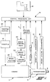
- an embodiment of the hill holder system is applied to a motor vehicle driven by an internal combustion engine 2.
- the speed of engine 2 is controlled by a throttle 18 whose position is sensed by sensor 20.
- Engine 2 is operatively connected to the vehicle's transmission 4 by clutch 6.
- Engine 2 is operative to rotate drive shaft 8 when clutched to transmission 4 and the rotary speed and direction of shaft 8 is governed by the gear combinations selected by selector 12.
- the hill holder system of the invention includes at least one speed sensor operative to sense and provide a signal indicative of a selected speed condition such as one or more of ground speed, engine speed, change in ground speed, and change in engine speed.
- Ground speed can be deduced for example from either transmission input speed sensor 14 or a transmission output speed sensor 16 and engine speed can for example, be sensed by monitoring the main drive shaft RPM such as by engine speed sensor 19 diagrammatrically shown in FIGURE 1.
- the hill holder system of the invention preferably includes a brake position sensor such as referenced by numeral 23 in FIGURE 1 that is operative to provide a signal indicating whether the vehicle brakes 25 are in an engaged or disengaged condition.
- the hill holder system of the invention also preferably includes a clutch position sensor 17 operative to provide a clutch position signal indicating whether the clutch is in an engaged or disengaged condition.
- Brakes 25 are operated by pressurized fluid such as air or a suitable liquid brake fluid that is conveyed under pressure from brake valve 24 to respective wheel brake cylinders (not shown) that are mechanically linked to the brakes and operative to move the brakes into engagement when pressurized as is well known to those skilled in the art of vehicle brake design.
- pressurized fluid such as air or a suitable liquid brake fluid that is conveyed under pressure from brake valve 24 to respective wheel brake cylinders (not shown) that are mechanically linked to the brakes and operative to move the brakes into engagement when pressurized as is well known to those skilled in the art of vehicle brake design.
- brake valve 24 has at least one exhaust port 27 that is normally closed when the brakes are engaged and normally open when the brakes are disengaged.
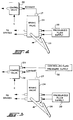
- Brake valve 24 receives pressurized fluid from a pressurized fluid supply 30 and is operative to enable the pressurized fluid to be delivered to the brake cylinders when pedal 26 is pressed in a clockwise direction as viewed in FIGURES 2 and 3 whilst exhaust port 27 is closed.
- exhaust port 27 opens to enable fluid pressure to decrease to ambient which in turn decreases pressure in the wheel brake cylinders to ambient enabling release of the brakes characteristically by return spring action, as is well known to those skilled in the art of vehicle wheel brake design.
- the system of the present invention employs a control valve 22 that is operatively connected to exhaust port 27 and is operative to control whether pressurized fluid is able to exhaust from port 27 in response to a control signal "C" hereinafter described.
- Control signal C is an output signal provided by control processing unit 10 shown in FIGURE 1.
- Control signal C is preferably an electrical signal that is delivered to brake control valve 22.
- Control signal C is a signal that in one embodiment of the invention is a function of speed derived from a selected speed condition such as vehicle ground speed from either transmission input speed 14 or transmission output speed 16 as previously described.
- control signal C is based upon a ground speed it may also be derived from other sources on the vehicle that in one way or another or correlatable to ground speed such as directly from the speedometer itself or from tire RPM.
- the speed condition signal can be sensed from a change in ground and/or engine speed as well as from ground and/or engine speed where such is desired.
- Achange in ground speed and/or engine RPM is characteristically indicative of increased load while undergoing acceleration which the system of the invention can then employ to automatically release the brakes while undergoing an acceleration and vice versa while undergoing a deceleration so as to automatically apply the brakes when the selected speed signal is below the predetermined value.
- Brake control valve 22 is preferably an electrical solenoid actuated valve that receives control signal C and is operative to close exhaust port 27 of valve 24 when, for example, the vehicle speed is below a predetermined value such as 3 miles per hour.
- Brake valve 24 receives pressurized fluid from supply 30 and, while exhaust port 27 remains closed, pressure is unable to bleed off of the brake cylinders and the brakes remain in the engaged condition regardless of whether the operator releases foot pedal 26 shown in FIGURES 2 and 3.
- control signal C instructs control valve 22 to open exhaust port 27 enabling pressure to bleed from the brake cylinders causing the brakes to release enabling the operator to accelerate by depressing or actuating the throttle which itself can be used to advantage as shown in FIGURE 1, where a throttle position sensor 20 is employed to provide processing unit 10 with information concerning the position of throttle 18 in combination with a selected speed condition alone and/or in combination with clutch position as previously described.
- unit 10 processes the information in combination with the selected speed condition and sends a control signal C instructing control valve 22 to open so as to enable pressure bleed off from brake valve 24 for release of brake 25.
- control signal C is operative to instruct control valve 22 to open exhaust port 27 of brake valve 24 to disengage the brakes when the speed condition signal has increased sufficiently to reach the predetermined value such as when the throttle is advanced or the clutch is engaged while the speed signal is below the predetermined value.
- FIGURE 3 shows a variation of the system of the invention in which a control valve 28 is operative to receive control signal C and close exhaust port 27 of brake valve 24 when, for example, vehicle ground speed is below a predetermined value so as to keep the brakes engaged as previously described.
- Control valve 28 differs from control valve 22 of FIGURE 2 in that it includes an additional input port 29 connected to a controlled fluid pressure supply source 32.
- Control signal C is operative to effect fluid communication between valve 28 and source 32 to enable valve 28 to receive controlled fluid pressure from fluid supply 32 and to control the rate at which control valve 28 is able to open exhaust port 27 of brake valve 24.
- control valve 28 may be operative to drive a piston or the like to open and close a port that in turn enables exhaust to pass from exhaust port 27 or stop it, as the case may be.
- Fluid supply 32 may, for example, be is exposed to the opposite side of the cylinder head and operate to control the rate at which the exhaust port is opened which in turn controls the rate at which the brakes are released.
- control signal C can be used to open the brake valve exhaust port to enable manual braking on operator when the selected speed condition signal is above a predetermined value.
- control signal C may be employed to change a condition of the exhaust port such as hereinbefore described with respect to FIGURE 3 so that the brakes are maintained in a engaged condition, including the level of engagement, so long as the speed signal remains below the predetermined value.
- control signal C is operative to open the exhaust port to disengage the brakes when the speed signal has increased sufficiently to reach the predetermined value.
- drive train conditions such as throttle position and/or clutch position signals may be processed in combination with the speed condition signal to effect engagement or disengagement of the brakes in the manner desired such as where the brakes are caused to disengage when the throttle is advanced and or the clutch is engaged even through the speed condition signal is below the predetermined value.
- the system of the invention employs a control valve responsive to a control signal that is operative to open and close the brake valve exhaust port(s) (may be more than one) according to whether the selected speed condition is above or below a predetermined value. Once below that value, the control valve operates to close the brake exhaust port(s) and maintain the brakes in an engaged condition to prevent the vehicle from rolling backward down an incline or to automatically brake the vehicle when descending an incline.
- combinations of selected drive train conditions such as throttle and clutch position may be processed with the selected speed condition signal to effect braking in the manner desired and the hill holder system of the invention does not in any manner prevent an operator from pressing on the brakes at anytime to override the system when desired.
Landscapes
- Engineering & Computer Science (AREA)
- Transportation (AREA)
- Mechanical Engineering (AREA)
- Chemical & Material Sciences (AREA)
- Combustion & Propulsion (AREA)
- Automation & Control Theory (AREA)
- Control Of Driving Devices And Active Controlling Of Vehicle (AREA)
- Control Of Throttle Valves Provided In The Intake System Or In The Exhaust System (AREA)
- Control Of Vehicle Engines Or Engines For Specific Uses (AREA)
Applications Claiming Priority (2)
| Application Number | Priority Date | Filing Date | Title |
|---|---|---|---|
| US679989 | 1991-04-03 | ||
| US07/679,989 US5137127A (en) | 1991-04-03 | 1991-04-03 | Motor vehicle hill holder system |
Publications (2)
| Publication Number | Publication Date |
|---|---|
| EP0507466A1 true EP0507466A1 (fr) | 1992-10-07 |
| EP0507466B1 EP0507466B1 (fr) | 1996-01-03 |
Family
ID=24729200
Family Applications (1)
| Application Number | Title | Priority Date | Filing Date |
|---|---|---|---|
| EP92302266A Expired - Lifetime EP0507466B1 (fr) | 1991-04-03 | 1992-03-16 | Système empêchant le recul dans les pentes pour un véhicule à moteur |
Country Status (3)
| Country | Link |
|---|---|
| US (1) | US5137127A (fr) |
| EP (1) | EP0507466B1 (fr) |
| DE (1) | DE69207249T2 (fr) |
Cited By (10)
| Publication number | Priority date | Publication date | Assignee | Title |
|---|---|---|---|---|
| WO1995011148A1 (fr) * | 1993-10-22 | 1995-04-27 | Automotive Products Plc | Systeme de commande d'antirecul |
| FR2713573A1 (fr) * | 1993-12-14 | 1995-06-16 | Renault | Procédé et dispositif de commande d'un actionneur de frein de roue d'un véhicule automobile en pente. |
| EP0995654A1 (fr) * | 1998-10-20 | 2000-04-26 | Volkswagen Aktiengesellschaft | Méthode et dispositif pour arrêter un véhicule soumis à une force |
| WO2003011663A1 (fr) * | 2001-07-21 | 2003-02-13 | Zf Friedrichshafen Ag | Prevention du roulage arriere dans un vehicule |
| EP1357006A1 (fr) * | 2002-04-26 | 2003-10-29 | Renault s.a.s. | Procédé et dispositif équivalent d'optimisation à l'arret du serrage des freins d'un véhicule automobile |
| WO2004033244A1 (fr) * | 2002-10-02 | 2004-04-22 | Volkswagen Aktiengesellschaft | Procede de commande d'un systeme d'entrainement et systeme d'entrainement |
| EP1526051A3 (fr) * | 2003-10-23 | 2005-08-31 | Scania CV AB | Procédé, dispositif et programme informatique pour commander un frein anti-recul |
| US7226389B2 (en) | 2002-12-30 | 2007-06-05 | Volvo Lastvagnar Ab | Method and device for hill start |
| CN101497335B (zh) * | 2008-01-24 | 2013-09-18 | 伊顿公司 | 主制动器坡起辅助系统和控制该系统的方法 |
| CN107176061A (zh) * | 2017-05-08 | 2017-09-19 | 中车大连电力牵引研发中心有限公司 | 车辆控制方法及装置 |
Families Citing this family (11)
| Publication number | Priority date | Publication date | Assignee | Title |
|---|---|---|---|---|
| DE19525552A1 (de) * | 1995-07-13 | 1997-01-16 | Teves Gmbh Alfred | Verfahren und Anordnung zum Halten eines Fahrzeugs auf geneigter Fahrbahn |
| IT1288799B1 (it) * | 1996-11-05 | 1998-09-24 | Magneti Marelli Spa | Sistema di controllo dello stazionamento e della partenza in pendenza di un autoveicolo. |
| US6162146A (en) * | 1999-04-28 | 2000-12-19 | Caterpillar Inc. | Electrohydraulic control device for a drive train of a machine |
| BR0110807A (pt) * | 2000-05-17 | 2003-02-11 | Luk Lamellen & Kupplungsbau | Processo e dispositivo para o acionamento automático de um freio de veìculo |
| DE10244024A1 (de) * | 2002-09-21 | 2004-04-01 | Zf Friedrichshafen Ag | Verfahren und Vorrichtung zum Verhindern eines unbeabsichtigten Wegrollens eines stillstehenden Fahrzeuges |
| AU2013231924B2 (en) | 2012-03-16 | 2017-04-20 | Allison Transmission, Inc. | Device and method for controlling transmission torque to provide hill ascent and/or descent assistance |
| IN2014DN08347A (fr) * | 2012-03-16 | 2015-05-08 | Allison Transm Inc | |
| US8845492B2 (en) | 2012-05-30 | 2014-09-30 | Cummins Inc. | Engine control override systems and methods |
| JP5727987B2 (ja) * | 2012-11-01 | 2015-06-03 | 日信工業株式会社 | 車両用ブレーキ制御装置 |
| JP2017114244A (ja) * | 2015-12-22 | 2017-06-29 | ローベルト ボッシュ ゲゼルシャフト ミット ベシュレンクテル ハフツング | 制御装置及び制御方法 |
| US12252105B2 (en) * | 2020-12-14 | 2025-03-18 | Ford Global Technologies, Llc | Hill-hold assist |
Citations (6)
| Publication number | Priority date | Publication date | Assignee | Title |
|---|---|---|---|---|
| DE3606035A1 (de) * | 1985-02-26 | 1986-08-28 | Akebono Brake Industry Co., Ltd., Tokio/Tokyo | Hydraulisches bremssystem fuer ein fahrzeug |
| DE3618532A1 (de) * | 1985-06-03 | 1986-12-04 | Nissan Motor Co., Ltd., Yokohama, Kanagawa | Anfahrhilfe fuer ein fahrzeug fuer das anfahren an einer steigung und verfahren zum steuern der anfahrhilfe |
| GB2192034A (en) * | 1986-06-26 | 1987-12-31 | Isuzu Motors Ltd | Apparatus for controlling the braking force on a vehicle |
| EP0251156A2 (fr) * | 1986-06-24 | 1988-01-07 | Adam Opel Aktiengesellschaft | Dispositif de freinage pour véhicule à moteur |
| EP0392732A1 (fr) * | 1989-04-14 | 1990-10-17 | Eaton Corporation | Dispositif de commande de démarrage pour une transmission mécanique automatique |
| US4967560A (en) * | 1988-10-28 | 1990-11-06 | Jidosha Kiki Co., Ltd. | Parking sustainer employing liquid pressure booster |
Family Cites Families (14)
| Publication number | Priority date | Publication date | Assignee | Title |
|---|---|---|---|---|
| US3768875A (en) * | 1970-09-25 | 1973-10-30 | Bendix Corp | Adaptive control for fluid pressure braking system |
| US3677609A (en) * | 1970-09-25 | 1972-07-18 | Bendix Corp | Adaptive control for fluid pressure braking system |
| US3740104A (en) * | 1971-08-02 | 1973-06-19 | L Wolf | Fluid brake system with skid control |
| US4061404A (en) * | 1976-12-06 | 1977-12-06 | The B. F. Goodrich Company | Brake pressure control valve |
| US4497395A (en) * | 1981-05-22 | 1985-02-05 | Toyota Jidosha Kabushiki Kaisha | Anti creep vehicle braking system allowing further additional braking action application |
| JPS5861349A (ja) * | 1981-10-06 | 1983-04-12 | Mitsubishi Motors Corp | 車両用自動変速機 |
| GB8400698D0 (en) * | 1984-01-11 | 1984-02-15 | Automotive Prod Plc | Motor vehicle transmission |
| US4582184A (en) * | 1984-04-02 | 1986-04-15 | Allied Corporation | Brake control device |
| US4667471A (en) * | 1984-08-20 | 1987-05-26 | Allied Corporation | Brake booster for vehicular hill holder system |
| SE445629B (sv) * | 1984-11-23 | 1986-07-07 | Volvo Ab | Hjelpanordning vid fordonsstart i backe |
| US4708406A (en) * | 1985-10-04 | 1987-11-24 | Nippondenso Co., Ltd. | Hydraulic braking system with malfunction alarm junction |
| JPS63166643A (ja) * | 1986-12-27 | 1988-07-09 | Isuzu Motors Ltd | 車両の制動力保持装置 |
| GB8812360D0 (en) * | 1988-05-25 | 1988-06-29 | Lucas Ind Plc | Fluid control device & braking system |
| US4867291A (en) * | 1988-06-28 | 1989-09-19 | Dana Corporation | Vehicle transmission hill holder with releasable one way clutch |
-
1991
- 1991-04-03 US US07/679,989 patent/US5137127A/en not_active Expired - Lifetime
-
1992
- 1992-03-16 DE DE69207249T patent/DE69207249T2/de not_active Expired - Lifetime
- 1992-03-16 EP EP92302266A patent/EP0507466B1/fr not_active Expired - Lifetime
Patent Citations (6)
| Publication number | Priority date | Publication date | Assignee | Title |
|---|---|---|---|---|
| DE3606035A1 (de) * | 1985-02-26 | 1986-08-28 | Akebono Brake Industry Co., Ltd., Tokio/Tokyo | Hydraulisches bremssystem fuer ein fahrzeug |
| DE3618532A1 (de) * | 1985-06-03 | 1986-12-04 | Nissan Motor Co., Ltd., Yokohama, Kanagawa | Anfahrhilfe fuer ein fahrzeug fuer das anfahren an einer steigung und verfahren zum steuern der anfahrhilfe |
| EP0251156A2 (fr) * | 1986-06-24 | 1988-01-07 | Adam Opel Aktiengesellschaft | Dispositif de freinage pour véhicule à moteur |
| GB2192034A (en) * | 1986-06-26 | 1987-12-31 | Isuzu Motors Ltd | Apparatus for controlling the braking force on a vehicle |
| US4967560A (en) * | 1988-10-28 | 1990-11-06 | Jidosha Kiki Co., Ltd. | Parking sustainer employing liquid pressure booster |
| EP0392732A1 (fr) * | 1989-04-14 | 1990-10-17 | Eaton Corporation | Dispositif de commande de démarrage pour une transmission mécanique automatique |
Cited By (14)
| Publication number | Priority date | Publication date | Assignee | Title |
|---|---|---|---|---|
| WO1995011148A1 (fr) * | 1993-10-22 | 1995-04-27 | Automotive Products Plc | Systeme de commande d'antirecul |
| GB2289100A (en) * | 1993-10-22 | 1995-11-08 | Automotive Products Plc | Hill holder control system |
| FR2713573A1 (fr) * | 1993-12-14 | 1995-06-16 | Renault | Procédé et dispositif de commande d'un actionneur de frein de roue d'un véhicule automobile en pente. |
| EP0995654A1 (fr) * | 1998-10-20 | 2000-04-26 | Volkswagen Aktiengesellschaft | Méthode et dispositif pour arrêter un véhicule soumis à une force |
| WO2003011663A1 (fr) * | 2001-07-21 | 2003-02-13 | Zf Friedrichshafen Ag | Prevention du roulage arriere dans un vehicule |
| US7419455B2 (en) | 2001-07-21 | 2008-09-02 | Zf Friedrichshafen Ag | Preventing reverse creep in a motor vehicle |
| FR2839033A1 (fr) | 2002-04-26 | 2003-10-31 | Renault Sa | Procede et dispositif equivalent d'optimisation a l'arret du serrage des freins d'un vehicule automobile |
| EP1357006A1 (fr) * | 2002-04-26 | 2003-10-29 | Renault s.a.s. | Procédé et dispositif équivalent d'optimisation à l'arret du serrage des freins d'un véhicule automobile |
| WO2004033244A1 (fr) * | 2002-10-02 | 2004-04-22 | Volkswagen Aktiengesellschaft | Procede de commande d'un systeme d'entrainement et systeme d'entrainement |
| DE10246298B4 (de) * | 2002-10-02 | 2011-09-15 | Volkswagen Ag | Verfahren zum Ansteuern eines Antriebssystems und Antriebssystem |
| US7226389B2 (en) | 2002-12-30 | 2007-06-05 | Volvo Lastvagnar Ab | Method and device for hill start |
| EP1526051A3 (fr) * | 2003-10-23 | 2005-08-31 | Scania CV AB | Procédé, dispositif et programme informatique pour commander un frein anti-recul |
| CN101497335B (zh) * | 2008-01-24 | 2013-09-18 | 伊顿公司 | 主制动器坡起辅助系统和控制该系统的方法 |
| CN107176061A (zh) * | 2017-05-08 | 2017-09-19 | 中车大连电力牵引研发中心有限公司 | 车辆控制方法及装置 |
Also Published As
| Publication number | Publication date |
|---|---|
| EP0507466B1 (fr) | 1996-01-03 |
| DE69207249D1 (de) | 1996-02-15 |
| DE69207249T2 (de) | 1996-05-15 |
| US5137127A (en) | 1992-08-11 |
Similar Documents
| Publication | Publication Date | Title |
|---|---|---|
| US5137127A (en) | Motor vehicle hill holder system | |
| US5415467A (en) | Automatic standstill brake for a motor vehicle equipped with an automatic transmission | |
| US6076899A (en) | Method and apparatus for controlling the brake system of electric drive vehicles | |
| EP0983894B1 (fr) | Régulation de la vitesse d'un véhicule en utilisant les freins et le moteur pour obtenir l' accélération désirée | |
| EP2082933B1 (fr) | Système d'aide au démarrage en côte du frein de base | |
| US10647320B2 (en) | Method and a system for controlling vehicle speed | |
| US6250448B1 (en) | Motor vehicle with an automatically actuated clutch | |
| US5700227A (en) | Automatic clutch control | |
| US4867288A (en) | Process for actuating a motor vehicle retarding brake controlled by an electrohydraulic valve system | |
| JPH1024817A (ja) | 車両の意図しない走り去りを防止する方法 | |
| JPH0811511B2 (ja) | 車両用自動機械式変速システムの制御方法及びその制御装置 | |
| EP0280818B1 (fr) | Dispositif de maintien de la force de freinage pour un véhicule | |
| EP1283341B1 (fr) | Dispositif de régulation de la vitesse d'un véhicule | |
| US4821854A (en) | Brake force retaining control apparatus | |
| EP1270352B1 (fr) | Système de contrôle anti-patinage | |
| EP0839684B1 (fr) | Système pour commander le stationnement et le démarrage en pente d'un véhicule à moteur | |
| KR100428100B1 (ko) | 자동차의 주차제동장치 | |
| GB1382439A (en) | Combination of a motor vehicle gearbox and a retarder | |
| US6053581A (en) | Process and system for briefly stopping a vehicle | |
| JPH07228226A (ja) | 車両の制動装置 | |
| KR0144996B1 (ko) | 자동차의 제동장치 | |
| KR20210155407A (ko) | 차량 긴급 제동 장치 및 방법 | |
| EP0589253A1 (fr) | Dispositif automatique pour le stationnement temporaire de véhicules automobiles | |
| JPS62292541A (ja) | 制動力保持制御装置 | |
| JPH01204844A (ja) | 自動車の坂道発進補助装置 |
Legal Events
| Date | Code | Title | Description |
|---|---|---|---|
| PUAI | Public reference made under article 153(3) epc to a published international application that has entered the european phase |
Free format text: ORIGINAL CODE: 0009012 |
|
| AK | Designated contracting states |
Kind code of ref document: A1 Designated state(s): DE FR GB IT NL SE |
|
| 17P | Request for examination filed |
Effective date: 19920905 |
|
| 17Q | First examination report despatched |
Effective date: 19940506 |
|
| GRAA | (expected) grant |
Free format text: ORIGINAL CODE: 0009210 |
|
| AK | Designated contracting states |
Kind code of ref document: B1 Designated state(s): DE FR GB IT NL SE |
|
| REF | Corresponds to: |
Ref document number: 69207249 Country of ref document: DE Date of ref document: 19960215 |
|
| ET | Fr: translation filed | ||
| ITF | It: translation for a ep patent filed | ||
| PLBE | No opposition filed within time limit |
Free format text: ORIGINAL CODE: 0009261 |
|
| STAA | Information on the status of an ep patent application or granted ep patent |
Free format text: STATUS: NO OPPOSITION FILED WITHIN TIME LIMIT |
|
| 26N | No opposition filed | ||
| REG | Reference to a national code |
Ref country code: GB Ref legal event code: IF02 |
|
| PGFP | Annual fee paid to national office [announced via postgrant information from national office to epo] |
Ref country code: FR Payment date: 20050302 Year of fee payment: 14 |
|
| PGFP | Annual fee paid to national office [announced via postgrant information from national office to epo] |
Ref country code: NL Payment date: 20060209 Year of fee payment: 15 |
|
| PGFP | Annual fee paid to national office [announced via postgrant information from national office to epo] |
Ref country code: IT Payment date: 20060331 Year of fee payment: 15 |
|
| NLV4 | Nl: lapsed or anulled due to non-payment of the annual fee |
Effective date: 20071001 |
|
| REG | Reference to a national code |
Ref country code: FR Ref legal event code: ST Effective date: 20071130 |
|
| PG25 | Lapsed in a contracting state [announced via postgrant information from national office to epo] |
Ref country code: NL Free format text: LAPSE BECAUSE OF NON-PAYMENT OF DUE FEES Effective date: 20071001 |
|
| PG25 | Lapsed in a contracting state [announced via postgrant information from national office to epo] |
Ref country code: FR Free format text: LAPSE BECAUSE OF NON-PAYMENT OF DUE FEES Effective date: 20070402 |
|
| PG25 | Lapsed in a contracting state [announced via postgrant information from national office to epo] |
Ref country code: FR Free format text: LAPSE BECAUSE OF NON-PAYMENT OF DUE FEES Effective date: 20060331 |
|
| PG25 | Lapsed in a contracting state [announced via postgrant information from national office to epo] |
Ref country code: IT Free format text: LAPSE BECAUSE OF NON-PAYMENT OF DUE FEES Effective date: 20070316 |
|
| PGFP | Annual fee paid to national office [announced via postgrant information from national office to epo] |
Ref country code: SE Payment date: 20110307 Year of fee payment: 20 |
|
| PGFP | Annual fee paid to national office [announced via postgrant information from national office to epo] |
Ref country code: DE Payment date: 20110331 Year of fee payment: 20 Ref country code: GB Payment date: 20110221 Year of fee payment: 20 |
|
| REG | Reference to a national code |
Ref country code: DE Ref legal event code: R071 Ref document number: 69207249 Country of ref document: DE |
|
| REG | Reference to a national code |
Ref country code: DE Ref legal event code: R071 Ref document number: 69207249 Country of ref document: DE |
|
| REG | Reference to a national code |
Ref country code: GB Ref legal event code: PE20 Expiry date: 20120315 |
|
| PG25 | Lapsed in a contracting state [announced via postgrant information from national office to epo] |
Ref country code: DE Free format text: LAPSE BECAUSE OF EXPIRATION OF PROTECTION Effective date: 20120317 |
|
| PG25 | Lapsed in a contracting state [announced via postgrant information from national office to epo] |
Ref country code: GB Free format text: LAPSE BECAUSE OF EXPIRATION OF PROTECTION Effective date: 20120315 |
|
| REG | Reference to a national code |
Ref country code: SE Ref legal event code: EUG |