EP0508362A2 - Verbindung für Hochdruckleitungen - Google Patents
Verbindung für Hochdruckleitungen Download PDFInfo
- Publication number
- EP0508362A2 EP0508362A2 EP92105972A EP92105972A EP0508362A2 EP 0508362 A2 EP0508362 A2 EP 0508362A2 EP 92105972 A EP92105972 A EP 92105972A EP 92105972 A EP92105972 A EP 92105972A EP 0508362 A2 EP0508362 A2 EP 0508362A2
- Authority
- EP
- European Patent Office
- Prior art keywords
- connecting pipe
- main pipe
- coupling device
- coupling
- nut
- Prior art date
- Legal status (The legal status is an assumption and is not a legal conclusion. Google has not performed a legal analysis and makes no representation as to the accuracy of the status listed.)
- Granted
Links
Images


Classifications
-
- F—MECHANICAL ENGINEERING; LIGHTING; HEATING; WEAPONS; BLASTING
- F02—COMBUSTION ENGINES; HOT-GAS OR COMBUSTION-PRODUCT ENGINE PLANTS
- F02M—SUPPLYING COMBUSTION ENGINES IN GENERAL WITH COMBUSTIBLE MIXTURES OR CONSTITUENTS THEREOF
- F02M55/00—Fuel-injection apparatus characterised by their fuel conduits or their venting means; Arrangements of conduits between fuel tank and pump F02M37/00
- F02M55/004—Joints; Sealings
- F02M55/005—Joints; Sealings for high pressure conduits, e.g. connected to pump outlet or to injector inlet
-
- F—MECHANICAL ENGINEERING; LIGHTING; HEATING; WEAPONS; BLASTING
- F02—COMBUSTION ENGINES; HOT-GAS OR COMBUSTION-PRODUCT ENGINE PLANTS
- F02M—SUPPLYING COMBUSTION ENGINES IN GENERAL WITH COMBUSTIBLE MIXTURES OR CONSTITUENTS THEREOF
- F02M55/00—Fuel-injection apparatus characterised by their fuel conduits or their venting means; Arrangements of conduits between fuel tank and pump F02M37/00
- F02M55/02—Conduits between injection pumps and injectors, e.g. conduits between pump and common-rail or conduits between common-rail and injectors
- F02M55/025—Common rails
-
- F—MECHANICAL ENGINEERING; LIGHTING; HEATING; WEAPONS; BLASTING
- F16—ENGINEERING ELEMENTS AND UNITS; GENERAL MEASURES FOR PRODUCING AND MAINTAINING EFFECTIVE FUNCTIONING OF MACHINES OR INSTALLATIONS; THERMAL INSULATION IN GENERAL
- F16L—PIPES; JOINTS OR FITTINGS FOR PIPES; SUPPORTS FOR PIPES, CABLES OR PROTECTIVE TUBING; MEANS FOR THERMAL INSULATION IN GENERAL
- F16L27/00—Adjustable joints; Joints allowing movement
- F16L27/08—Adjustable joints; Joints allowing movement allowing adjustment or movement only about the axis of one pipe
- F16L27/087—Joints with radial fluid passages
-
- F—MECHANICAL ENGINEERING; LIGHTING; HEATING; WEAPONS; BLASTING
- F16—ENGINEERING ELEMENTS AND UNITS; GENERAL MEASURES FOR PRODUCING AND MAINTAINING EFFECTIVE FUNCTIONING OF MACHINES OR INSTALLATIONS; THERMAL INSULATION IN GENERAL
- F16L—PIPES; JOINTS OR FITTINGS FOR PIPES; SUPPORTS FOR PIPES, CABLES OR PROTECTIVE TUBING; MEANS FOR THERMAL INSULATION IN GENERAL
- F16L33/00—Arrangements for connecting hoses to rigid members; Rigid hose-connectors, i.e. single members engaging both hoses
-
- F—MECHANICAL ENGINEERING; LIGHTING; HEATING; WEAPONS; BLASTING
- F16—ENGINEERING ELEMENTS AND UNITS; GENERAL MEASURES FOR PRODUCING AND MAINTAINING EFFECTIVE FUNCTIONING OF MACHINES OR INSTALLATIONS; THERMAL INSULATION IN GENERAL
- F16L—PIPES; JOINTS OR FITTINGS FOR PIPES; SUPPORTS FOR PIPES, CABLES OR PROTECTIVE TUBING; MEANS FOR THERMAL INSULATION IN GENERAL
- F16L41/00—Branching pipes; Joining pipes to walls
- F16L41/08—Joining pipes to walls or pipes, the joined pipe axis being perpendicular to the plane of a wall or to the axis of another pipe
- F16L41/12—Joining pipes to walls or pipes, the joined pipe axis being perpendicular to the plane of a wall or to the axis of another pipe using attaching means embracing the pipe
Definitions
- the present invention relates to a coupling for high pressure fluid.
- a common rail type Diesel engine for example, fuel under a high pressure of more than 100 MPa, discharged from the fuel feed pump, is fed into the main pipe via a connecting pipe connected to the main pipe, and the fuel under high pressure fed into the main pipe is distributed to the fuel injectors via corresponding connecting pipes connected to the main pipe.
- the connecting pipes cannot be directly welded to the main pipe, and thus each connecting pipe is normally connected to the main pipe via a coupling.
- the coupling member is fitted to the main pipe, and then welded thereon, and a groove, connected to the high pressure fuel flow passage in the main pipe and diverging toward the outside of the main pipe, is formed on the outer face of the main pipe.
- the tip portion of the connecting pipe is pressed against the groove by urging the connecting pipe onto the main pipe by tightening a nut fitted to the coupling member (see Japanese Unexamined Utility Model publication Nos. 64-4994 and 64-4995).
- the other end of the connecting pipe when one end of the connecting pipes is connected to the fuel pump or the fuel injector, the other end of the connecting pipe is not normally aligned with the axis of the groove formed on the main pipe, i.e., the other end of the connecting pipe is normally inclined relative to the axis of the groove.
- the connecting pipe has a high flexibility
- the other end of the connecting pipe i.e., the tip portion of the connecting pipe
- the coupling member is welded to the main pipe
- the connecting pipe can be deformed so that the tip portion of the connecting pipe is aligned with the axis of the groove when the tip portion of the connecting pipe is urged toward the main pipe by the nut. Accordingly, in this case, no serious problems arise.
- An object of the present invention is to provide a coupling wherein an excessive stress is not generated in the connecting pipe or the coupling member.
- a coupling device for connecting a connecting pipe to a main pipe having a fluid passage therein, the device comprising: a projection projecting outward from an outer circumferential wall of the main pipe and having an arc-shaped cross-section, the projection extending in a circumferential direction of the outer circumferential wall of the main pipe; a coupling member having a bore able to be fitted over the projection and allowing a rotation of the coupling member thereon; and fastening means mounted on the coupling member for pressing a tip face of the connecting pipe against a groove formed in the outer circumferential wall of the main pipe and connected to the fluid passage, to thereby connect the connecting pipe to the fluid passage.
- FIGS. 1 through 8 illustrate the application of the present invention to the fuel supply system of a Diesel engine.
- reference numeral 1 designates a main pipe for carrying a high pressure fluid
- 2 a high pressure fuel passage formed in the main pipe 1
- 3 a connecting pipe connected to the main pipe 1 by a coupling 4
- 5 a safety valve connected to the main pipe 1 by a coupling 6
- 7 designates a pressure sensor connected to the main pipe 1 by a coupling 8.
- the opposed ends of the high pressure fuel passage 2 are closed by blind plugs (not shown).
- the connecting pipe 3 is connected to a fuel pump (not shown), and fuel under a high pressure of more than 100 MPa, discharged from the fuel pump, is fed into the high pressure fuel passage 2 via the connecting pipe 3.
- a plurality of connecting pipes (not shown in Figs. 1 and 2) connected to the corresponding fuel injectors (not shown) and having the same construction as that of the connecting pipe 3 are connected to the main pipe 1 via corresponding couplings (not shown) having the same construction as that of the coupling 4, and fuel under high pressure in the high pressure fuel passage 2 is fed into the fuel injectors via these connecting pipes.
- the safety valve 5 is provided for allowing the fuel in the high pressure fuel passage 2 to escape to the outside thereof when the pressure of fuel in the high pressure fuel passage 2 becomes higher than a predetermined pressure, and the pressure sensor 7 is provided for detecting the pressure of fuel in the high pressure fuel passage 2.
- the coupling 4 comprises a coupling member 9 and a nut 10.
- a portion of the outer circumferential wall of the main pipe 1 on which the coupling member 9 is mounted is expanded outward; this expanded portion 11 has the same diameter over the entire length thereof.
- a projection 12 having an arc-shaped cross-section and extending in the circumferential direction of the cylindrical outer circumferential wall of the expanded portion 11, over the entire circumference thereof, is formed on the cylindrical outer circumferential wall of the expanded portion 11.
- the coupling member 12 has a bore 13 having an inner diameter almost the same as the outer diameter of the projection 12, and the bore 13 of the coupling member 9 is rotatably fitted onto the projection 12.
- a threaded bore 14 extending toward the bore 13 is formed in the coupling member 9, and the nut 10 is screwed into the threaded bore 14.
- a conical shape groove 15 connected to the high pressure fuel passage 2 and conically diverging toward the threaded bore 14 is formed on the outer circumferential wall of the expanding portion 11 of the main pipe 1, and the surrounding portion of the open end of the conical shape groove 15 is formed into an annular flat face 16.
- the tip face 17 of the connecting pipe 3 has a spherical shape, and this spherically shaped tip face 17 is seated on the conical shape groove 15.
- a flange 18 is integrally formed on the outer circumferential wall of the connecting pipe 3 at a position slightly inward from the spherical shape tip face 17.
- a seal member 19 is inserted between the flange 18 and the flat face 16, and a spacer 20 is inserted between the flange 18 and the nut 10.
- the coupling member 9 not only can be rotated about the axis of the main pipe 1, but also can be tilted in all directions relative to a plane perpendicular to the axis of the main pipe 1. Accordingly, even if the tip portion of the connecting pipe 3 is inclined with respect to the axis of the conical shape groove 15, the tip portion of the connecting pipe 3 is fastened to the main pipe 1 by the nut 10 in a state such that the connecting pipe 3 is inclined, i.e., the coupling member 9 is inclined. Accordingly, there is no danger of the generation of an excessive stress in the coupling member 9 or the connecting pipe 3.
- the connecting pipe 3 is fastened to the main pipe 1 in a state such that the connecting pipe 3 is inclined as mentioned above, since the tip face 17 of the connecting pipe 17 has a spherical shape, the tip face 17 of the connecting pipe 3 comes into line contact with the conical shape groove 15 along a circular contact line, and as a result, a good sealing operation can be obtained.
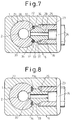
- the coupling 6 of the safety valve 5 has almost the same construction as that of the coupling 8 of the pressure sensor 7. Accordingly, only the coupling 8 of the safety valve 7 will be now described, with reference to Figs. 1, 6 and 7.
- the coupling 6 comprises a coupling member 22 and a nut 23, and a connecting pipe 25 is inserted between the main pipe 1 and the nut 23 to introduce fuel in the high pressure fuel passage 2 into the fuel passage 24 formed in the safety valve 5.
- a portion of the outer circumferential wall of the main pipe 1, on which the coupling member 22 is mounted is expanded outward, and this expanded portion 26 has the same diameter over the entire length thereof.
- the coupling member 22 has a bore 28 having an inner diameter almost the same as the outer diameter of the projection 27, and the bore 28 of the coupling member 22 is rotatably fitted onto the projection 27.
- a threaded bore 29 extending toward the bore 28 is formed in the coupling member 22, and the nut 23 is screwed into the threaded bore 29.
- a conical shape groove 30 connected to the high pressure fuel passage 2 and conically diverging toward the threaded bore 29 is formed on the outer circumferential wall of the expanded portion 26 of the main pipe 1, and the surrounding portion of the open end of the conical shape groove 30 is formed into an annular flat face 31.
- the tip face 32 of the connecting pipe 25 has a conical shape, and this conically shaped tip face 32 is seated on the conical shape groove 30.
- a flange 33 is integrally formed on the outer circumferential wall of the connecting pipe 25 at a position slightly inward from the conical shape tip face 32.
- a seal member 34 is inserted between the flange 33 and the flat face 31, and a V-shaped groove 35 (Fig. 7) is formed on the flat face 31 to retain the seal member 34 at a regular position.
- the inner end face 36 of the flange 33 has a conical shape
- the inner end face 37 of the nut 23 also has a conical shape.
- the conical shape inner and face 37 of the nut 23 is seated on the conical shape inner end face 36 of the flange 33.
- the tightening force is transmitted to the flange 33, whereby the conical shape tip face 32 of the connecting pipe 33 is pressed against the conical shaped groove 30.
- the coupling member 22 can not only rotate about the axis of the main pipe 1 but also can be tilted in all directions relative to a plane perpendicular to the axis of the main pipe 1.
- the tip portion of the connecting pipe 25 is inclined with respect to the axis of the conical shape groove 30 due to an error during the production of the conical shaped groove 30 or the conical shaped tip face 32 of the connecting pipe 25
- the tip portion of the connecting pipe 25 is fastened to the main pipe 1 by the nut 23 in a state such that the connecting pipe 25 is inclined, i.e., the coupling member 22 is inclined. Accordingly, there is no danger of a generation of an excessive stress in the coupling member 22 or the connecting pipe 25.
- Figure 8 illustrates an alternative embodiment of the coupling 6.
- the surrounding portion of the open end of the conical shape groove 30 is formed into an annular face 31a having a V-shaped cross-section, and a seal member 34 is inserted between the annular face 31a and the flange 33.
- a coupling for connecting a connecting pipe to a main pipe comprises a coupling member and a nut screwed into the coupling member.
- a projection having an arc-shaped cross-section and extending in the circumferential direction of the outer wall of the main pipe is formed on the outer wall of the main pipe, and the coupling member is rotatably fitted onto the projection.
- a conical shape groove connected to the high pressure fluid passage in the main pipe is formed on the outer wall of the main pipe, and the tip portion of the connecting pipe is pressed against the conical shape groove by tightening down the nut.
Landscapes
- Engineering & Computer Science (AREA)
- General Engineering & Computer Science (AREA)
- Mechanical Engineering (AREA)
- Chemical & Material Sciences (AREA)
- Combustion & Propulsion (AREA)
- Fuel-Injection Apparatus (AREA)
- Joints With Pressure Members (AREA)
- Branch Pipes, Bends, And The Like (AREA)
Applications Claiming Priority (2)
| Application Number | Priority Date | Filing Date | Title |
|---|---|---|---|
| JP75149/91 | 1991-04-08 | ||
| JP3075149A JP2803383B2 (ja) | 1991-04-08 | 1991-04-08 | 高圧流体用継手 |
Publications (3)
| Publication Number | Publication Date |
|---|---|
| EP0508362A2 true EP0508362A2 (de) | 1992-10-14 |
| EP0508362A3 EP0508362A3 (en) | 1993-07-07 |
| EP0508362B1 EP0508362B1 (de) | 1995-12-27 |
Family
ID=13567856
Family Applications (1)
| Application Number | Title | Priority Date | Filing Date |
|---|---|---|---|
| EP92105972A Expired - Lifetime EP0508362B1 (de) | 1991-04-08 | 1992-04-07 | Verbindung für Hochdruckleitungen |
Country Status (4)
| Country | Link |
|---|---|
| US (1) | US5261705A (de) |
| EP (1) | EP0508362B1 (de) |
| JP (1) | JP2803383B2 (de) |
| DE (1) | DE69207042T2 (de) |
Cited By (17)
| Publication number | Priority date | Publication date | Assignee | Title |
|---|---|---|---|---|
| FR2760203A1 (fr) * | 1997-03-03 | 1998-09-04 | Usui Kokusai Sangyo Kk | Rampe d'alimentation pour moteur diesel et procede de fabrication d'une telle rampe |
| EP0889231A1 (de) * | 1997-07-02 | 1999-01-07 | Robert Bosch Gmbh | Kraftstoffeinspritzsystem |
| WO2001009506A1 (de) * | 1999-08-03 | 2001-02-08 | Robert Bosch Gmbh | Kraftstoffhochdruckspeicher |
| WO2001042643A1 (de) * | 1999-12-08 | 2001-06-14 | Robert Bosch Gmbh | Anschlussstutzen und gehäuse für ein kraftstoffeinspritzsystem |
| GB2358898A (en) * | 1999-12-09 | 2001-08-08 | Usui Kokusai Sangyo Kk | Diesel engine fuel injection pipe with orifice pipe |
| WO2002055868A1 (de) * | 2001-01-12 | 2002-07-18 | Robert Bosch Gmbh | Common-rail einheit |
| WO2003040547A1 (de) * | 2001-11-07 | 2003-05-15 | Siemens Aktiengesellschaft | Verfahren zum herstellen einer kraftstoffspeicherleitung mit einem vorgespannten anschlussstück |
| EP1076172A3 (de) * | 1999-08-07 | 2003-10-01 | Winkelmann & Pannhoff GmbH | Vorrichtung zur Verteilung von Kraftstoff für Kraftstoffeinspritzanlagen von Verbrennungsmotoren |
| EP1079100A3 (de) * | 1999-08-27 | 2003-11-26 | Delphi Technologies, Inc. | Verbindungsanordnung |
| WO2003098030A1 (de) * | 2002-05-15 | 2003-11-27 | Siemens Aktiengesellschaft | Verbindungsanordnung mit integrierter drossel |
| WO2004004889A1 (de) * | 2002-07-03 | 2004-01-15 | Robert Bosch Gmbh | Dosiereinrichtung |
| EP1262656A3 (de) * | 2001-05-31 | 2004-08-25 | Siemens Aktiengesellschaft | Kraftstoffzuführvorrichtung |
| DE102011056118A1 (de) * | 2011-12-07 | 2013-06-13 | L'orange Gmbh | Modulares Common Rail-System für Brennkraftmaschinen |
| CN104169563A (zh) * | 2012-02-08 | 2014-11-26 | 罗伯特·博世有限公司 | 车辆中的燃料供给装置 |
| WO2019101519A1 (en) * | 2017-11-24 | 2019-05-31 | Robert Bosch Gmbh | A testing device for fuel injection valves |
| EP2665920B1 (de) * | 2011-01-21 | 2020-09-30 | Robert Bosch GmbH | Kraftstoffeinspritzventil mit verbessertem hochdruckanschluss |
| CN113404897A (zh) * | 2021-07-12 | 2021-09-17 | 西南石油大学 | 一种便于进行混油切割的混油输送用管道 |
Families Citing this family (27)
| Publication number | Priority date | Publication date | Assignee | Title |
|---|---|---|---|---|
| US5533765A (en) * | 1991-10-25 | 1996-07-09 | Nwd International, Inc. | Crimped tube-to-port hydraulic fittings |
| JPH09317599A (ja) | 1996-05-22 | 1997-12-09 | Usui Internatl Ind Co Ltd | コモンレールおよびその製造方法 |
| DE29619912U1 (de) * | 1996-11-18 | 1997-12-18 | Weh Gmbh, Verbindungstechnik, 89257 Illertissen | Anschlußadapter |
| JP3882964B2 (ja) * | 1996-11-30 | 2007-02-21 | 臼井国際産業株式会社 | コモンレールにおける分岐接続体の接続構造 |
| JPH10169873A (ja) * | 1996-12-07 | 1998-06-26 | Usui Internatl Ind Co Ltd | 高圧流体用分岐管継手 |
| JP2000234688A (ja) * | 1999-02-17 | 2000-08-29 | Usui Internatl Ind Co Ltd | コモンレールの製造方法 |
| DE19946611A1 (de) * | 1999-09-29 | 2001-04-12 | Bosch Gmbh Robert | Kraftstoffhochdruckspeicher |
| US6736431B2 (en) * | 2000-03-06 | 2004-05-18 | Robert Bosch Gmbh | High-pressure fuel accumulator |
| US6375232B1 (en) | 2000-04-27 | 2002-04-23 | The Boeing Company | Bi-metallic union fitting for use in threaded ports |
| US6637776B2 (en) | 2001-06-13 | 2003-10-28 | Cummins Inc. | Fluid manifold connector and fluid manifold assembly |
| JP4075838B2 (ja) * | 2003-06-27 | 2008-04-16 | 株式会社デンソー | 配管継手装置 |
| US7125051B2 (en) * | 2003-07-10 | 2006-10-24 | Usui Kokusai Sangyo Kaisha Limited | Common-rail injection system for diesel engine |
| US7591485B2 (en) * | 2005-07-11 | 2009-09-22 | Simmons Tom M | Connections for tubing and method of connecting tubing segments |
| SE530561C2 (sv) * | 2006-11-08 | 2008-07-08 | Scania Cv Ab | Anordning för att ansluta en högtrycksledning till en ackumulatortank |
| US8505515B2 (en) * | 2007-06-21 | 2013-08-13 | Volvo Lastvagnar Ab | Hydraulic connection of injector to a pressure source |
| US7543567B2 (en) * | 2007-10-29 | 2009-06-09 | Caterpillar Inc. | Fuel system having a one-piece hollow tube connection |
| US9157401B2 (en) * | 2008-01-14 | 2015-10-13 | Millennium Industries | Apparatus for coupling components of a fuel delivery system |
| US7516735B1 (en) * | 2008-01-16 | 2009-04-14 | Millennium Industries | Attachment for fuel injectors in a fuel delivery system |
| US8038178B2 (en) * | 2009-03-31 | 2011-10-18 | Hitachi, Ltd | High pressure fuel pipe construction for an internal combustion engine |
| US20130056979A1 (en) * | 2011-09-07 | 2013-03-07 | Basf Se | Holding device for sensors for high-pressure applications |
| DE202013103710U1 (de) * | 2013-08-15 | 2013-08-29 | Ti Automotive (Heidelberg) Gmbh | Kraftstoffverteilerleiste |
| CA2875512C (en) * | 2014-12-18 | 2015-12-08 | Westport Power Inc. | Sealing structure for gaseous fuel |
| DE102014226819A1 (de) * | 2014-12-22 | 2016-06-23 | Robert Bosch Gmbh | Einrichtung einer Brennstoffeinspritzanlage und metallische dichtende Verbindungsanordnung |
| GB201603445D0 (en) | 2016-02-29 | 2016-04-13 | Delphi Internat Operations Luxembourg S À R L | Fuel rail clamping arrangement |
| DE102017104608B4 (de) * | 2017-03-06 | 2022-12-29 | Gkn Powder Metallurgy Engineering Gmbh | Rohrleitungsabschnitt einer Common-Rail-Leitung und Verfahren zu dessen Herstellung |
| DE102019113471A1 (de) * | 2019-05-21 | 2020-11-26 | Dr. Ing. H.C. F. Porsche Aktiengesellschaft | Verbindungselement zum Verbinden zweier Fluidleitungen oder einer Fluidleitung mit einem Aggregat |
| JP7337725B2 (ja) * | 2020-02-14 | 2023-09-04 | 臼井国際産業株式会社 | 燃料圧力センサの接続構造 |
Family Cites Families (9)
| Publication number | Priority date | Publication date | Assignee | Title |
|---|---|---|---|---|
| US2147254A (en) * | 1935-07-15 | 1939-02-14 | Frank J Hinderliter | Rotary tool joint |
| DE6900393U (de) * | 1969-01-06 | 1969-06-12 | Altromin Gmbh Spezialfutter Gr | Verbindungsstueck fuer im winkel zueinander stehender kanaele |
| JPS4976114U (de) * | 1972-10-19 | 1974-07-02 | ||
| NL7902147A (nl) * | 1978-03-21 | 1979-09-25 | Tatra Np | Schroefverbinding voor het aansluiten van een perslei- ding, in het bijzonder van een inspuitleiding bij verbrandingsmotoren. |
| JPS63185988U (de) * | 1987-05-23 | 1988-11-29 | ||
| JPH0533832Y2 (de) * | 1987-06-29 | 1993-08-27 | ||
| JPH0533833Y2 (de) * | 1987-06-29 | 1993-08-27 | ||
| JP2898384B2 (ja) * | 1989-09-27 | 1999-05-31 | 臼井国際産業株式会社 | 高圧燃料レールにおける分岐接続体の接続構造 |
| US5172939A (en) * | 1989-10-14 | 1992-12-22 | Usui Kokusai Sangyo Kaisha Ltd. | Connection structure for branch pipe in high-pressure fuel rail |
-
1991
- 1991-04-08 JP JP3075149A patent/JP2803383B2/ja not_active Expired - Lifetime
-
1992
- 1992-03-26 US US07/858,116 patent/US5261705A/en not_active Expired - Fee Related
- 1992-04-07 DE DE69207042T patent/DE69207042T2/de not_active Expired - Fee Related
- 1992-04-07 EP EP92105972A patent/EP0508362B1/de not_active Expired - Lifetime
Cited By (23)
| Publication number | Priority date | Publication date | Assignee | Title |
|---|---|---|---|---|
| FR2760203A1 (fr) * | 1997-03-03 | 1998-09-04 | Usui Kokusai Sangyo Kk | Rampe d'alimentation pour moteur diesel et procede de fabrication d'une telle rampe |
| EP0889231A1 (de) * | 1997-07-02 | 1999-01-07 | Robert Bosch Gmbh | Kraftstoffeinspritzsystem |
| WO2001009506A1 (de) * | 1999-08-03 | 2001-02-08 | Robert Bosch Gmbh | Kraftstoffhochdruckspeicher |
| CZ296998B6 (cs) * | 1999-08-03 | 2006-08-16 | Robert Bosch Gmbh | Vysokotlaký zásobník paliva |
| EP1076172A3 (de) * | 1999-08-07 | 2003-10-01 | Winkelmann & Pannhoff GmbH | Vorrichtung zur Verteilung von Kraftstoff für Kraftstoffeinspritzanlagen von Verbrennungsmotoren |
| EP1079100A3 (de) * | 1999-08-27 | 2003-11-26 | Delphi Technologies, Inc. | Verbindungsanordnung |
| WO2001042643A1 (de) * | 1999-12-08 | 2001-06-14 | Robert Bosch Gmbh | Anschlussstutzen und gehäuse für ein kraftstoffeinspritzsystem |
| GB2358898B (en) * | 1999-12-09 | 2002-04-24 | Usui Kokusai Sangyo Kk | Diesel engine fuel injection pipe |
| GB2358898A (en) * | 1999-12-09 | 2001-08-08 | Usui Kokusai Sangyo Kk | Diesel engine fuel injection pipe with orifice pipe |
| WO2002055868A1 (de) * | 2001-01-12 | 2002-07-18 | Robert Bosch Gmbh | Common-rail einheit |
| EP1262656A3 (de) * | 2001-05-31 | 2004-08-25 | Siemens Aktiengesellschaft | Kraftstoffzuführvorrichtung |
| WO2003040547A1 (de) * | 2001-11-07 | 2003-05-15 | Siemens Aktiengesellschaft | Verfahren zum herstellen einer kraftstoffspeicherleitung mit einem vorgespannten anschlussstück |
| US7213577B2 (en) | 2001-11-07 | 2007-05-08 | Siemens Aktiengesellschaft | Method for producing a fuel accumulator line comprising a prestressed connection piece |
| WO2003098030A1 (de) * | 2002-05-15 | 2003-11-27 | Siemens Aktiengesellschaft | Verbindungsanordnung mit integrierter drossel |
| WO2004004889A1 (de) * | 2002-07-03 | 2004-01-15 | Robert Bosch Gmbh | Dosiereinrichtung |
| US7648084B2 (en) | 2002-07-03 | 2010-01-19 | Robert Bosch Gmbh | Dosing device |
| EP2665920B1 (de) * | 2011-01-21 | 2020-09-30 | Robert Bosch GmbH | Kraftstoffeinspritzventil mit verbessertem hochdruckanschluss |
| US10954906B2 (en) | 2011-01-21 | 2021-03-23 | Robert Bosch Gmbh | Fuel injector having an improved high-pressure connection |
| DE102011056118A1 (de) * | 2011-12-07 | 2013-06-13 | L'orange Gmbh | Modulares Common Rail-System für Brennkraftmaschinen |
| CN104169563A (zh) * | 2012-02-08 | 2014-11-26 | 罗伯特·博世有限公司 | 车辆中的燃料供给装置 |
| CN104169563B (zh) * | 2012-02-08 | 2019-07-16 | 罗伯特·博世有限公司 | 车辆中的燃料供给装置 |
| WO2019101519A1 (en) * | 2017-11-24 | 2019-05-31 | Robert Bosch Gmbh | A testing device for fuel injection valves |
| CN113404897A (zh) * | 2021-07-12 | 2021-09-17 | 西南石油大学 | 一种便于进行混油切割的混油输送用管道 |
Also Published As
| Publication number | Publication date |
|---|---|
| US5261705A (en) | 1993-11-16 |
| DE69207042D1 (de) | 1996-02-08 |
| JP2803383B2 (ja) | 1998-09-24 |
| EP0508362B1 (de) | 1995-12-27 |
| DE69207042T2 (de) | 1996-06-20 |
| EP0508362A3 (en) | 1993-07-07 |
| JPH04312286A (ja) | 1992-11-04 |
Similar Documents
| Publication | Publication Date | Title |
|---|---|---|
| EP0508362B1 (de) | Verbindung für Hochdruckleitungen | |
| US5120084A (en) | Connection structure for branching connector in high-pressure fuel rail | |
| US5169182A (en) | Branch connection in a high pressure fuel rail with gasket | |
| US5667255A (en) | Joint structure for joining a branch member to a high pressure fuel rail | |
| JP3109598B2 (ja) | 高圧燃料レールにおける分岐枝管の接続構造 | |
| US5961160A (en) | High-pressure connection system | |
| US6158781A (en) | Pipeline swivel coupling | |
| US5775302A (en) | Fuel distributor pipe | |
| US4252346A (en) | Connection for transition from a cutting ring joint or similar to a flange joint | |
| US5765534A (en) | Loading absorbing jumper tube assembly | |
| KR100691203B1 (ko) | 내연기관용 연료 분사 시스템을 위한 고압 연결부 | |
| US20060284421A1 (en) | High-pressure fuel line end fitting and method | |
| US7320486B2 (en) | Pipe clamp | |
| US20060163873A1 (en) | Connection assembly for pipelines | |
| US4953896A (en) | Structure for connecting branch pipe in high-pressure fuel manifold | |
| US5303964A (en) | Pipe connector | |
| US5052724A (en) | Threaded swivel connector | |
| JPH03177694A (ja) | 高圧燃料レールにおける分岐接続体の接続構造 | |
| JP2003532820A (ja) | 内燃機関用の燃料噴射系のための接続管片、及び予負荷されて溶接された接続管片を備えたケーシング、特に燃料高圧アキュムレータ | |
| US5332267A (en) | Tube coupling | |
| US4861077A (en) | Trapezoidal seal ring connection | |
| JPS62101989A (ja) | 管継手 | |
| US8025316B2 (en) | Device for connecting a high-pressure line to an accumulator tank | |
| US4618170A (en) | Coupled pipes and sealed unions therefor | |
| JPH10213045A (ja) | コモンレールにおける分岐接続体の接続構造 |
Legal Events
| Date | Code | Title | Description |
|---|---|---|---|
| PUAI | Public reference made under article 153(3) epc to a published international application that has entered the european phase |
Free format text: ORIGINAL CODE: 0009012 |
|
| 17P | Request for examination filed |
Effective date: 19920407 |
|
| AK | Designated contracting states |
Kind code of ref document: A2 Designated state(s): DE GB |
|
| PUAL | Search report despatched |
Free format text: ORIGINAL CODE: 0009013 |
|
| AK | Designated contracting states |
Kind code of ref document: A3 Designated state(s): DE GB |
|
| 17Q | First examination report despatched |
Effective date: 19941124 |
|
| GRAA | (expected) grant |
Free format text: ORIGINAL CODE: 0009210 |
|
| AK | Designated contracting states |
Kind code of ref document: B1 Designated state(s): DE GB |
|
| REF | Corresponds to: |
Ref document number: 69207042 Country of ref document: DE Date of ref document: 19960208 |
|
| PLBE | No opposition filed within time limit |
Free format text: ORIGINAL CODE: 0009261 |
|
| STAA | Information on the status of an ep patent application or granted ep patent |
Free format text: STATUS: NO OPPOSITION FILED WITHIN TIME LIMIT |
|
| 26N | No opposition filed | ||
| PGFP | Annual fee paid to national office [announced via postgrant information from national office to epo] |
Ref country code: DE Payment date: 20000403 Year of fee payment: 9 |
|
| PGFP | Annual fee paid to national office [announced via postgrant information from national office to epo] |
Ref country code: GB Payment date: 20000405 Year of fee payment: 9 |
|
| PG25 | Lapsed in a contracting state [announced via postgrant information from national office to epo] |
Ref country code: GB Free format text: LAPSE BECAUSE OF NON-PAYMENT OF DUE FEES Effective date: 20010407 |
|
| GBPC | Gb: european patent ceased through non-payment of renewal fee |
Effective date: 20010407 |
|
| PG25 | Lapsed in a contracting state [announced via postgrant information from national office to epo] |
Ref country code: DE Free format text: LAPSE BECAUSE OF NON-PAYMENT OF DUE FEES Effective date: 20020201 |