EP0509452A1 - Dispositif émetteur de lumière comportant une couche non-nucléation échelonnée - Google Patents
Dispositif émetteur de lumière comportant une couche non-nucléation échelonnée Download PDFInfo
- Publication number
- EP0509452A1 EP0509452A1 EP92106439A EP92106439A EP0509452A1 EP 0509452 A1 EP0509452 A1 EP 0509452A1 EP 92106439 A EP92106439 A EP 92106439A EP 92106439 A EP92106439 A EP 92106439A EP 0509452 A1 EP0509452 A1 EP 0509452A1
- Authority
- EP
- European Patent Office
- Prior art keywords
- light emitting
- emitting device
- layer portion
- nucleation layer
- nucleation
- Prior art date
- Legal status (The legal status is an assumption and is not a legal conclusion. Google has not performed a legal analysis and makes no representation as to the accuracy of the status listed.)
- Granted
Links
- 230000006911 nucleation Effects 0.000 title claims abstract description 89
- 238000010899 nucleation Methods 0.000 title claims abstract description 89
- 239000004065 semiconductor Substances 0.000 claims abstract description 55
- 150000001875 compounds Chemical class 0.000 claims abstract description 16
- 239000013078 crystal Substances 0.000 claims description 29
- 239000000463 material Substances 0.000 claims description 12
- 239000000758 substrate Substances 0.000 description 54
- VYPSYNLAJGMNEJ-UHFFFAOYSA-N silicon dioxide Inorganic materials O=[Si]=O VYPSYNLAJGMNEJ-UHFFFAOYSA-N 0.000 description 19
- 230000015572 biosynthetic process Effects 0.000 description 14
- 238000000034 method Methods 0.000 description 14
- 229910001218 Gallium arsenide Inorganic materials 0.000 description 12
- 235000012239 silicon dioxide Nutrition 0.000 description 11
- PNEYBMLMFCGWSK-UHFFFAOYSA-N aluminium oxide Inorganic materials [O-2].[O-2].[O-2].[Al+3].[Al+3] PNEYBMLMFCGWSK-UHFFFAOYSA-N 0.000 description 10
- 229910052593 corundum Inorganic materials 0.000 description 10
- 229910001845 yogo sapphire Inorganic materials 0.000 description 10
- 230000008020 evaporation Effects 0.000 description 9
- 238000001704 evaporation Methods 0.000 description 9
- 229910052681 coesite Inorganic materials 0.000 description 8
- 229910052906 cristobalite Inorganic materials 0.000 description 8
- 239000000377 silicon dioxide Substances 0.000 description 8
- 229910052682 stishovite Inorganic materials 0.000 description 8
- 229910052905 tridymite Inorganic materials 0.000 description 8
- 238000001312 dry etching Methods 0.000 description 6
- 238000010438 heat treatment Methods 0.000 description 6
- 238000005566 electron beam evaporation Methods 0.000 description 5
- 238000004519 manufacturing process Methods 0.000 description 5
- 238000005530 etching Methods 0.000 description 4
- XCZXGTMEAKBVPV-UHFFFAOYSA-N trimethylgallium Chemical compound C[Ga](C)C XCZXGTMEAKBVPV-UHFFFAOYSA-N 0.000 description 4
- YWWDBCBWQNCYNR-UHFFFAOYSA-N trimethylphosphine Chemical compound CP(C)C YWWDBCBWQNCYNR-UHFFFAOYSA-N 0.000 description 4
- 229910004205 SiNX Inorganic materials 0.000 description 3
- 238000003491 array Methods 0.000 description 3
- RBFQJDQYXXHULB-UHFFFAOYSA-N arsane Chemical compound [AsH3] RBFQJDQYXXHULB-UHFFFAOYSA-N 0.000 description 3
- 238000000151 deposition Methods 0.000 description 3
- 238000010586 diagram Methods 0.000 description 3
- 238000010884 ion-beam technique Methods 0.000 description 3
- 239000010453 quartz Substances 0.000 description 3
- 229910052782 aluminium Inorganic materials 0.000 description 2
- 229910052785 arsenic Inorganic materials 0.000 description 2
- 229910000070 arsenic hydride Inorganic materials 0.000 description 2
- 230000008021 deposition Effects 0.000 description 2
- 230000006866 deterioration Effects 0.000 description 2
- RVIXKDRPFPUUOO-UHFFFAOYSA-N dimethylselenide Chemical compound C[Se]C RVIXKDRPFPUUOO-UHFFFAOYSA-N 0.000 description 2
- 238000002474 experimental method Methods 0.000 description 2
- 229910052751 metal Inorganic materials 0.000 description 2
- 239000002184 metal Substances 0.000 description 2
- 238000012986 modification Methods 0.000 description 2
- 230000004048 modification Effects 0.000 description 2
- 230000001603 reducing effect Effects 0.000 description 2
- 238000004544 sputter deposition Methods 0.000 description 2
- PBCFLUZVCVVTBY-UHFFFAOYSA-N tantalum pentoxide Inorganic materials O=[Ta](=O)O[Ta](=O)=O PBCFLUZVCVVTBY-UHFFFAOYSA-N 0.000 description 2
- QTQRGDBFHFYIBH-UHFFFAOYSA-N tert-butylarsenic Chemical compound CC(C)(C)[As] QTQRGDBFHFYIBH-UHFFFAOYSA-N 0.000 description 2
- ZGNPLWZYVAFUNZ-UHFFFAOYSA-N tert-butylphosphane Chemical compound CC(C)(C)P ZGNPLWZYVAFUNZ-UHFFFAOYSA-N 0.000 description 2
- VOITXYVAKOUIBA-UHFFFAOYSA-N triethylaluminium Chemical compound CC[Al](CC)CC VOITXYVAKOUIBA-UHFFFAOYSA-N 0.000 description 2
- RGGPNXQUMRMPRA-UHFFFAOYSA-N triethylgallium Chemical compound CC[Ga](CC)CC RGGPNXQUMRMPRA-UHFFFAOYSA-N 0.000 description 2
- RXJKFRMDXUJTEX-UHFFFAOYSA-N triethylphosphine Chemical compound CCP(CC)CC RXJKFRMDXUJTEX-UHFFFAOYSA-N 0.000 description 2
- JLTRXTDYQLMHGR-UHFFFAOYSA-N trimethylaluminium Chemical compound C[Al](C)C JLTRXTDYQLMHGR-UHFFFAOYSA-N 0.000 description 2
- 238000001039 wet etching Methods 0.000 description 2
- BLRPTPMANUNPDV-UHFFFAOYSA-N Silane Chemical compound [SiH4] BLRPTPMANUNPDV-UHFFFAOYSA-N 0.000 description 1
- 208000034841 Thrombotic Microangiopathies Diseases 0.000 description 1
- QVGXLLKOCUKJST-UHFFFAOYSA-N atomic oxygen Chemical compound [O] QVGXLLKOCUKJST-UHFFFAOYSA-N 0.000 description 1
- 239000012159 carrier gas Substances 0.000 description 1
- 239000000919 ceramic Substances 0.000 description 1
- 238000005229 chemical vapour deposition Methods 0.000 description 1
- 238000010276 construction Methods 0.000 description 1
- NPPVFVGVCUPWGM-UHFFFAOYSA-N cyclopentane;magnesium Chemical compound [Mg].C1CCCC1 NPPVFVGVCUPWGM-UHFFFAOYSA-N 0.000 description 1
- JZCIYTSNUPIOMK-UHFFFAOYSA-N diethylarsenic Chemical compound CC[As]CC JZCIYTSNUPIOMK-UHFFFAOYSA-N 0.000 description 1
- HQWPLXHWEZZGKY-UHFFFAOYSA-N diethylzinc Chemical compound CC[Zn]CC HQWPLXHWEZZGKY-UHFFFAOYSA-N 0.000 description 1
- -1 dimethyl arsine Chemical compound 0.000 description 1
- YMUZFVVKDBZHGP-UHFFFAOYSA-N dimethyl telluride Chemical compound C[Te]C YMUZFVVKDBZHGP-UHFFFAOYSA-N 0.000 description 1
- 230000000694 effects Effects 0.000 description 1
- 238000010894 electron beam technology Methods 0.000 description 1
- ILXWFJOFKUNZJA-UHFFFAOYSA-N ethyltellanylethane Chemical compound CC[Te]CC ILXWFJOFKUNZJA-UHFFFAOYSA-N 0.000 description 1
- 230000001747 exhibiting effect Effects 0.000 description 1
- 239000007924 injection Substances 0.000 description 1
- 238000009434 installation Methods 0.000 description 1
- 150000002500 ions Chemical class 0.000 description 1
- NQITXDOXWXKYOI-UHFFFAOYSA-N magnesium;methylcyclopentane Chemical compound [Mg].CC1CCCC1 NQITXDOXWXKYOI-UHFFFAOYSA-N 0.000 description 1
- 230000003287 optical effect Effects 0.000 description 1
- 238000007254 oxidation reaction Methods 0.000 description 1
- 229910052760 oxygen Inorganic materials 0.000 description 1
- 239000001301 oxygen Substances 0.000 description 1
- 230000002093 peripheral effect Effects 0.000 description 1
- 229910000073 phosphorus hydride Inorganic materials 0.000 description 1
- 239000000243 solution Substances 0.000 description 1
- 235000013616 tea Nutrition 0.000 description 1
- 238000002154 thermal energy analyser detection Methods 0.000 description 1
- WWVNWQJKWKSDQM-UHFFFAOYSA-N triethylarsane Chemical compound CC[As](CC)CC WWVNWQJKWKSDQM-UHFFFAOYSA-N 0.000 description 1
- OTRPZROOJRIMKW-UHFFFAOYSA-N triethylindigane Chemical compound CC[In](CC)CC OTRPZROOJRIMKW-UHFFFAOYSA-N 0.000 description 1
- IBEFSUTVZWZJEL-UHFFFAOYSA-N trimethylindium Chemical compound C[In](C)C IBEFSUTVZWZJEL-UHFFFAOYSA-N 0.000 description 1
Images


Classifications
-
- H—ELECTRICITY
- H10—SEMICONDUCTOR DEVICES; ELECTRIC SOLID-STATE DEVICES NOT OTHERWISE PROVIDED FOR
- H10H—INORGANIC LIGHT-EMITTING SEMICONDUCTOR DEVICES HAVING POTENTIAL BARRIERS
- H10H20/00—Individual inorganic light-emitting semiconductor devices having potential barriers, e.g. light-emitting diodes [LED]
- H10H20/01—Manufacture or treatment
- H10H20/011—Manufacture or treatment of bodies, e.g. forming semiconductor layers
- H10H20/013—Manufacture or treatment of bodies, e.g. forming semiconductor layers having light-emitting regions comprising only Group III-V materials
- H10H20/0133—Manufacture or treatment of bodies, e.g. forming semiconductor layers having light-emitting regions comprising only Group III-V materials with a substrate not being Group III-V materials
Definitions
- the present invention relates to a light emitting device (LED) and, in particular, to an electrode wiring section of a light emitting device.
- LED light emitting device
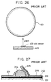
- a conventional LED array head for an electrophotographic printer is disclosed, for example, in Japanese Patent Laid-Open No.60-48384, according to which the LED array head comprises LED arrays prepared on compound-semiconductor-monocrystal substrates each having a length of approximately 1 to 2 cm, and these LED arrays are arranged on a support substrate and adhered thereto.
- Fig. 26 shows such a conventional LED array head comprising multiple LED arrays 403 which are arranged in a row on a support substrate 402 and adhered thereto. It is necessary to ensure a large space around the photosensitive drum 401 for the installation of the LED array head.
- the present inventors proposed a semiconductor device prepared by using a selective nucleation method.
- crystal growth is effected on a substrate having a free surface on which are arranged side by side the surface of an amorphous or polycrystalline non-nucleation layer having a small nucleation density, and parts of the surface of an amorphous or polycrystalline nucleation layer having a nucleation density larger than that of the non-nucleation layer, each of the parts of the latter surface having an area small enough for crystal growth to be effected starting from a single nucleus. Crystals are grown on this substrate, each starting from a single nucleus.
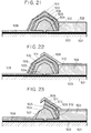
- Fig. 27 is a sectional view of a light emitting device prepared by the selective nucleation method.
- a nucleation layer 203 is formed by evaporation on a heat resistant substrate 201, and a non-nucleation layer 202 is deposited on the nucleation layer 203 by evaporation. The non-nucleation layer 202 is then partly removed to expose parts of the nucleation layer 203. Then, a p-type semiconductor region 204 is formed by crystal growth around each of the exposed parts of the nucleation layer 203. Further, an n-type semiconductor region 205 is formed on each p-type semiconductor region 204 by crystal growth. An electrode 207 is connected to each p-type semiconductor region 204, which is situated on the inner side, and an electrode 206 is connected to each n-type semiconductor region 205, which is situated on the outer side.
- a problem with the light emitting device formed by the conventional selective nucleation method, described above, is that there is a difference in level between the semiconductor crystal islands and the substrate surface on which the electrode wiring is provided for the electrodes outside the light emitting regions, with the result that the electrode wiring is liable to suffer disconnection.
- the invention in one aspect pertains to a light emitting device comprising a non-nucleation base layer including a first layer portion having an arbitrarily determined thickness as measured from a bottom surface of the first layer portion, a second layer portion having thickness greater than that of the first layer portion, and a wall surface connecting the first and second layer portions, thereby forming a step; a plurality of compound semiconductor crystal islands grown along the first layer portion and the wall surface, the growing starting either from a point on the first layer portion adjacent to the wall surface or on the wall surface; a plurality of light emitting regions formed on areas corresponding to concentric circles around the locations at which the compound semiconductor crystal islands are grown; electrodes disposed outside the light emitting regions, thereby forming electrode regions; and a wiring section formed on the second portion.
- the difference in level between the electrode regions outside the compound semiconductor crystal islands and the substrate surface on which the electrode wiring is provided is reduced, so that the electrode wiring is relatively resistant to disconnection.
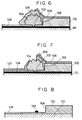
- Fig. 1 is a sectional view of a light emitting device according to the first embodiment of the present invention
- Figs. 2 to 7 are sectional views illustrating fabrication steps for the light emitting device shown in Fig. 1.
- This embodiment which has the fundamental structure of the light emitting device of the present invention, comprises: a heat resistant substrate 101; a non-nucleation layer 102, 108 comprising layer portions having different thicknesses; a wall surface 109 connecting the layer portions of the non-nucleation layer 102, 108 and thereby forming a step; a plurality of semiconductor crystal islands formed on the non-nucleation layer portion 108 so as to be arranged in the longitudinal dimension of the heat resistant substrate 101 (i.e., perpendicular to the plane of the drawing) at intervals of 50 ⁇ m; electrodes 106 and 107 formed on each of the semiconductor crystal islands; and wiring sections for these electrodes.
- the heat resistant substrate 101 comprises a semiconductor monocrystal substrate, such as an Si monocrystal substrate or a GaAs monocrystal substrate, an amorphous substrate, such as a quartz substrate or a ceramic substrate, a high-melting-point metal substrate, such as a W substrate or a Ti substrate, or the like. As shown in Fig.
- a nucleation layer 103 consisting of a non-monocrystalline material, such as Al2O3 or Ta2O5, which has a high nucleation density
- a non-nucleation layer 102 of a non-monocrystalline material such as SiO2 or SiN X
- electron beam evaporation, resistance heating evaporation, sputtering, or the like are deposited in that order on the heat resistant substrate 101 by electron beam evaporation, resistance heating evaporation, sputtering, or the like.
- a step is formed on the surface of the non-nucleation layer 102.
- the thickness d of the non-nucleation layer 102 and the height h of the step are determined such that d > h so that the nucleation layer 103 is not exposed on the surface of the non-nucleation layer 102 at this stage.
- minute parts of the layer portion 108, which comprises the lower layer portion of the non-nucleation layer 102, 108 are removed to partly expose the nucleation layer 103.
- the area of each of the parts of the nucleation layer 103 thus exposed is generally 10 ⁇ m square or less, more preferably 6 ⁇ m square or less, and most preferably, 3 ⁇ m square or less.
- the minimum distance between the center of each exposed area of the nucleation layer 103 and the boundary of the step is L
- R the distance between each of the exposed surfaces of the nucleation layer 103 and the top surface of the corresponding semiconductor crystal island, on which electrodes are formed
- a p-type semiconductor region 104 and an n-type semiconductor region 105 are successively formed by the metal organic chemical vapor deposition (MOCVD) method, using the exposed areas of the nucleation layer 103 as the starting points.
- MOCVD metal organic chemical vapor deposition
- Examples of the semiconductor material used include: TMG (trimethyl gallium), TEG (triethyl gallium), TMA (trimethyl aluminum), TEA (triethyl aluminum), TMIn (trimethyl indium), TEIn (triethyl indium), TBAs (tertiary butyl arsine), TMAs (trymethyl arsine), TEAs (triethyl arsine), DMAs (dimethyl arsine), DEAs (diethyl arsine), AsH3, TBP (tertiary butyl phosphine), TMP (trimethyl phosphine), TEP (triethyl phosphine), PH3, and NH3.
- TMG trimethyl gallium
- TEG triethyl gallium
- TMA trimethyl aluminum
- TEA triethyl aluminum
- TMIn trimethyl indium
- TEIn triethyl indium
- TBAs tertiary butyl arsine
- Examples of the doping material include: DMSe (dimethyl selenium), DMTe (dimethyl tellurium), DETe (diethyl tellurium), SiH4, DEZn (diethyl zinc), Cp2Mg (cyclopentane magnesium), and (MeCp)2MG (methyl cyclopentane magnesium).
- an electrode 106 is formed by resistance heating, electron beam heating or the like. Subsequently, as shown in Fig. 7, that portion of each n-type semiconductor region 105 which is not covered with the electrode 106 is removed by dry etching or wet etching to expose a part of the p-type semiconductor region 104, on which another electrode 107 is formed.
- the nucleation layer 103, the non-nucleation layer 102, 108, and the step thereon there are other methods of forming the nucleation layer 103, the non-nucleation layer 102, 108, and the step thereon.
- the non-nucleation layer 102, 108 consisting of a non-mononcrystalline material such as SiO2 or SiNx which has a low nucleation density, on the heat resistant substrate 101 by thermal oxidization, evaporation, sputtering, or the like, and then forming the step thereon in such a manner that the heat resistant substrate 101 is not exposed.
- Fig. 8 it is possible, as shown in Fig.
- a substrate having a low nucleation density such as a quartz substrate, as the heat resistant substrate, and then forming the step directly thereon.
- the nucleation layer 103 it is necessary to form the nucleation layer 103 as a minute region on the lower portion 108 of the non-nucleation layer.
- a layer of a material having a high nucleation density such as Al2O3 or Ta2O5 is formed on the non-nucleation surfaces 102 and 108 of a non-monocrystalline material, such as SiO2 or SiNx, by electron beam evaporation, resistance heating evaporation, or the like.
- the layer thus formed is removed by reactive ion beam etching (RIBE), ion beam etching (IBE) or the like, generally leaving the nucleation layer 103 consisting of minute regions.
- RIBE reactive ion beam etching
- IBE ion beam etching
- FIB focus ion beam
- Fig. 10 is a sectional view of a second embodiment of the present invention, which uses a substrate of the type shown in Fig. 9.
- Figs. 11 to 16 are sectional views illustrating fabrication steps for the light emitting device shown in Fig. 10.
- the light emitting device of this embodiment comprises: a base consisting of an Si substrate 301 in which a heat resistant substrate and non-nucleation surfaces 302 and 308 which form a step defined by a wall surface 309, are formed as one piece, and a plurality of nucleation regions 303 made of Al2O3 each having a size of 3 ⁇ m x 3 ⁇ m; a plurality of compound semiconductor crystal islands each comprising an n-type semiconductor region 304 made of n-GaAs, a p-type semiconductor region 305 made of p-GaAs; Au electrodes 306 and 307 connected to each semiconductor crystal island; and wiring sections for these electrodes.
- the above-mentioned base is formed by dry etching the substrate 301 to a depth of 5 ⁇ m to leave a portion having a width of 200 ⁇ m in the longitudinal direction of the substrate (which is perpendicular to the plane of this sectional view) on the surface of the quartz substrate 301 to define the non-nucleation surfaces 302 and 308 (shown in Fig. 10).
- the substrate 301 is formed by dry etching the substrate 301 to a depth of 5 ⁇ m to leave a portion having a width of 200 ⁇ m in the longitudinal direction of the substrate (which is perpendicular to the plane of this sectional view) on the surface of the quartz substrate 301 to define the non-nucleation surfaces 302 and 308 (shown in Fig. 10).
- Al2O3 is deposited by electron beam evaporation on the non-nucleation surfaces 302 and 308 to a thickness of 0.1 ⁇ m to form a nucleation layer 303, and then the Al2O3 is partly removed by wet etching in such a manner that minute Al2O3 regions, each 3.5 ⁇ m square, remain on the non-nucleation surface 308, the minute regions being arranged in the longitudinal direction of the substrate 301 at intervals of 50 ⁇ m.
- one of the electrodes 306 is formed on the upper surface of each p-type semiconductor region 305 by depositing Cr(500A)/Au(5000A) by resistance heating evaporation. Then, as shown in Fig. 16, using the electrodes 306 as a mask, etching is performed to such an extent that the n-type GaAs of the n-type semiconductor regions 304 is partly exposed, and AuGe(2000A)/Au(5000A) is deposited on the exposed portions of the n-type GaAs by resistance evaporation, thereby forming the electrodes 307. Then, the electrode wiring sections for these electrodes are provided on the non-nucleation surfaces 302 and 308. In this embodiment, the variation in the resistance of the light emitting device which, in the prior art, is 30 to 300 ⁇ , can be reduced to 25 to 100 ⁇ .
- Fig. 17 is a sectional view of one of the semiconductor crystal islands in the third embodiment; and Figs. 18 to 23 are sectional views showing the fabrication steps thereof.
- This light emitting device comprises: a base consisting of a heat resistant substrate 501, a non-nucleation layer having two layer portions 502 and 508, forming a step defined by a wall surface 512, and a plurality of nucleation regions 503; a plurality of compound semiconductor crystal islands each comprising n-type semiconductor regions 504 and 505, a non-doped semiconductor region 509, and p-type semiconductor regions 510 and 511; electrodes 506 and 507 formed thereon; and wiring sections for these electrodes.
- the heat resistant substrate 501 is an Si substrate, on which is deposited by electron beam evaporation a nucleation layer 503 consisting of an AIN layer having a thickness of 0.1 ⁇ m, and a non-nucleation layer 502 consisting of an SiO2 layer having a thickness of 5 ⁇ m.
- the non-nucleation layer 502 is partly removed by dry etching to a depth of 4.5 ⁇ m in such a manner as to leave non-nucleation layer portions each having a width of 50 ⁇ m and arranged in the longitudinal direction of the substrate (which is perpendicular to the plane of this sectional view) at intervals of 300 ⁇ m, thereby defining separate non-nucleation layer portions 502 and 508.
- minute holes of 1.2 ⁇ m square are formed by dry etching in the non-nucleation layer portion 508, at positions each 10 ⁇ m away from the boundary wall 512 between the non-nucleation layer portions 502 and 508, so as to be arranged parallel with the longitudinal direction of the non-nucleation layer portions 502 at intervals of 50 ⁇ m, thereby partly exposing the nucleation layer 503.
- the above-mentioned base is prepared.
- Cr(500A)/Au(5000A) is deposited by resistance heating evaporation in such a manner as to cover both the surfaces of the outermost layers, i.e., the p-type semiconductor regions 511 and the surfaces of the non-nucleation layer portions 502, thereby forming electrodes 506. Afterwards, as shown in Fig.
- etching is performed to such an extent that the n-type GaAs monocrystal portions constituting the n-type semiconductor regions 504 are partly exposed, and AuGe(2000A)/Au(5000A) is deposited on the surfaces of the exposed portions of the n-type GaAs layers and the surface of the non-nucleation layer portions 508 to form the electrodes 507. In this way, the light emitting device of the third embodiment of the invention is formed.
- three substrates were prepared, each comprising a heat resistant Si substrate and an Al2O3 layer as a nucleation layer deposited thereon to a depth of 0.1 ⁇ m by electron beam evaporation and an SiO2 layer as a non-nucleation layer deposited on the Al2O3 layer to depths of 2.2 ⁇ m, 6.2 ⁇ m and 8.2 ⁇ m, respectively.
- the evaporation was conducted in a vacuum of 1 x 1E -6 Torr while supplying oxygen at a rate of 10 cc/min.
- each of the three substrates were stripe-like recesses extending in the longitudinal direction of the substrate and arranged at intervals of 1 ⁇ m.
- Nine types of recesses were prepared, the widths thereof ranging from 2 ⁇ m to 10 ⁇ m.
- the steps of these recesses were formed by removing the SiO2 layer perpendicularly to the substrate to the extent that the thickness of the portion left after the removal was 0.2 ⁇ m.
- the removal of the SiO2 was effected by dry etching, which was conducted while supplying CF4 and O2 at rates of 20 cc/min. and 2 cc/min., respectively, and under the conditions of a pressure of 1 Torr and a discharge of 100W.
- minute Al2O3 regions each 2 ⁇ m square, were formed on the central line of each of the recesses, at intervals of 50 ⁇ m.
- the formation of the minute Al2O3 regions was effected by performing dry etching for five minutes on the SiO2 layer.
- GaAs polycrystal growth was effected at a V/III ratio of 40 while supplying AsH3 constantly at a rate of 1.8 x 10 ⁇ 5 mol/min.
- the III-Group material used was TMG (trimethyl gallium).
- H2 was supplied as a carrier gas at a rate of 10 l/min.
- the substrate temperature was 670°C, the pressure was 20 Torr, and the growth time was 70 minutes.
- Au lines having a width of 10 ⁇ m (and a thickness of 5000A) were arranged perpendicularly to the recesses on the substrate in such a manner as to overlap the semiconductor crystal islands, thus forming electrode wiring.
- Fig. 24 shows the ratio of the Au lines exhibiting an average resistance value.
- a step is formed on the non-nucleation surface of a light emitting device array prepared by the selective nucleation method, and compound semiconductor crystal islands are grown along the wall surface of the step, and further, the wiring section for the outer electrodes is formed on the surface of the non-nucleation layer portion which is at a higher level, thereby reducing the resistance of the electrode wiring and making the electrode wiring relatively resistant to disconnection during production and use.
- a light emitting device includes a non-nucleation layer on which a step is formed to define a non-nucleation surface.
- Compound semiconductor islands each consisting of n-type and p-type semiconductor regions, are formed along a wall surface constituting the boundary of the step, and outer and inner electrodes are formed thereon, with the wiring section for the outer electrodes being formed on the surface of the non-nucleation layer which is at a level higher than the non-nucleation surface.
- the electrodes and the electrode wiring section are positioned substantially at the same level, thus attaining a reduction in resistance value and an increase in strength.
Landscapes
- Led Devices (AREA)
Applications Claiming Priority (2)
| Application Number | Priority Date | Filing Date | Title |
|---|---|---|---|
| JP10812491A JP2753153B2 (ja) | 1991-04-15 | 1991-04-15 | 発光素子 |
| JP108124/91 | 1991-04-15 |
Publications (2)
| Publication Number | Publication Date |
|---|---|
| EP0509452A1 true EP0509452A1 (fr) | 1992-10-21 |
| EP0509452B1 EP0509452B1 (fr) | 1996-07-10 |
Family
ID=14476543
Family Applications (1)
| Application Number | Title | Priority Date | Filing Date |
|---|---|---|---|
| EP92106439A Expired - Lifetime EP0509452B1 (fr) | 1991-04-15 | 1992-04-14 | Dispositif émetteur de lumière comportant une couche non-nucléation échelonnée |
Country Status (5)
| Country | Link |
|---|---|
| US (1) | US5250819A (fr) |
| EP (1) | EP0509452B1 (fr) |
| JP (1) | JP2753153B2 (fr) |
| AT (1) | ATE140343T1 (fr) |
| DE (1) | DE69212042T2 (fr) |
Families Citing this family (3)
| Publication number | Priority date | Publication date | Assignee | Title |
|---|---|---|---|---|
| JPH0531957A (ja) * | 1991-05-23 | 1993-02-09 | Canon Inc | 発光装置、これを用いた光書き込みプリンターヘツド並びに該光書き込みプリンターヘツドによる光プリンター装置 |
| US6489637B1 (en) * | 1999-06-09 | 2002-12-03 | Sanyo Electric Co., Ltd. | Hybrid integrated circuit device |
| JP4310076B2 (ja) * | 2001-05-31 | 2009-08-05 | キヤノン株式会社 | 結晶性薄膜の製造方法 |
Citations (3)
| Publication number | Priority date | Publication date | Assignee | Title |
|---|---|---|---|---|
| EP0241316A2 (fr) * | 1986-04-11 | 1987-10-14 | Canon Kabushiki Kaisha | Procédé pour former une couche déposée cristalline |
| EP0285358A2 (fr) * | 1987-03-27 | 1988-10-05 | Canon Kabushiki Kaisha | Procédé pour produire un composé semi-conducteur et dispositif semi-conducteur utilisant le composé semi-conducteur ainsi obtenu |
| EP0339793A1 (fr) * | 1988-03-27 | 1989-11-02 | Canon Kabushiki Kaisha | Procédé de préparation d'une couche cristalline sur un substrat |
Family Cites Families (10)
| Publication number | Priority date | Publication date | Assignee | Title |
|---|---|---|---|---|
| JPS5429239B2 (fr) * | 1974-12-04 | 1979-09-21 | ||
| JPS59168671A (ja) * | 1983-03-15 | 1984-09-22 | Nec Corp | 半導体装置の製造方法 |
| JPS608384A (ja) * | 1983-06-28 | 1985-01-17 | Isao Miyake | アルカリハライドの螢光を窒素により活性化する方法 |
| US4768070A (en) * | 1986-03-20 | 1988-08-30 | Hitachi, Ltd | Optoelectronics device |
| JPS63239920A (ja) * | 1987-03-27 | 1988-10-05 | Canon Inc | 半導体素子用基板の製造方法 |
| DE3727488C2 (de) * | 1987-08-18 | 1994-05-26 | Telefunken Microelectron | Optoelektronisches Bauelement |
| JPH02125765A (ja) * | 1988-11-04 | 1990-05-14 | Mitsubishi Electric Corp | Ledアレイ・ヘッド |
| JPH02201975A (ja) * | 1989-01-31 | 1990-08-10 | Canon Inc | 発光装置 |
| JPH036858A (ja) * | 1989-06-02 | 1991-01-14 | Mitsubishi Electric Corp | マスタスライス方式半導体集積回路装置 |
| JPH036856A (ja) * | 1989-06-05 | 1991-01-14 | Canon Inc | 絶縁ゲート型半導体装置及びその形成方法 |
-
1991
- 1991-04-15 JP JP10812491A patent/JP2753153B2/ja not_active Expired - Fee Related
-
1992
- 1992-04-10 US US07/866,480 patent/US5250819A/en not_active Expired - Fee Related
- 1992-04-14 AT AT92106439T patent/ATE140343T1/de not_active IP Right Cessation
- 1992-04-14 DE DE69212042T patent/DE69212042T2/de not_active Expired - Fee Related
- 1992-04-14 EP EP92106439A patent/EP0509452B1/fr not_active Expired - Lifetime
Patent Citations (3)
| Publication number | Priority date | Publication date | Assignee | Title |
|---|---|---|---|---|
| EP0241316A2 (fr) * | 1986-04-11 | 1987-10-14 | Canon Kabushiki Kaisha | Procédé pour former une couche déposée cristalline |
| EP0285358A2 (fr) * | 1987-03-27 | 1988-10-05 | Canon Kabushiki Kaisha | Procédé pour produire un composé semi-conducteur et dispositif semi-conducteur utilisant le composé semi-conducteur ainsi obtenu |
| EP0339793A1 (fr) * | 1988-03-27 | 1989-11-02 | Canon Kabushiki Kaisha | Procédé de préparation d'une couche cristalline sur un substrat |
Non-Patent Citations (3)
| Title |
|---|
| PATENT ABSTRACTS OF JAPAN vol. 13, no. 44 (E-710)31 January 1989 & JP-A-63 239 920 ( CANON INC ) 5 October 1988 * |
| PATENT ABSTRACTS OF JAPAN vol. 15, no. 114 (E-1047)19 March 1991 & JP-A-3 006 856 ( CANON INC ) 14 January 1991 * |
| PATENT ABSTRACTS OF JAPAN vol. 9, no. 19 (E-292)25 January 1985 & JP-A-59 168 671 ( NIPPON DENKI KK ) 22 September 1984 * |
Also Published As
| Publication number | Publication date |
|---|---|
| EP0509452B1 (fr) | 1996-07-10 |
| JP2753153B2 (ja) | 1998-05-18 |
| US5250819A (en) | 1993-10-05 |
| DE69212042T2 (de) | 1997-01-02 |
| JPH04316375A (ja) | 1992-11-06 |
| ATE140343T1 (de) | 1996-07-15 |
| DE69212042D1 (de) | 1996-08-14 |
Similar Documents
| Publication | Publication Date | Title |
|---|---|---|
| US6936851B2 (en) | Semiconductor light-emitting device and method for manufacturing the same | |
| US5739552A (en) | Semiconductor light emitting diode producing visible light | |
| WO2021081308A1 (fr) | Procédé de fabrication d'une cavité résonante et miroirs réflecteurs de bragg répartis destiné à un laser à cavité verticale et à émission par la surface sur une aile d'une région de surcroissance latérale épitaxiale | |
| US5659184A (en) | III-V compound semiconductor device with a polycrystalline structure with minimum grain size of 0.6 μm and printer and display device utilizing the same | |
| JP3977920B2 (ja) | 半導体装置の製造方法 | |
| US5369290A (en) | Light emission element using a polycrystalline semiconductor material of III-V group compound | |
| US5243200A (en) | Semiconductor device having a substrate recess forming semiconductor regions | |
| EP0509452A1 (fr) | Dispositif émetteur de lumière comportant une couche non-nucléation échelonnée | |
| JPH07307489A (ja) | 半導体発光素子及びその製造方法 | |
| CA1280197C (fr) | Lasers planar integres monolithiquement a longueurs d'ondes differentes et leurmethode de fabrication | |
| US5548131A (en) | Light-emitting device, optical recording head utilizing said device, and optical printer utilizing said optical recording head | |
| JPH02286358A (ja) | 発光装置 | |
| JPS60960B2 (ja) | 窒化ガリウム発光素子アレイの製造方法 | |
| JP2831665B2 (ja) | 半導体発光装置 | |
| EP0514889B1 (fr) | Dispositif émetteur de lumière, tête d'imprimante d'enregistrement optique utilisant un tel dispositif, et imprimante optique utilisant une telle tête d'imprimante | |
| JP2766088B2 (ja) | 発光素子製造方法 | |
| JP3439955B2 (ja) | 半導体発光素子及びその製造方法 | |
| JP2885846B2 (ja) | 半導体装置 | |
| JP4121539B2 (ja) | 半導体装置の製造方法 | |
| JP2001332796A (ja) | 半導体レーザ装置の製造用トレー及びそれを用いた半導体レーザ装置の製造方法 | |
| JP2949886B2 (ja) | 半導体ウェハー及びその製造方法 | |
| JP2935381B2 (ja) | 発光素子アレー | |
| JP2786457B2 (ja) | 半導体素子およびその製造方法 | |
| JPH05217904A (ja) | 半導体レーザーダイオードの素子分離方法 | |
| JPH06232044A (ja) | 半導体膜の製造方法 |
Legal Events
| Date | Code | Title | Description |
|---|---|---|---|
| PUAI | Public reference made under article 153(3) epc to a published international application that has entered the european phase |
Free format text: ORIGINAL CODE: 0009012 |
|
| AK | Designated contracting states |
Kind code of ref document: A1 Designated state(s): AT BE CH DE DK ES FR GB GR IT LI LU NL PT SE |
|
| 17P | Request for examination filed |
Effective date: 19930308 |
|
| 17Q | First examination report despatched |
Effective date: 19940720 |
|
| GRAA | (expected) grant |
Free format text: ORIGINAL CODE: 0009210 |
|
| AK | Designated contracting states |
Kind code of ref document: B1 Designated state(s): AT BE CH DE DK ES FR GB GR IT LI LU NL PT SE |
|
| PG25 | Lapsed in a contracting state [announced via postgrant information from national office to epo] |
Ref country code: IT Free format text: LAPSE BECAUSE OF FAILURE TO SUBMIT A TRANSLATION OF THE DESCRIPTION OR TO PAY THE FEE WITHIN THE PRE;WARNING: LAPSES OF ITALIAN PATENTS WITH EFFECTIVE DATE BEFORE 2007 MAY HAVE OCCURRED AT ANY TIME BEFORE 2007. THE CORRECT EFFECTIVE DATE MAY BE DIFFERENT FROM THE ONE RECORDED.SCRIBED TIME-LIMIT Effective date: 19960710 Ref country code: LI Effective date: 19960710 Ref country code: CH Effective date: 19960710 Ref country code: DK Effective date: 19960710 Ref country code: AT Effective date: 19960710 Ref country code: BE Effective date: 19960710 Ref country code: ES Free format text: THE PATENT HAS BEEN ANNULLED BY A DECISION OF A NATIONAL AUTHORITY Effective date: 19960710 Ref country code: GR Free format text: LAPSE BECAUSE OF FAILURE TO SUBMIT A TRANSLATION OF THE DESCRIPTION OR TO PAY THE FEE WITHIN THE PRESCRIBED TIME-LIMIT Effective date: 19960710 Ref country code: NL Free format text: LAPSE BECAUSE OF FAILURE TO SUBMIT A TRANSLATION OF THE DESCRIPTION OR TO PAY THE FEE WITHIN THE PRESCRIBED TIME-LIMIT Effective date: 19960710 |
|
| REF | Corresponds to: |
Ref document number: 140343 Country of ref document: AT Date of ref document: 19960715 Kind code of ref document: T |
|
| GRAH | Despatch of communication of intention to grant a patent |
Free format text: ORIGINAL CODE: EPIDOS IGRA |
|
| REF | Corresponds to: |
Ref document number: 69212042 Country of ref document: DE Date of ref document: 19960814 |
|
| ET | Fr: translation filed | ||
| PG25 | Lapsed in a contracting state [announced via postgrant information from national office to epo] |
Ref country code: PT Effective date: 19961010 Ref country code: SE Effective date: 19961010 |
|
| NLV1 | Nl: lapsed or annulled due to failure to fulfill the requirements of art. 29p and 29m of the patents act | ||
| REG | Reference to a national code |
Ref country code: CH Ref legal event code: PL |
|
| PG25 | Lapsed in a contracting state [announced via postgrant information from national office to epo] |
Ref country code: LU Free format text: LAPSE BECAUSE OF NON-PAYMENT OF DUE FEES Effective date: 19970430 |
|
| PLBE | No opposition filed within time limit |
Free format text: ORIGINAL CODE: 0009261 |
|
| STAA | Information on the status of an ep patent application or granted ep patent |
Free format text: STATUS: NO OPPOSITION FILED WITHIN TIME LIMIT |
|
| 26N | No opposition filed | ||
| REG | Reference to a national code |
Ref country code: GB Ref legal event code: IF02 |
|
| PGFP | Annual fee paid to national office [announced via postgrant information from national office to epo] |
Ref country code: FR Payment date: 20030408 Year of fee payment: 12 |
|
| PGFP | Annual fee paid to national office [announced via postgrant information from national office to epo] |
Ref country code: GB Payment date: 20030409 Year of fee payment: 12 |
|
| PGFP | Annual fee paid to national office [announced via postgrant information from national office to epo] |
Ref country code: DE Payment date: 20030424 Year of fee payment: 12 |
|
| PG25 | Lapsed in a contracting state [announced via postgrant information from national office to epo] |
Ref country code: GB Free format text: LAPSE BECAUSE OF NON-PAYMENT OF DUE FEES Effective date: 20040414 |
|
| PG25 | Lapsed in a contracting state [announced via postgrant information from national office to epo] |
Ref country code: DE Free format text: LAPSE BECAUSE OF NON-PAYMENT OF DUE FEES Effective date: 20041103 |
|
| GBPC | Gb: european patent ceased through non-payment of renewal fee |
Effective date: 20040414 |
|
| PG25 | Lapsed in a contracting state [announced via postgrant information from national office to epo] |
Ref country code: FR Free format text: LAPSE BECAUSE OF NON-PAYMENT OF DUE FEES Effective date: 20041231 |
|
| REG | Reference to a national code |
Ref country code: FR Ref legal event code: ST |