EP0512625A2 - Dispositif de balayage optique - Google Patents
Dispositif de balayage optique Download PDFInfo
- Publication number
- EP0512625A2 EP0512625A2 EP92201218A EP92201218A EP0512625A2 EP 0512625 A2 EP0512625 A2 EP 0512625A2 EP 92201218 A EP92201218 A EP 92201218A EP 92201218 A EP92201218 A EP 92201218A EP 0512625 A2 EP0512625 A2 EP 0512625A2
- Authority
- EP
- European Patent Office
- Prior art keywords
- signal
- tracking
- track
- beams
- detection systems
- Prior art date
- Legal status (The legal status is an assumption and is not a legal conclusion. Google has not performed a legal analysis and makes no representation as to the accuracy of the status listed.)
- Granted
Links
Images

Classifications
-
- G—PHYSICS
- G11—INFORMATION STORAGE
- G11B—INFORMATION STORAGE BASED ON RELATIVE MOVEMENT BETWEEN RECORD CARRIER AND TRANSDUCER
- G11B7/00—Recording or reproducing by optical means, e.g. recording using a thermal beam of optical radiation by modifying optical properties or the physical structure, reproducing using an optical beam at lower power by sensing optical properties; Record carriers therefor
- G11B7/08—Disposition or mounting of heads or light sources relatively to record carriers
- G11B7/09—Disposition or mounting of heads or light sources relatively to record carriers with provision for moving the light beam or focus plane for the purpose of maintaining alignment of the light beam relative to the record carrier during transducing operation, e.g. to compensate for surface irregularities of the latter or for track following
- G11B7/0943—Methods and circuits for performing mathematical operations on individual detector segment outputs
-
- G—PHYSICS
- G11—INFORMATION STORAGE
- G11B—INFORMATION STORAGE BASED ON RELATIVE MOVEMENT BETWEEN RECORD CARRIER AND TRANSDUCER
- G11B7/00—Recording or reproducing by optical means, e.g. recording using a thermal beam of optical radiation by modifying optical properties or the physical structure, reproducing using an optical beam at lower power by sensing optical properties; Record carriers therefor
- G11B7/08—Disposition or mounting of heads or light sources relatively to record carriers
- G11B7/085—Disposition or mounting of heads or light sources relatively to record carriers with provision for moving the light beam into, or out of, its operative position or across tracks, otherwise than during the transducing operation, e.g. for adjustment or preliminary positioning or track change or selection
- G11B7/08505—Methods for track change, selection or preliminary positioning by moving the head
- G11B7/08517—Methods for track change, selection or preliminary positioning by moving the head with tracking pull-in only
-
- G—PHYSICS
- G11—INFORMATION STORAGE
- G11B—INFORMATION STORAGE BASED ON RELATIVE MOVEMENT BETWEEN RECORD CARRIER AND TRANSDUCER
- G11B7/00—Recording or reproducing by optical means, e.g. recording using a thermal beam of optical radiation by modifying optical properties or the physical structure, reproducing using an optical beam at lower power by sensing optical properties; Record carriers therefor
- G11B7/08—Disposition or mounting of heads or light sources relatively to record carriers
- G11B7/09—Disposition or mounting of heads or light sources relatively to record carriers with provision for moving the light beam or focus plane for the purpose of maintaining alignment of the light beam relative to the record carrier during transducing operation, e.g. to compensate for surface irregularities of the latter or for track following
- G11B7/0901—Disposition or mounting of heads or light sources relatively to record carriers with provision for moving the light beam or focus plane for the purpose of maintaining alignment of the light beam relative to the record carrier during transducing operation, e.g. to compensate for surface irregularities of the latter or for track following for track following only
- G11B7/0903—Multi-beam tracking systems
-
- G—PHYSICS
- G11—INFORMATION STORAGE
- G11B—INFORMATION STORAGE BASED ON RELATIVE MOVEMENT BETWEEN RECORD CARRIER AND TRANSDUCER
- G11B7/00—Recording or reproducing by optical means, e.g. recording using a thermal beam of optical radiation by modifying optical properties or the physical structure, reproducing using an optical beam at lower power by sensing optical properties; Record carriers therefor
- G11B7/08—Disposition or mounting of heads or light sources relatively to record carriers
- G11B7/09—Disposition or mounting of heads or light sources relatively to record carriers with provision for moving the light beam or focus plane for the purpose of maintaining alignment of the light beam relative to the record carrier during transducing operation, e.g. to compensate for surface irregularities of the latter or for track following
- G11B7/094—Methods and circuits for servo offset compensation
Definitions
- the invention relates to a device for optically scanning an information plane having tracks, which device comprises an optical system for generating two tracking beams and one main beam, a lens system for focusing the three beams on the record carrier to two tracking spots located at both sides of a track to be scanned and to one main spot on said track, and at least three detection systems a, b and c for receiving radiation of respectively the two tracking beams and the main beam from the record carrier, each detection system being split into at least two detectors.
- This device can be used in apparatuses for writing and reading optical record carriers.
- a scanning device of this type is known from European Patent Application no. 0,201,603.
- a tracking servosystem keeps the main spot on the track to be scanned.
- This system is controlled by means of a tracking error signal which is derived from the signals of the split detectors.
- a coarse control and a fine control can be used in the tracking servosystem.
- the coarse control is realised by moving a slide incorporating the scanning head into the transversal direction, i.e. the radial direction with respect to the round record carrier.
- the fine control can be realised by displacing an objective lens within the scanning head in the transversal direction. Due to such a displacement of the objective lens the radiation spots formed by the beams in the plane of the detectors will shift with respect to the associated detectors so that an offset is created in the tracking error signal with which the tracking servosystem is controlled.
- European Patent Application no. 0,201,603 describes a combination of detector signals producing a tracking error signal which is independent of small transversal displacements of the lens.
- a tracking error signal which is independent of small transversal displacements of the lens.
- Such displacements occur, for example, at the start of a searching action when the speed of the scanning head is considerably increased so as to proceed to another track on the record carrier.
- the signals supplied by the detectors are often distorted seriously so that errors occur when counting the number of tracks passed during the searching action.
- the present invention has for its object to obviate this drawback and provides an optical scanning device in which the influence of the position of the objective lens or another adjustable element incorporated in the light path on the tracking error signal is decreased.
- This scanning device is characterized in that the device comprises an element for adjusting the transversal position of the main spot with respect to the track to be scanned, and an electronic circuit for processing output signals of the detectors to a position signal which represents the position of the element.
- the position signal can be derived in a simple manner from the detector signals which are generated by the shift of the radiation spots on the detectors. As a result, it is no longer necessary to mount a separate position sensor proximate to the adjustable element.
- This element may be, for example, the above-mentioned objective lens or a rotatable mirror.
- the position of the element can be corrected in known manner by means of the position signal so that the beams pass the objective lens as centrally as possible.
- the position signal may control, for example, the fine control so as to keep the objective lens at a nominal position in the scanning head, the lens being used on its optical axis.
- the position signal can control the coarse control so as to position the scanning head in such a way that the objective lens can approximately stay in its nominal position for focusing the beams on the track to be followed.
- a particularly advantageous embodiment of the device is characterized in that the electronic circuit is adapted to supply a position signal which is proportional to the sum of two difference signals of the detection systems a and b and a constant multiplied by a difference signal of detection system c.
- This novel and inventive combination of detector signals yields a position signal which has the important advantage that it is only slightly influenced by movements of the spots transversely to the track direction.
- a further embodiment of the device is characterized in that the constant is equal to 2T, in which T is the intensity ratio between a tracking beam and the main beam.
- T is the intensity ratio between a tracking beam and the main beam.
- the two tracking beams may not have the same intensity due to a non-symmetrical intensity distribution of the beam from the radiation source or due to an asymmetry in the optical components between the radiation source and the detectors.
- a further embodiment of the device which is adapted thereto is characterized in that the difference signal of one of the detection systems a and b is corrected for an intensity difference between the two tracking beams. By multiplying the difference signal of detection system a or b by the intensity ratio of the two tracking beams, a correct position signal can be generated.
- a preferred embodiment of the device is characterized in that the distance between the two tracking spots in a direction perpendicular to the track to be scanned is equal to half a track period. Now, the position signal supplied by the electronic circuit is no longer influenced by movements of the spots transversely to the track direction.
- a further embodiment of the device according to the invention is characterized by a further electronic circuit which is connected to the outputs of the detectors and supplies a normalizing signal proportional to the sum signals of the detection systems a and b and 2T times the sum signal of the detection system c, and a normalizing circuit which is connected to the outputs of the two electronic circuits for supplying a normalized position signal. Due to the normalization the position signal has become independent of the intensity of the radiation source. Changes in this intensity will no longer lead to a change of the amplification in the control loop for controlling the position of the element.
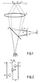
- Fig. 1 shows a part of an information plane 1 of a record carrier which is scanned by means of an optical head.
- the information plane has parallel tracks 2 or quasi-parallel tracks jointly forming a spiral track perpendicular to the plane of the drawing.
- the information may be stored as optically readable areas (not shown in the Figure) between or in the tracks.
- the optical head comprises a radiation source 3, for example, a diode laser whose radiation is incident on a grating 4.
- the grating splits the incoming beam into a +1, -1 and 0-order beam, i.e . a first tracking beam 5, a second tracking beam 6 and a main beam 7.
- a radiation source 3 for example, a diode laser whose radiation is incident on a grating 4.
- the grating splits the incoming beam into a +1, -1 and 0-order beam, i.e . a first tracking beam 5, a second tracking beam 6 and a main beam 7.
- a beam splitter 8 for example a partially transparent mirror, sends the beams towards an objective lens 9 which focuses the beams on the information plane 1.
- the positions of the spots formed on the information plane are shown in Fig. 2.
- the tracks 2 have a mutual distance q.
- Track 13 is the track to be followed by the scanning head.
- the first and second tracking beams form a tracking spot 14 and a tracking spot 15, respectively, both at a nominal distance x0 from the centre of track 13.
- the main spot 16 formed by the main beam is located on track 13.
- the radiation reflected by the information plane is passed towards three detection systems 10, 11, 12 via the objective lens 9 and the beam splitter 8.
- Detection system 10 receives radiation from the first tracking beam 5
- detection system 11 receives radiation from the second tracking beam 6
- detection system 12 receives radiation from the main beam.
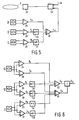
- Fig. 3 shows the three detection systems in a plan view.
- the detection systems 10, 11 and 12 are divided into two halves each by separating lines 17, 18 and 19, respectively, each half forming a detector. These detectors are denoted by the reference numerals 10a, 10b and 11a, 11b and 12a, 12b in the Figure.
- the separating lines extend parallel to the tracks 2 in the information plane 1.
- the spots formed by the three beams on the detectors are denoted by the reference numerals 21, 22 and 23 in Fig. 3.
- the information in the three beams is read in accordance with the push-pull method.
- the output signals of the detectors 10a and 10b are applied to a differential amplifier 24 for forming the push-pull signal Pa.
- differential amplifiers 25 and 26 form the push-pull signals Pb and Pc of detection systems 11 and 12, respectively.
- the three push-pull signals formed in this way may be beset with two different types of offset errors.
- the first offset error is produced when the three spots 21, 22 and 23 are offset with respect to the three detection systems 10, 11 and 12 in a direction perpendicular to the separating line 17.
- Such an offset occurs when the lens 9 is shifted sideward, i.e. transversely to the tracks, as is shown in Fig. 4.
- the solid lines show the lens 9 in the nominal position and the associated path of radiation of one of the beams 5, 6 or 7, and the broken lines show the lens 9 shifted over a distance x1 and the associated radiation path of the same beam.
- the position of the image 29 of the radiation source 3 remains unchanged.
- the main spot 16 on the information plane 1 moves sideways or transversally across the tracks 2 over a distance which is proportional to x1.
- a controlled shift of the lens 9 is therefore often used as a fine control for the transversal tracking of the main spot 16, while the coarse control consists of shifting the entire optical head in the transversal direction.
- the spot 23 is displaced across the detector plane by shifting the lens 9.
- the positions of the spots 21 and 22 are coupled to the position of the spot 23 so that in the case of a displacement of spot 23 with respect to the detection system 12 over a distance x d the spots 21 and 22 are displayed over the same distance with respect to their detection systems 10 and 11.
- the result is that the difference signals Pa, Pb and Pc each have an offset ⁇ s proportional to x d .
- a second offset error with which the three push-pull signals may be beset is the asymmetrical offset.
- This offset occurs when the distance between the separating lines 17 and 18 of the detection systems 10 and 11 is not equal to the distance between the centres of the spots 21 and 22 of the tracking beams. This causes the same offset ⁇ s , though opposite in sign, of the push-pull signals Pa and Pb.
- the asymmetrical offset is zero in the push-pull signal Pc.
- the asymmetrical offset may be caused by, for example, a temperature variation of the diode laser 3, which results in a variation of the wavelength of the emitted radiation. This changes the angle at which the grating 4 deflects the tracking beams 5 and 6 and hence the position of the spots 21 and 22 formed by the tracking beams on the detection systems 10 and 11.
- c is a detector-dependent constant which is determined by the efficiency of the conversion of radiation intensity into electric signal
- Ii is the intensity in beam i at the location of the detection system
- m is the modulation amplitude in the case of a transversal displacement of the scanning head across the tracks and dependent on the geometry of the tracks
- x is a tracking error or the transversal displacement of the spots 14, 15 and 16 when the main spot 16 does not exactly follow the track 13.
- the intensity Ii is principally determined by the intensity of the radiation from the laser 3, the intensity distribution across the beams realised by the grating 4 and the reflection of the information plane 1.
- Ia and Ib will be approximately equal. It is known from said European Patent Application no.
- the lens may be situated far away from the optical axis of the system. This may also occur at the start or the end of a searching action when the scanning head speed is increased considerably.
- a position signal is required which represents the position of the objective lens in the scanning head.
- the offset ⁇ s is determined in the device according to the invention, which offset is a measure of the displacement of the objective lens.
- the signal is free from modulation by the tracks 2 in the information plane, i.e. when the scanning head is displaced transversely across the tracks, the signal Ep does not vary due to the tracks.
- Ep can be used as a position error signal for a servosystem for correcting the position of the objective lens 9.
- the intensity in the two tracking beams 5 and 6 may be different. This may occur when, for example, the tracking beams are generated from the border rays of the beam from the laser 3, as described in Netherlands Patent Application no. 9002007 (PHN 13.445). If the intensity distribution in the beam is asymmetrical, the border rays will not be equally intensive and the tracking beams 5 and 6 will thus have a different intensity. Consequently, the signal Ep, given by formula (9) will still be dependent on x, i.e. the signal will exhibit modulation by the tracks. Then it is less well usable as a position signal for the objective lens.
- a satisfactory position signal can be obtained in this case by multiplying the push-pull signal Pb by a correction factor b, in which b is equal to the ratio between the intensity in spots 21 and 22 on the detection systems 10 and 11, respectively.
- Pa can of course also be multiplied by 1/b.
- the value of the position signal Ep in formula (9) is dependent on the intensity Ia incident on the detection system. This intensity depends, inter alia , on the quantity of radiation emitted by the laser 3 and on the reflection of the information plane 1. For example, if the laser supplies ten times more power during writing than during reading of information in the information plane, the position signal will also be ten times stronger during writing than during reading, independent of the position of the objective lens 9. This is an unwanted situation for a control loop. It is therefore desirable to make the position signal independent of the intensity on the detection systems. According to a further aspect of the invention, this can be realised by normalizing the position signal by means of a normalizing signal which is derived from the signals of the detection systems 10, 11 and 12.
- d is a constant which is approximately equal to 1
- n is a modulation amplitude which is dependent on the geometry of the tracks, comparable to the modulation amplitude m in the formulas (2), (3) and (4).
- the normalized position signal Ep' now is (17)
- the normalized position signal is now independent of the intensity of the laser 3, the reflection of the information plane 1 and the position of the scanning head with respect to the tracks 2.
- FIG. 5 An embodiment of an electronic circuit for generating a position signal of the objective lens 9 in accordance with formula (10) is shown in Fig. 5.
- the three push-pull signals Pa, Pb and Pc are derived in the same way from the signals of the detection systems 10, 11 and 12 as in Fig. 3.
- the signal Pc is multiplied by the constant factor 2T by means of a circuit 30 (see formula (7)). If the intensities in the spots 21 and 22 of the tracking beams 5 and 6 are not equal, the signal Pb must be multiplied by the constant b (see formula (11)) in a circuit 31.
- the circuits 30 and 31 may be integrated with the differential amplifiers 26 and 25, respectively.
- the output signals of the differential amplifier 24 and of the circuits 30 and 31 are added in a summing amplifier 32.
- the output signal of the summing amplifier is the position signal Ep.
- the position signal can be used as an input for a control circuit 33 which corrects the transversal position of the objective lens 9, i.e. in a direction perpendicular to the tracks as well as to the optical axis of the objective lens 9.
- the control circuit may have an additional input 34 for the tracking error signal Er.
- An actuator 35 displaces the objective lens in conformity with the output signal of the control circuit 33.
- the position signal Ep is used to keep the objective lens in its position.
- the signal Er is used to control the position of the objective lens as a fine control of the transversal tracking of the main spot 16.
- the signal Ep is then used for the coarse control which determines the position of the slide incorporating the scanning head with respect to the tracks. When the main spot 16 is held on a given track, the position of the objective lens in the scanning head can be corrected by controlling the position of the slide.
- FIG. 6 An electronic circuit for generating a position signal for the objective lens 9 normalized in accordance with formula (17) is shown in Fig. 6.
- the non-normalized position signal Ep is formed in the same way as in Fig. 5.
- a summing amplifier 36 produces the sum signal Sa which is proportional to the total intensity incident on the detection system 10.
- summing amplifiers 37 and 39 produce the sum signals Sb and Sc. If the intensities incident on the detection systems 10 and 11 are not equal, Sb must be multiplied by the constant b (see formula (11)) in a circuit 38.
- the sum signal Sc is multiplied by the constant factor 2T (see formula (7)) by means of a circuit 40.
- a summing amplifier 41 subsequently adds the outputs of the summing amplifier 36 and the two circuits 38 and 40.
- the output of the summing amplifier 41 is the normalizing signal Sn.
- a divider circuit 42 divides the position signal Ep by the normalizing signal Sn so as to obtain the normalized position signal Ep'.
- the last-mentioned signal may be applied to a control circuit 33 for positioning the objective lens 9.
- the detection system 12 may be divided into four quadrants for use with a main beam which is made astigmatic for generating a focus error signal as described in United States Patent no. 4,023,033. There are other methods of generating the focus error signal, which methods require a different division of the detection system 12. All methods can be used in the device according to the invention as long as a push-pull signal analogous to Pc can be derived from the detection system 12. In the embodiment described the fine control of the transversal position of the main spot is effected by displacing the objective lens, and the position signal is used for determining the position of this lens. The transversal position of the main spot can also be controlled by means of other elements. An example is the mirror 8 in Fig. 1.
- the main spot 16 can also be displaced by tilting this mirror.
- the position signal is now a measure of the tilt of the mirror with which a control circuit for the mirror can be controlled.
- the described electronic circuit for generating the position signal is only one out of many possible circuits performing the same function.
Landscapes
- Physics & Mathematics (AREA)
- Mathematical Physics (AREA)
- Optical Recording Or Reproduction (AREA)
- Microscoopes, Condenser (AREA)
- Holo Graphy (AREA)
- Analysing Materials By The Use Of Radiation (AREA)
- Moving Of The Head For Recording And Reproducing By Optical Means (AREA)
Applications Claiming Priority (2)
| Application Number | Priority Date | Filing Date | Title |
|---|---|---|---|
| EP91201139 | 1991-05-10 | ||
| EP91201139 | 1991-05-10 |
Publications (3)
| Publication Number | Publication Date |
|---|---|
| EP0512625A2 true EP0512625A2 (fr) | 1992-11-11 |
| EP0512625A3 EP0512625A3 (fr) | 1992-12-02 |
| EP0512625B1 EP0512625B1 (fr) | 1997-09-03 |
Family
ID=8207652
Family Applications (1)
| Application Number | Title | Priority Date | Filing Date |
|---|---|---|---|
| EP92201218A Expired - Lifetime EP0512625B1 (fr) | 1991-05-10 | 1992-05-04 | Dispositif de balayage optique |
Country Status (7)
| Country | Link |
|---|---|
| US (1) | US5173598A (fr) |
| EP (1) | EP0512625B1 (fr) |
| JP (1) | JP3720851B2 (fr) |
| CN (1) | CN1032276C (fr) |
| AT (1) | ATE157796T1 (fr) |
| DE (1) | DE69221931T2 (fr) |
| TW (1) | TW226046B (fr) |
Cited By (4)
| Publication number | Priority date | Publication date | Assignee | Title |
|---|---|---|---|---|
| EP0827138A3 (fr) * | 1996-08-27 | 1998-05-06 | Mitsumi Electric Co., Ltd. | Procédé de génération d'un signal oscillant dans un lecteur de disque du type CD-R |
| WO2002049022A1 (fr) * | 2000-12-13 | 2002-06-20 | Thomson Licensing S.A. | Procede de comptage de pistes et appareil correspondant permettant de lire et/ou d'ecrire dans un support d'enregistrement optique |
| WO2002049023A3 (fr) * | 2000-12-13 | 2003-01-09 | Thomson Licensing Sa | Procede servant a produire un signal de position de lentille et dispositif correspondant servant a lire et/ou a inscrire un support d'enregistrement optique |
| WO2007000682A1 (fr) * | 2005-06-27 | 2007-01-04 | Arima Devices Corporation | Unite de capteur optique utilisee dans un dispositif de lecture optique |
Families Citing this family (10)
| Publication number | Priority date | Publication date | Assignee | Title |
|---|---|---|---|---|
| TW444201B (en) * | 1998-02-16 | 2001-07-01 | Hitachi Ltd | Optical head |
| EP1163670B1 (fr) * | 1999-12-24 | 2008-08-20 | Koninklijke Philips Electronics N.V. | Tete de balayage optique |
| EP1169702A1 (fr) * | 1999-12-24 | 2002-01-09 | Koninklijke Philips Electronics N.V. | Modificateur de surface d'onde optique |
| DE10041569A1 (de) * | 2000-08-24 | 2002-03-07 | Thomson Brandt Gmbh | Verfahren zum Erzeugen eines korrigierten Fehlersignals sowie entsprechendes Gerät |
| JP2002319151A (ja) | 2001-04-24 | 2002-10-31 | Sharp Corp | 光ピックアップ装置 |
| AU2003281788A1 (en) * | 2002-07-30 | 2004-02-23 | Koninklijke Philips Electronics N.V. | Disc drive apparatus |
| US7140409B2 (en) * | 2004-11-01 | 2006-11-28 | Matthew Leberfinger | Portable pipe cutting apparatus |
| ATE460729T1 (de) | 2004-12-02 | 2010-03-15 | Koninkl Philips Electronics Nv | Verfahren und vorrichtung zur empfindlichkeitskompensation |
| EP1938320A2 (fr) * | 2005-09-19 | 2008-07-02 | Arima Devices Corporation | Lecteur optique presentant une correction d'aberration |
| CN104317049B (zh) * | 2014-10-15 | 2017-07-04 | 合肥工业大学 | 双偏心调整光路装置 |
Family Cites Families (10)
| Publication number | Priority date | Publication date | Assignee | Title |
|---|---|---|---|---|
| US4340950A (en) * | 1979-10-12 | 1982-07-20 | Universal Pioneer Corporation | Video disc player |
| US4462095A (en) * | 1982-03-19 | 1984-07-24 | Magnetic Peripherals Inc. | Moving diffraction grating for an information track centering system for optical recording |
| JPS6194246A (ja) * | 1984-10-15 | 1986-05-13 | Sony Corp | 光学式ヘッドのトラッキング誤差検出方法 |
| NL8500153A (nl) * | 1985-01-22 | 1986-08-18 | Philips Nv | Registratiedragerlichaam voorzien van een reliefstruktuur van optisch detekteerbare servospoorgedeelten en sektoradressen en inrichting voor het aanbrengen van deze struktuur. |
| US4750162A (en) * | 1985-07-16 | 1988-06-07 | Victor Company Of Japan, Ltd. | Optical tracking system utilizing three photo-detectors |
| DE3672426D1 (de) * | 1985-09-27 | 1990-08-09 | Sharp Kk | Spurnachlaufverfahren fuer eine optische speicherplatte. |
| JPS639034A (ja) * | 1986-06-30 | 1988-01-14 | Canon Inc | 光学的情報記録再生装置 |
| US5066138A (en) * | 1988-06-16 | 1991-11-19 | Mitsubishi Denki Kabushiki Kaisha | Optical head apparatus |
| JPH035927A (ja) * | 1989-06-01 | 1991-01-11 | Sony Corp | 光学記録および/または再生装置 |
| JPH0354733A (ja) * | 1989-07-21 | 1991-03-08 | Sony Corp | 光学記録および/または再生装置 |
-
1991
- 1991-07-22 US US07/733,926 patent/US5173598A/en not_active Expired - Lifetime
-
1992
- 1992-02-14 TW TW081101051A patent/TW226046B/zh active
- 1992-05-04 DE DE69221931T patent/DE69221931T2/de not_active Expired - Fee Related
- 1992-05-04 EP EP92201218A patent/EP0512625B1/fr not_active Expired - Lifetime
- 1992-05-04 AT AT92201218T patent/ATE157796T1/de not_active IP Right Cessation
- 1992-05-07 CN CN92103463A patent/CN1032276C/zh not_active Expired - Fee Related
- 1992-05-11 JP JP11754592A patent/JP3720851B2/ja not_active Expired - Fee Related
Cited By (7)
| Publication number | Priority date | Publication date | Assignee | Title |
|---|---|---|---|---|
| EP0827138A3 (fr) * | 1996-08-27 | 1998-05-06 | Mitsumi Electric Co., Ltd. | Procédé de génération d'un signal oscillant dans un lecteur de disque du type CD-R |
| US6009059A (en) * | 1996-08-27 | 1999-12-28 | Mitsumi Electric Co., Ltd. | Method for generating a wobble signal in a CD-R drive |
| WO2002049022A1 (fr) * | 2000-12-13 | 2002-06-20 | Thomson Licensing S.A. | Procede de comptage de pistes et appareil correspondant permettant de lire et/ou d'ecrire dans un support d'enregistrement optique |
| WO2002049023A3 (fr) * | 2000-12-13 | 2003-01-09 | Thomson Licensing Sa | Procede servant a produire un signal de position de lentille et dispositif correspondant servant a lire et/ou a inscrire un support d'enregistrement optique |
| US7266057B2 (en) | 2000-12-13 | 2007-09-04 | Thomson Licensing | Method for generating a lens position signal and corresponding apparatus for reading from and/or writing to an optical recording medium |
| US7345965B2 (en) | 2000-12-13 | 2008-03-18 | Thomson Licensing | Method for track counting and corresponding apparatus for reading from and/or writing to an optical recording medium |
| WO2007000682A1 (fr) * | 2005-06-27 | 2007-01-04 | Arima Devices Corporation | Unite de capteur optique utilisee dans un dispositif de lecture optique |
Also Published As
| Publication number | Publication date |
|---|---|
| ATE157796T1 (de) | 1997-09-15 |
| EP0512625B1 (fr) | 1997-09-03 |
| JPH05128548A (ja) | 1993-05-25 |
| DE69221931D1 (de) | 1997-10-09 |
| EP0512625A3 (fr) | 1992-12-02 |
| CN1032276C (zh) | 1996-07-10 |
| US5173598A (en) | 1992-12-22 |
| DE69221931T2 (de) | 1998-03-05 |
| CN1066733A (zh) | 1992-12-02 |
| TW226046B (fr) | 1994-07-01 |
| JP3720851B2 (ja) | 2005-11-30 |
Similar Documents
| Publication | Publication Date | Title |
|---|---|---|
| US4057833A (en) | Centering detection system for an apparatus for playing optically readable record carriers | |
| KR930005784B1 (ko) | 광학식 헤드의 트랙킹 오차 검출방식 | |
| US4742218A (en) | Focus error detection apparatus utilizing focusing an front and rear sides of focal planes | |
| US4006293A (en) | Apparatus for reading a flat record carrier with an optically readable information structure | |
| KR950010418B1 (ko) | 광기록재생장치 | |
| EP0512625B1 (fr) | Dispositif de balayage optique | |
| US4661944A (en) | Optical recording/playback apparatus having a focusing control system with reduced spot-offset sensitivity | |
| US4815060A (en) | Optical pickup device with tracking and focusing utilizing a photodetector having four regions | |
| US5404344A (en) | Recording/reproducing optical head producing focusing error signal from zero-th order diffracted light and tracking error signal from first order diffracted light | |
| EP0512616B1 (fr) | Dispositif de balayage optique | |
| JP4028599B2 (ja) | フォーカス制御のための閉ループサーボ動作 | |
| US5144131A (en) | Device for optically scanning an information plane detecting border portions of light beam | |
| US6512732B1 (en) | Device for optically scanning information tracks on a plane using two subbeams | |
| US7072268B2 (en) | Optical pickup apparatus, optical disk apparatus, and tracking error signal detection method | |
| US7248545B2 (en) | Optical pickup device | |
| JPH0612573B2 (ja) | 情報読取装置における記録トラックとピックアップとのトラック直交方向相対位置制御装置 | |
| JP2629456B2 (ja) | 対物レンズ位置検出装置 | |
| US5212674A (en) | Optical high density data reproducing apparatus using interference techniques | |
| JP3581941B2 (ja) | 光ディスク装置及び光ビームの投射位置調整方法 | |
| JPH11102526A (ja) | 光学ヘッドおよび光学的情報再生装置 | |
| JPH0554178B2 (fr) | ||
| KR20000005156A (ko) | 포커스 제어용 폐쇄 루프 서어보 동작 | |
| JPH05174407A (ja) | 光学式記録再生装置 | |
| JPH0528516A (ja) | 情報記録再生装置 | |
| JPH03260922A (ja) | 光学式ヘッド装置 |
Legal Events
| Date | Code | Title | Description |
|---|---|---|---|
| PUAI | Public reference made under article 153(3) epc to a published international application that has entered the european phase |
Free format text: ORIGINAL CODE: 0009012 |
|
| PUAL | Search report despatched |
Free format text: ORIGINAL CODE: 0009013 |
|
| AK | Designated contracting states |
Kind code of ref document: A2 Designated state(s): AT BE DE FR GB |
|
| AK | Designated contracting states |
Kind code of ref document: A3 Designated state(s): AT BE DE FR GB |
|
| 17P | Request for examination filed |
Effective date: 19930517 |
|
| 17Q | First examination report despatched |
Effective date: 19950714 |
|
| GRAG | Despatch of communication of intention to grant |
Free format text: ORIGINAL CODE: EPIDOS AGRA |
|
| GRAH | Despatch of communication of intention to grant a patent |
Free format text: ORIGINAL CODE: EPIDOS IGRA |
|
| GRAH | Despatch of communication of intention to grant a patent |
Free format text: ORIGINAL CODE: EPIDOS IGRA |
|
| GRAA | (expected) grant |
Free format text: ORIGINAL CODE: 0009210 |
|
| AK | Designated contracting states |
Kind code of ref document: B1 Designated state(s): AT BE DE FR GB |
|
| REF | Corresponds to: |
Ref document number: 157796 Country of ref document: AT Date of ref document: 19970915 Kind code of ref document: T |
|
| REF | Corresponds to: |
Ref document number: 69221931 Country of ref document: DE Date of ref document: 19971009 |
|
| ET | Fr: translation filed | ||
| PLBE | No opposition filed within time limit |
Free format text: ORIGINAL CODE: 0009261 |
|
| STAA | Information on the status of an ep patent application or granted ep patent |
Free format text: STATUS: NO OPPOSITION FILED WITHIN TIME LIMIT |
|
| 26N | No opposition filed | ||
| REG | Reference to a national code |
Ref country code: FR Ref legal event code: CD |
|
| REG | Reference to a national code |
Ref country code: GB Ref legal event code: IF02 |
|
| REG | Reference to a national code |
Ref country code: GB Ref legal event code: 746 Effective date: 20040811 |
|
| REG | Reference to a national code |
Ref country code: FR Ref legal event code: D6 |
|
| PGFP | Annual fee paid to national office [announced via postgrant information from national office to epo] |
Ref country code: DE Payment date: 20060714 Year of fee payment: 15 |
|
| PGFP | Annual fee paid to national office [announced via postgrant information from national office to epo] |
Ref country code: BE Payment date: 20070503 Year of fee payment: 16 |
|
| PGFP | Annual fee paid to national office [announced via postgrant information from national office to epo] |
Ref country code: AT Payment date: 20070524 Year of fee payment: 16 |
|
| PGFP | Annual fee paid to national office [announced via postgrant information from national office to epo] |
Ref country code: GB Payment date: 20070522 Year of fee payment: 16 |
|
| PG25 | Lapsed in a contracting state [announced via postgrant information from national office to epo] |
Ref country code: DE Free format text: LAPSE BECAUSE OF NON-PAYMENT OF DUE FEES Effective date: 20071201 |
|
| PGFP | Annual fee paid to national office [announced via postgrant information from national office to epo] |
Ref country code: FR Payment date: 20070529 Year of fee payment: 16 |
|
| BERE | Be: lapsed |
Owner name: *KONINKLIJKE PHILIPS ELECTRONICS N.V. Effective date: 20080531 |
|
| GBPC | Gb: european patent ceased through non-payment of renewal fee |
Effective date: 20080504 |
|
| PG25 | Lapsed in a contracting state [announced via postgrant information from national office to epo] |
Ref country code: AT Free format text: LAPSE BECAUSE OF NON-PAYMENT OF DUE FEES Effective date: 20080504 |
|
| REG | Reference to a national code |
Ref country code: FR Ref legal event code: ST Effective date: 20090119 |
|
| PG25 | Lapsed in a contracting state [announced via postgrant information from national office to epo] |
Ref country code: BE Free format text: LAPSE BECAUSE OF NON-PAYMENT OF DUE FEES Effective date: 20080531 |
|
| PG25 | Lapsed in a contracting state [announced via postgrant information from national office to epo] |
Ref country code: FR Free format text: LAPSE BECAUSE OF NON-PAYMENT OF DUE FEES Effective date: 20080602 |
|
| PG25 | Lapsed in a contracting state [announced via postgrant information from national office to epo] |
Ref country code: GB Free format text: LAPSE BECAUSE OF NON-PAYMENT OF DUE FEES Effective date: 20080504 |