EP0514364B1 - Vorrichtung zur Verwendung bei Inspektions- und Sanierungsarbeiten od.dgl. an Brückenuntersichten - Google Patents
Vorrichtung zur Verwendung bei Inspektions- und Sanierungsarbeiten od.dgl. an Brückenuntersichten Download PDFInfo
- Publication number
- EP0514364B1 EP0514364B1 EP19920890087 EP92890087A EP0514364B1 EP 0514364 B1 EP0514364 B1 EP 0514364B1 EP 19920890087 EP19920890087 EP 19920890087 EP 92890087 A EP92890087 A EP 92890087A EP 0514364 B1 EP0514364 B1 EP 0514364B1
- Authority
- EP
- European Patent Office
- Prior art keywords
- cables
- bridge
- cable
- working platform
- abutments
- Prior art date
- Legal status (The legal status is an assumption and is not a legal conclusion. Google has not performed a legal analysis and makes no representation as to the accuracy of the status listed.)
- Expired - Lifetime
Links
Images

Classifications
-
- E—FIXED CONSTRUCTIONS
- E01—CONSTRUCTION OF ROADS, RAILWAYS, OR BRIDGES
- E01D—CONSTRUCTION OF BRIDGES, ELEVATED ROADWAYS OR VIADUCTS; ASSEMBLY OF BRIDGES
- E01D19/00—Structural or constructional details of bridges
- E01D19/10—Railings; Protectors against smoke or gases, e.g. of locomotives; Maintenance travellers; Fastening of pipes or cables to bridges
- E01D19/106—Movable inspection or maintenance platforms, e.g. travelling scaffolding or vehicles specially designed to provide access to the undersides of bridges
Definitions
- the invention relates to a device for use in inspection and renovation work or the like on bridges with a cable car system with at least two ropes tensioned along the bridge and at least one work platform which can be moved by means of these ropes.
- the object of the invention is to provide a device for use in inspection and refurbishment work or the like on underside of the bridge, which is inexpensive and does not constitute a traffic obstruction.
- this object is achieved in a generic device in that for inspection and renovation work or the like the lower cableway system in the area of the lower bridge view, that the at least two cables of the cable car system are anchored to the bridge abutments, and that the work platform is at least one working platform suspended from the cables and extending transversely to the bridge. Since the working platform now hangs under the supporting structure, no structural structures are required to support the working platform on the carriageway, and the installation of a cable car system under the supporting structure is easy to carry out.
- the device is characterized in that the ropes are supporting ropes which are braced on the bridge abutments and which are supported by rope shoes which are attached to the supporting structure of the bridge.
- the suspension cables can be easily stretched between the bridge abutments and, depending on the length or the radius of the curve of the bridge, supported by any number of rope shoes to minimize the sag of the suspension cable to the required extent and the course of the suspension cable to the curvature to adapt the bridge in the curve area.
- the working platform can then have rope pulleys according to the invention, by means of which it can be moved on the supporting ropes.
- the ropes are carrying ropes that support the working platform and are connected to them, which are deflected at the bridge abutments and guided over support rollers, which, compared to the previously described embodiment, may possibly be different. can be more advantageous.
- base plates are fastened to the bridge abutments and to the structure of the bridge.
- the base plates on the bridge abutments have known rope anchorings and the base plates on the supporting structure have the rope shoes.
- the base plates with the cable anchorings or the cable shoes can be left after the work on the bridge, however can also be removed.
- the base plates can be left on the bridge abutments or on the supporting structure and the rope anchorings and the rope shoes can be removed.
- suspension cables or the ropes are guided past any supports. This offers the advantage that the transfer of the working platform from a field of the bridge into a further field which is separated from this field by a support can be carried out very simply in a manner which will be explained later.
- At least one traction rope is tensioned between the bridge abutments, by means of which the working platform can optionally be moved via a winch on the supporting cable.
- At least one, preferably two, cable winches are arranged on the working platform, by means of which the working platform can be moved vertically by means of holding ropes, by means of which the working platform is suspended from the supporting cables or the driving cables, then the distance between the working platform and the bottom view of the structure can be adjusted as required and it is also possible that the abutments and the support surfaces are accessible from one and the same working platform.
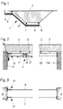
- a structure 2 of a bridge is shown in cross section.
- the structure 2 is a concrete structure in the present form, but the device according to the invention can also be used for structures in steel construction or other structures.
- three support cables 6, 7 and 8 are arranged on the bottom view of the supporting structure 2, which run approximately in the direction of the longitudinal extension of the bridge, and on which a working platform 1 is suspended.
- three support ropes 6, 7 and 8 are used, but the number of support ropes is essentially dependent on the width of the supporting structure or the shape of the work platform, which can be adapted to the shape of the bottom view.
- the work platform 1 consists of a horizontal lower part 9, an inclined part 10 and a part 11 projecting over the edge of the supporting structure 2, so that the inspection and the loading of equipment, tools and required material is possible directly from the road surface.
- the work platform may be inspected or loaded by means of an independently movable access scaffold part to the side of the supporting structure.
- the anchoring of the supporting cables 6, 7 and 8 takes place as in the embodiment of the device according to the invention shown in FIGS. 2 and 3 on the abutments 3 and 4 of the bridge, the anchoring being able to be carried out, for example, with the cable anchoring shown in FIG. 4.
- the supporting ropes 6 to 8 are shown by rope shoes 11, which are shown in FIGS. 5 and 6 are supported.
- the cable anchor 12 is detachably connected to a base plate 13, as shown in Fig. 4, which e.g. is screwed to the abutment 3 via dowels. After completion of the work, the base plate 13 can remain on the abutment 3 and be used again for new work.
- a tensioning device is fastened to the rope anchorage 12 and consists of a pulley 23, a tensioning rope 14 guided around a deflection roller 21 and a weight 15.
- the attachment of the suspension cable can be done using a conventional cable attachment, such as a wedge lock, attached to the rope anchor 12.
- rope shoes 11 are shown, by means of which the supporting rope is supported between the abutments 3 and 4, the rope shoe 11 shown in FIG. 5 being screwed directly to the supporting structure 2, whereas the rope shoe shown in FIG. 6 11 is fastened to the supporting structure 2 by means of a base plate 16 which is firmly connected to the supporting structure 2 and is left after the work on this has been completed.
- the work platform 1 is suspended via cable rollers 17, which are mounted on a roller holder 18, and holding cables 19 on the supporting cables 6 to 8, and can be moved (FIG. 6).
- a stationary cable 20 is tensioned parallel to the supporting cables 6, 7, 8, on which a gripping pull attached to the working platform 1 engages.
- a traction rope can be provided that is coupled to the work platform 1 (or can be coupled if required).
- Rope winches which are well known in the prior art and are not shown for this reason, are fastened to the work platform 1, by means of which the holding ropes 19 can be wound up and down.
- the work platform 1 can be raised and lowered vertically, so that the distance between the work platform and the bottom view can be adjusted as required, but also a vertical positioning of the work platform along the bridge abutment and any existing supports is possible.
- Another very important advantage of the device according to the invention is that the transfer of the work platform 1 from one work (bridge) field into another can be carried out very simply in the following way:
- the work platform 1 is lowered over the cable winches and the holding cables 19 along a support to the floor and then dismantled to such an extent that it can be moved to the other side of the support.
- the support rollers can then easily be moved to the correct position in the new structure field on the other side of the support on the support cables.
- the work platform is then reassembled in the new field and can be raised.
- suspension cables are arranged so that they are guided past the supports from abutments to abutments.
- a winch preferably operated by hand, can be used for this purpose, which winds up or unwinds one or, if necessary, two pulling ropes, which are anchored to the abutments or the supports.
- driving cables guided over deflection pulleys can also be used, in which case the holding cables 19 of the working platform 1 are clamped to the driving cables by suitable devices.
- the stage is moved by the movable ropes, which can be driven by a common or separate drive.
- the base plates 13 and 16 can also be attached to the structure by means of bolts which are guided through bores in the concrete parts, for example the webs and the base plate, and possibly screwed in with the interposition of tabs.
Landscapes
- Engineering & Computer Science (AREA)
- Architecture (AREA)
- Civil Engineering (AREA)
- Structural Engineering (AREA)
- Bridges Or Land Bridges (AREA)
Applications Claiming Priority (2)
| Application Number | Priority Date | Filing Date | Title |
|---|---|---|---|
| AT79891A AT402748B (de) | 1991-04-16 | 1991-04-16 | Vorrichtung zur verwendung bei inspektions- und sanierungsarbeiten od.dgl. an brückenuntersichten |
| AT798/91 | 1991-04-16 |
Publications (2)
| Publication Number | Publication Date |
|---|---|
| EP0514364A1 EP0514364A1 (de) | 1992-11-19 |
| EP0514364B1 true EP0514364B1 (de) | 1994-08-03 |
Family
ID=3499983
Family Applications (1)
| Application Number | Title | Priority Date | Filing Date |
|---|---|---|---|
| EP19920890087 Expired - Lifetime EP0514364B1 (de) | 1991-04-16 | 1992-04-09 | Vorrichtung zur Verwendung bei Inspektions- und Sanierungsarbeiten od.dgl. an Brückenuntersichten |
Country Status (8)
| Country | Link |
|---|---|
| EP (1) | EP0514364B1 (cs) |
| AT (1) | AT402748B (cs) |
| CZ (1) | CZ116992A3 (cs) |
| DE (1) | DE59200342D1 (cs) |
| DK (1) | DK0514364T3 (cs) |
| ES (1) | ES2063573T3 (cs) |
| HU (1) | HUT66050A (cs) |
| SK (1) | SK116992A3 (cs) |
Families Citing this family (7)
| Publication number | Priority date | Publication date | Assignee | Title |
|---|---|---|---|---|
| IT1314773B1 (it) * | 2000-01-20 | 2003-01-16 | Giancarlo Perazzini | Apparato per la manutenzione di viadotti |
| CN103255712B (zh) * | 2013-05-29 | 2015-04-08 | 株洲时代新材料科技股份有限公司 | 使用适用各种刚拱桥钢拱的检查维护装置的检查维护方法 |
| PL235194B1 (pl) * | 2015-08-10 | 2020-06-01 | Escort Spolka Z Ograniczona Odpowiedzialnoscia | Zestaw do mocowania urządzenia pomiarowego, zwłaszcza sonaru, do monitorowania ukształtowania dna wokół podpór mostowych, sposób mocowania urządzenia pomiarowego za pomocą takiego zestawu i zawiesie do mocowania urządzenia pomiarowego |
| CN105803936B (zh) * | 2015-09-10 | 2017-08-01 | 闫建磊 | 桥梁检测结构及其检测方法 |
| CN106436566A (zh) * | 2016-09-30 | 2017-02-22 | 济南城建集团有限公司 | 一种用于桥梁检测和加固的移动装置 |
| CN108221719B (zh) * | 2018-03-14 | 2023-09-19 | 北京市市政四建设工程有限责任公司 | 滑篮式桥梁检修系统及其安装方法 |
| CN109797649B (zh) * | 2019-01-31 | 2021-09-24 | 中铁桥隧技术有限公司 | 一种不影响桥面交通的检修车吊装方案 |
Family Cites Families (5)
| Publication number | Priority date | Publication date | Assignee | Title |
|---|---|---|---|---|
| US2067344A (en) * | 1936-06-13 | 1937-01-12 | William H Ringe | Bridge span inspection and maintenance traveler |
| DE1119317B (de) * | 1958-07-12 | 1961-12-14 | Stahlbau Albert Liesegang | Vorrichtung zum Durchfuehren von Unterhaltungsarbeiten an Tragkabeln und Haengeseilen von Haenge- und Zuegelgurtbruecken |
| DE1100068B (de) * | 1959-06-19 | 1961-02-23 | Maschf Augsburg Nuernberg Ag | Brueckenbesichtigungswagen fuer Deckbruecken mit veraenderlicher Haupttraegerhoehe und grosser Konsolenausladung |
| DE1230061B (de) * | 1960-12-23 | 1966-12-08 | Zarges Leichtmetallbau K G | Auf den Obergurten einer Bruecke verfahrbarer Untersuchungswagen |
| US4854419A (en) * | 1988-12-19 | 1989-08-08 | Lyras Louis G | Particulate containment control method and platform device |
-
1991
- 1991-04-16 AT AT79891A patent/AT402748B/de not_active IP Right Cessation
-
1992
- 1992-04-09 EP EP19920890087 patent/EP0514364B1/de not_active Expired - Lifetime
- 1992-04-09 DK DK92890087T patent/DK0514364T3/da not_active Application Discontinuation
- 1992-04-09 ES ES92890087T patent/ES2063573T3/es not_active Expired - Lifetime
- 1992-04-09 DE DE59200342T patent/DE59200342D1/de not_active Expired - Fee Related
- 1992-04-13 HU HU9201251A patent/HUT66050A/hu unknown
- 1992-04-16 SK SK116992A patent/SK116992A3/sk unknown
- 1992-04-16 CZ CS921169A patent/CZ116992A3/cs unknown
Also Published As
| Publication number | Publication date |
|---|---|
| ES2063573T3 (es) | 1995-01-01 |
| EP0514364A1 (de) | 1992-11-19 |
| SK116992A3 (en) | 1994-07-06 |
| HU9201251D0 (en) | 1992-07-28 |
| ATA79891A (de) | 1996-12-15 |
| HUT66050A (en) | 1994-09-28 |
| DE59200342D1 (de) | 1994-09-08 |
| CZ116992A3 (en) | 1993-03-17 |
| DK0514364T3 (da) | 1994-09-12 |
| AT402748B (de) | 1997-08-25 |
Similar Documents
| Publication | Publication Date | Title |
|---|---|---|
| EP3899167B1 (de) | Baustellenvorrichtung mit kletterschalung und aufzugssystem | |
| DE202021103010U1 (de) | Stützstruktur für Installation von zusammenfügbaren Abdeckbalken einer vorgefertigten Brücke | |
| EP0064183B1 (de) | Kletterschalung | |
| DE2400313C3 (de) | Hilfseinrichtung für Montage- und Wartungsarbeiten an einem Kühlturm | |
| DE3006491C2 (de) | Versetzbares, an einem Bauwerk verankertes Gerüst | |
| DE1900971A1 (de) | Bau-Aufzuganlage | |
| DE69413669T2 (de) | Gerüstvorrichtung | |
| DE19536994C2 (de) | Aufzugsystem und Verfahren zur Montage des Aufzugsystems | |
| EP2823860B1 (de) | Personensicherungssystem | |
| EP0514364B1 (de) | Vorrichtung zur Verwendung bei Inspektions- und Sanierungsarbeiten od.dgl. an Brückenuntersichten | |
| EP0350525B1 (de) | Verfahren zur Herstellung von Bauwerkswänden und Schalungssystem | |
| DE3526612A1 (de) | Brueckenseilinspektionsgeraet | |
| EP3381858A1 (de) | Bausatz für einen temporären lastenaufzug | |
| EP0356561A1 (de) | Handbaubare Grabenbrücke und Verfahren zur Aufstellung derselben | |
| DE2651566C2 (de) | Verfahren zum Montieren von Führungsschienen in Aufzugsschachtelementen sowie Einrichtungen zur Durchführung des Verfahrens | |
| DE19803954A1 (de) | Verfahren und Vorrichtung zum Erhöhen von Masten | |
| DE19922005A1 (de) | Gesimsbearbeitung | |
| DE29707488U1 (de) | Arbeitsgerüst zur Sanierung von Betonbrücken | |
| DE4430759C2 (de) | Verfahren und Vorrichtung zum Auswechseln eines Mastkopfes eines Winkeltragmastes einer Hochspannungsfreileitung | |
| DE102004009865B4 (de) | Vorrichtung für Brückensanierungsarbeiten | |
| DE2203044A1 (de) | Wagen zum verlegen von fertigteilfahrbahnplatten fuer brueckentragwerke | |
| DE2814141A1 (de) | Hubschalung fuer betonwaende, insbesondere brueckenpfeiler | |
| DE1658602B1 (de) | Vorrichtung zum Montieren der jeweils einen vollstaendigen Brueckenabschnitt umfassenden Fertigbauteile einer Spannbetonbruecke im abschnittsweisen Freivorbau | |
| DE4430760C2 (de) | Verfahren und Vorrichtung zum Auswechseln eines Mastkopfes eines Abspannmastes einer Hochspannungsfreileitung | |
| EP4644312A1 (de) | Montagebühne |
Legal Events
| Date | Code | Title | Description |
|---|---|---|---|
| PUAI | Public reference made under article 153(3) epc to a published international application that has entered the european phase |
Free format text: ORIGINAL CODE: 0009012 |
|
| AK | Designated contracting states |
Kind code of ref document: A1 Designated state(s): BE CH DE DK ES FR GB GR IT LI LU NL PT |
|
| 17P | Request for examination filed |
Effective date: 19930423 |
|
| 17Q | First examination report despatched |
Effective date: 19930621 |
|
| GRAA | (expected) grant |
Free format text: ORIGINAL CODE: 0009210 |
|
| AK | Designated contracting states |
Kind code of ref document: B1 Designated state(s): BE CH DE DK ES FR GB GR IT LI LU NL PT |
|
| REF | Corresponds to: |
Ref document number: 59200342 Country of ref document: DE Date of ref document: 19940908 |
|
| REG | Reference to a national code |
Ref country code: DK Ref legal event code: T3 |
|
| GBT | Gb: translation of ep patent filed (gb section 77(6)(a)/1977) |
Effective date: 19940815 |
|
| ET | Fr: translation filed | ||
| ITF | It: translation for a ep patent filed | ||
| REG | Reference to a national code |
Ref country code: ES Ref legal event code: FG2A Ref document number: 2063573 Country of ref document: ES Kind code of ref document: T3 |
|
| REG | Reference to a national code |
Ref country code: GR Ref legal event code: FG4A Free format text: 3013862 |
|
| SC4A | Pt: translation is available |
Free format text: 940804 AVAILABILITY OF NATIONAL TRANSLATION |
|
| PLBE | No opposition filed within time limit |
Free format text: ORIGINAL CODE: 0009261 |
|
| 26N | No opposition filed | ||
| PGFP | Annual fee paid to national office [announced via postgrant information from national office to epo] |
Ref country code: LU Payment date: 19960401 Year of fee payment: 5 |
|
| PGFP | Annual fee paid to national office [announced via postgrant information from national office to epo] |
Ref country code: PT Payment date: 19960404 Year of fee payment: 5 |
|
| PGFP | Annual fee paid to national office [announced via postgrant information from national office to epo] |
Ref country code: ES Payment date: 19960410 Year of fee payment: 5 |
|
| PGFP | Annual fee paid to national office [announced via postgrant information from national office to epo] |
Ref country code: GB Payment date: 19960411 Year of fee payment: 5 |
|
| PGFP | Annual fee paid to national office [announced via postgrant information from national office to epo] |
Ref country code: GR Payment date: 19960423 Year of fee payment: 5 |
|
| PGFP | Annual fee paid to national office [announced via postgrant information from national office to epo] |
Ref country code: DK Payment date: 19960425 Year of fee payment: 5 |
|
| PGFP | Annual fee paid to national office [announced via postgrant information from national office to epo] |
Ref country code: NL Payment date: 19960430 Year of fee payment: 5 |
|
| PGFP | Annual fee paid to national office [announced via postgrant information from national office to epo] |
Ref country code: BE Payment date: 19960507 Year of fee payment: 5 |
|
| PG25 | Lapsed in a contracting state [announced via postgrant information from national office to epo] |
Ref country code: LU Free format text: LAPSE BECAUSE OF NON-PAYMENT OF DUE FEES Effective date: 19970409 Ref country code: GB Effective date: 19970409 Ref country code: DK Effective date: 19970409 |
|
| REG | Reference to a national code |
Ref country code: DK Ref legal event code: EBP |
|
| PG25 | Lapsed in a contracting state [announced via postgrant information from national office to epo] |
Ref country code: ES Free format text: LAPSE BECAUSE OF NON-PAYMENT OF DUE FEES Effective date: 19970410 |
|
| PGFP | Annual fee paid to national office [announced via postgrant information from national office to epo] |
Ref country code: FR Payment date: 19970411 Year of fee payment: 6 |
|
| PG25 | Lapsed in a contracting state [announced via postgrant information from national office to epo] |
Ref country code: BE Effective date: 19970430 |
|
| PGFP | Annual fee paid to national office [announced via postgrant information from national office to epo] |
Ref country code: DE Payment date: 19970430 Year of fee payment: 6 |
|
| PGFP | Annual fee paid to national office [announced via postgrant information from national office to epo] |
Ref country code: CH Payment date: 19970521 Year of fee payment: 6 |
|
| BERE | Be: lapsed |
Owner name: H. JUNGER BAUGESELLSCHAFT M.B.H. UND CO. K.G. Effective date: 19970430 |
|
| PG25 | Lapsed in a contracting state [announced via postgrant information from national office to epo] |
Ref country code: PT Effective date: 19971031 Ref country code: GR Free format text: THE PATENT HAS BEEN ANNULLED BY A DECISION OF A NATIONAL AUTHORITY Effective date: 19971031 |
|
| PG25 | Lapsed in a contracting state [announced via postgrant information from national office to epo] |
Ref country code: NL Effective date: 19971101 |
|
| GBPC | Gb: european patent ceased through non-payment of renewal fee |
Effective date: 19970409 |
|
| REG | Reference to a national code |
Ref country code: GR Ref legal event code: MM2A Free format text: 3013862 |
|
| NLV4 | Nl: lapsed or anulled due to non-payment of the annual fee |
Effective date: 19971101 |
|
| REG | Reference to a national code |
Ref country code: PT Ref legal event code: MM4A Free format text: LAPSE DUE TO NON-PAYMENT OF FEES Effective date: 19971031 |
|
| PG25 | Lapsed in a contracting state [announced via postgrant information from national office to epo] |
Ref country code: LI Free format text: LAPSE BECAUSE OF NON-PAYMENT OF DUE FEES Effective date: 19980430 Ref country code: FR Free format text: THE PATENT HAS BEEN ANNULLED BY A DECISION OF A NATIONAL AUTHORITY Effective date: 19980430 Ref country code: CH Free format text: LAPSE BECAUSE OF NON-PAYMENT OF DUE FEES Effective date: 19980430 |
|
| REG | Reference to a national code |
Ref country code: CH Ref legal event code: PL |
|
| PG25 | Lapsed in a contracting state [announced via postgrant information from national office to epo] |
Ref country code: DE Free format text: LAPSE BECAUSE OF NON-PAYMENT OF DUE FEES Effective date: 19990202 |
|
| REG | Reference to a national code |
Ref country code: FR Ref legal event code: ST |
|
| REG | Reference to a national code |
Ref country code: ES Ref legal event code: FD2A Effective date: 19990201 |
|
| PG25 | Lapsed in a contracting state [announced via postgrant information from national office to epo] |
Ref country code: IT Free format text: LAPSE BECAUSE OF NON-PAYMENT OF DUE FEES;WARNING: LAPSES OF ITALIAN PATENTS WITH EFFECTIVE DATE BEFORE 2007 MAY HAVE OCCURRED AT ANY TIME BEFORE 2007. THE CORRECT EFFECTIVE DATE MAY BE DIFFERENT FROM THE ONE RECORDED. Effective date: 20050409 |