EP0519729A2 - Treiberschaltung eines Magnetkopfes - Google Patents
Treiberschaltung eines Magnetkopfes Download PDFInfo
- Publication number
- EP0519729A2 EP0519729A2 EP92305631A EP92305631A EP0519729A2 EP 0519729 A2 EP0519729 A2 EP 0519729A2 EP 92305631 A EP92305631 A EP 92305631A EP 92305631 A EP92305631 A EP 92305631A EP 0519729 A2 EP0519729 A2 EP 0519729A2
- Authority
- EP
- European Patent Office
- Prior art keywords
- magnetic head
- current
- coil
- driving circuit
- auxiliary
- Prior art date
- Legal status (The legal status is an assumption and is not a legal conclusion. Google has not performed a legal analysis and makes no representation as to the accuracy of the status listed.)
- Granted
Links
Images



Classifications
-
- G—PHYSICS
- G11—INFORMATION STORAGE
- G11B—INFORMATION STORAGE BASED ON RELATIVE MOVEMENT BETWEEN RECORD CARRIER AND TRANSDUCER
- G11B11/00—Recording on or reproducing from the same record carrier wherein for these two operations the methods are covered by different main groups of groups G11B3/00 - G11B7/00 or by different subgroups of group G11B9/00; Record carriers therefor
- G11B11/10—Recording on or reproducing from the same record carrier wherein for these two operations the methods are covered by different main groups of groups G11B3/00 - G11B7/00 or by different subgroups of group G11B9/00; Record carriers therefor using recording by magnetic means or other means for magnetisation or demagnetisation of a record carrier, e.g. light induced spin magnetisation; Demagnetisation by thermal or stress means in the presence or not of an orienting magnetic field
- G11B11/105—Recording on or reproducing from the same record carrier wherein for these two operations the methods are covered by different main groups of groups G11B3/00 - G11B7/00 or by different subgroups of group G11B9/00; Record carriers therefor using recording by magnetic means or other means for magnetisation or demagnetisation of a record carrier, e.g. light induced spin magnetisation; Demagnetisation by thermal or stress means in the presence or not of an orienting magnetic field using a beam of light or a magnetic field for recording by change of magnetisation and a beam of light for reproducing, i.e. magneto-optical, e.g. light-induced thermomagnetic recording, spin magnetisation recording, Kerr or Faraday effect reproducing
- G11B11/10502—Recording on or reproducing from the same record carrier wherein for these two operations the methods are covered by different main groups of groups G11B3/00 - G11B7/00 or by different subgroups of group G11B9/00; Record carriers therefor using recording by magnetic means or other means for magnetisation or demagnetisation of a record carrier, e.g. light induced spin magnetisation; Demagnetisation by thermal or stress means in the presence or not of an orienting magnetic field using a beam of light or a magnetic field for recording by change of magnetisation and a beam of light for reproducing, i.e. magneto-optical, e.g. light-induced thermomagnetic recording, spin magnetisation recording, Kerr or Faraday effect reproducing characterised by the transducing operation to be executed
- G11B11/1053—Recording on or reproducing from the same record carrier wherein for these two operations the methods are covered by different main groups of groups G11B3/00 - G11B7/00 or by different subgroups of group G11B9/00; Record carriers therefor using recording by magnetic means or other means for magnetisation or demagnetisation of a record carrier, e.g. light induced spin magnetisation; Demagnetisation by thermal or stress means in the presence or not of an orienting magnetic field using a beam of light or a magnetic field for recording by change of magnetisation and a beam of light for reproducing, i.e. magneto-optical, e.g. light-induced thermomagnetic recording, spin magnetisation recording, Kerr or Faraday effect reproducing characterised by the transducing operation to be executed to compensate for the magnetic domain drift or time shift
-
- G—PHYSICS
- G11—INFORMATION STORAGE
- G11B—INFORMATION STORAGE BASED ON RELATIVE MOVEMENT BETWEEN RECORD CARRIER AND TRANSDUCER
- G11B11/00—Recording on or reproducing from the same record carrier wherein for these two operations the methods are covered by different main groups of groups G11B3/00 - G11B7/00 or by different subgroups of group G11B9/00; Record carriers therefor
- G11B11/10—Recording on or reproducing from the same record carrier wherein for these two operations the methods are covered by different main groups of groups G11B3/00 - G11B7/00 or by different subgroups of group G11B9/00; Record carriers therefor using recording by magnetic means or other means for magnetisation or demagnetisation of a record carrier, e.g. light induced spin magnetisation; Demagnetisation by thermal or stress means in the presence or not of an orienting magnetic field
- G11B11/105—Recording on or reproducing from the same record carrier wherein for these two operations the methods are covered by different main groups of groups G11B3/00 - G11B7/00 or by different subgroups of group G11B9/00; Record carriers therefor using recording by magnetic means or other means for magnetisation or demagnetisation of a record carrier, e.g. light induced spin magnetisation; Demagnetisation by thermal or stress means in the presence or not of an orienting magnetic field using a beam of light or a magnetic field for recording by change of magnetisation and a beam of light for reproducing, i.e. magneto-optical, e.g. light-induced thermomagnetic recording, spin magnetisation recording, Kerr or Faraday effect reproducing
- G11B11/10502—Recording on or reproducing from the same record carrier wherein for these two operations the methods are covered by different main groups of groups G11B3/00 - G11B7/00 or by different subgroups of group G11B9/00; Record carriers therefor using recording by magnetic means or other means for magnetisation or demagnetisation of a record carrier, e.g. light induced spin magnetisation; Demagnetisation by thermal or stress means in the presence or not of an orienting magnetic field using a beam of light or a magnetic field for recording by change of magnetisation and a beam of light for reproducing, i.e. magneto-optical, e.g. light-induced thermomagnetic recording, spin magnetisation recording, Kerr or Faraday effect reproducing characterised by the transducing operation to be executed
- G11B11/10504—Recording
- G11B11/10508—Recording by modulating only the magnetic field at the transducer
Definitions
- the present invention relates to magnetic head driving circuits for driving a magnetic head for recording data on a recording medium, and more particularly, to a magnetic head driving circuit capable of over-writing data on a so-called magneto-optical disc.
- Fig. 4 is a block diagram explaining the principle of such magneto-optical disc apparatus.
- the magneto-optical disc apparatus shown in Fig. 4 comprises a magneto-optical disc 50 having a vertical magnetization film 51, a lens 52 for picking up a laser beam, a magnetic head 53 and a magnetic head driving circuit 54.
- the lens 52 narrows down a laser beam and directs the same to the vertical magnetization film 51 of the magneto-optical disc 50.
- the irradiation of the laser beam causes the temperature of the vertical magnetization film 51 to exceed a Curie point.
- the magnetic head driving circuit 54 generates a drive current I in response to input data and supplies the current I to the magnetic head 53.
- the magnetic head 53 generates a magnetic field H in response to the supplied current I.
- the generated magnetic field is applied to the portion whose temperature exceeds the Curie point.
- a magnetic pattern corresponding to the input data is recorded on the magneto-optical disc 50.
- a magnetic head circuit for resolving such problem is disclosed in Japanese Patent Laying-Open No. 63-94406.
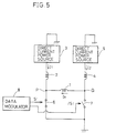
- Fig. 5 is a circuit diagram showing the magnetic head driving circuit described in Japanese Patent Laying-Open No. 63-94406.
- the magnetic head driving circuit comprises a magnetic head coil 1 having an impedance Lx, auxiliary coils 2 and 4, direct current power sources 3 and 5, switching devices 6 and 7, and a data modulator 8 for modulating input data (recording data) on a predetermined system to generate complementary recording signals S1, S1 ⁇ .
- the auxiliary coil 2 is connected between a node P which is one end of the magnetic head coil 1, and the direct current power source 3.
- the auxiliary coil 5 is connected between a node Q which is the other end of the magnetic head coil 1, and the direct current power source 5.
- Each of the auxiliary coils 2 and 4 has an impedance Ld (Ld >> Lx) larger than the impedance Lx of the magnetic head coil 1.
- the switching device 6 is connected between the node P and a ground terminal GND and is turned on/off in response to the recording signal S1.
- the switching device 7 is connected between the node Q and the ground terminal GND and is turned on/off in response to the recording signal S1 ⁇ .
- Fig. 6 is a diagram showing operation of the magnetic head driving circuit shown in Fig. 5.
- (a) is a waveform diagram of the recording signal S1
- (b) a waveform diagram of the recording signal S1 ⁇
- (c) a waveform diagram of the charging current I1 flowing through the auxiliary coil 2
- (d) a waveform diagram of the charging current I2 flowing through the auxiliary coil 4
- (e) a waveform diagram of the drive current Ix flowing through the magnetic head coil 1
- (f) shows a load impedance of the auxiliary coil 4
- (g) shows a load impedance of the auxiliary coil 2.
- the data modulator 8 modulates recording data to generate two recording signals S1 and S1 ⁇ complementary to each other.
- the recording signal S1 is applied to the switching device 6, while the recording signal S1 ⁇ is applied to the switching device 7.
- the switching device 6 is turned on in response to the recording signal S1 (logical high level) and the switching device 7 is turned off in response to the recording signal S1 ⁇ (logical low level)
- the circuit shown by the solid line in Fig. 5 is established wherein the charging current I1 for charging the auxiliary coil 2 flows from the direct current power source 3 to the ground terminal GND through the auxiliary coil 2 and the switching device 6.
- the charging current I2 for charging the auxiliary coil 4 flows from the direct current power source 5 to the ground terminal GND through the auxiliary coil 4, the magnetic head coil 1 and the switching device 6.
- the magnetic head coil 1 is supplied with the drive current I X from the node Q toward the node P.
- the charging current I2 for charging the auxiliary coil 4 flows from the direct current power source 5 to the ground terminal GND through the auxiliary coil 4 and the switching device 7.
- the charging current I1 for charging the auxiliary coil 2 flows from the direct current power source 3 to the ground terminal GND through the auxiliary coil 2, the magnetic head coil 1 and the switching device 7.
- the drive current I X therefore flows to the magnetic head coil 1 from the node P toward the node Q.
- the load of the auxiliary coil 2 (see Fig. 6 (g)) and the load of the auxiliary coil 4 (see Fig. 6 (f)) attain the impedance Lx of the magnetic head coil or 0.
- the above-mentioned impedance Ld should be as small as possible. As the impedance Ld is decreased, Ld becomes so large that it is not negligible with respect to Lx. In other words, load fluctuation occurs.
- the above-described problem becomes particularly conspicuous in the following case. That is, it is a case where a generally known and employed NRZI recording system (Non-return to Zero Inverse) of 2-7 RLL code (2-7 Run Length Limited) is used as modulation system for recording/reproduction in a magneto-optical disc apparatus. While such system has an advantage of increasing a recording density, it also has a disadvantage that a recording signal which recording bits are modulated includes a large amount of direct current components. It is therefore impossible to avoid the above-described problem when a recording signal of the above-described system is input to a conventional magnetic head driving circuit.
- NRZI recording system Non-return to Zero Inverse
- 2-7 RLL code 2-7 Run Length Limited
- Fig. 7 shows a bit arrangement of recording data based on the above-described 2-7 RLL code.
- the 2-7 RLL code includes two to seven "0" between “1” and “1". Modulation of the code by a data modulator of the NRZI system generates recording signals S1 and S1 ⁇ including a large amount of direct current components as shown in Figs. 6 (a) and (b).
- Fig. 8 is a circuit diagram of another magnetic head driving circuit disclosed in above-mentioned Japanese Patent Laying-Open No. 63-94406.
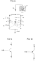
- the magnetic head driving circuit comprises a magnetic head coil 15, switching devices 11, 12, 13 and 14, a direct current power source 17 and an auxiliary coil 18.
- the relationship of the impedances between the auxiliary coil 18 and the magnetic head coil 15 is the same as that of the case shown in Fig. 5.
- the switching devices 11 and 14 both turn on/off in response to the recording signal S1.
- the switching devices 12 and 13 both turn on/off in response to the recording signal S1 ⁇ .
- the NPN transistor shown in Fig. 9 is used for the switching devices 11-14. Nodes C11 and E11 of Fig.
- NPN transistor 8 represent a collector and an emitter of the switching device 11 and nodes C13 and E13 represent a collector and an emitter of the switching device 13.
- the NPN transistor can be replaced by the PNP transistor shown in Figs. 10 or various devices such as FET (not shown).
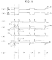
- Fig. 11 is a diagram illustrating the operation of the magnetic head driving circuit shown in Fig. 8.
- (a) and (b) show waveform diagrams of the signals S1 ⁇ and S1.
- (c), (d), (e) and (f) are waveform diagrams of the voltages of the collector C13, the emitter E13, the collector C11 and the emitter E11, respectively.
- (g) shows a load impedance of the auxiliary coil 18.
- the broken lines of (d) and (e) show base voltages of the switching devices 13 and 11.
- recording data is modulated to generate signals S1 and S1 ⁇ .
- the switching devices 12 and 13 turn on in response to the signal S1 ⁇ (high level), while the switching devices 11 and 14 turn off in response to the signal S1 (low level).
- the switching devices 12 and 13 turn off, while the switching devices 11 and 14 turn on.
- the charging current of the auxiliary coil 18 flows from the direct current power source 17 to the ground terminal GND through the auxiliary coil 18, the switching device 13, the magnetic head coil 15 and the switching device 12.
- the drive current I X is supplied to the magnetic head coil 15 from the node Q toward the node P .
- the charging current of the auxiliary coil 18 flows from the direct current power source 17 to the ground terminal GND through the auxiliary coil 18, the switching device 11, the magnetic head coil 15 and the switching device 14.
- the drive current I X is supplied to the magnetic head coil 15 from the node P toward the node Q.
- the load of the auxiliary coil 18 is fixed (equal to the impedance Lx of the magnetic head coil 15) as shown in Fig. 11 (g), in response to on/off of the switching devices 12 and 13 and the switching devices 14 and 11.
- the problem of load fluctuation in the magnetic head driving circuit of Fig. 5 is therefore resolved.
- the voltage waveforms of the collectors C13 and C11 and those of the emitters E13 and E11 have a large spike-shape because of the current flowing through the auxiliary coil 18 and the magnetic head coil 15 immediately after on or off of the switching devices 12 and 13 and the switching devices 14 and 11.
- the switching device 13 Since the voltage of the emitter E13 and the voltage of the emitter E11 become higher than the base voltages (indicated by X in Fig. 11) because of the spike-shaped waveform, the switching device 13 remains off (not shift to an on state) immediately after the base voltage is inverted from a low level to a high level, and conversely, the switching device 11 remains on (not shift to an off state) immediately after the base voltage is inverted from a high level to a low level (Y in Fig. 11).
- the drive current I X of the magnetic head is therefore slow to rise and fall. This is because of the circuit structure wherein the switching devices 13 and 11 are placed between the auxiliary coil 18 and the magnetic head 15.
- C13 and C11 are voltage waveforms of the emitters of the switching devices 13 and 11, respectively
- E13 and E11 are voltage waveforms of the collectors of the switching devices 13 and 11, respectively
- B13′ and B11′ are voltage waveforms of the bases of the switching devices 13 and 11, respectively.
- the voltage waveforms of the collectors E13 and E11 and those of the emitters C13 and C11 have a large spike-shape because of the current flowing through the auxiliary coil 18 and the magnetic head coil 15 immediately after on or off of the switching devices 12 and 13 and the switching devices 14 and 11.
- the switching device 11 Since the voltage of the emitter C13 (see Fig. 12 (c)) and the voltage of the emitter C11 (see Fig. 12 (e)) become higher than the base voltages because of the spike-shaped waveform, the switching device 11 remains on (not shift to an off state) immediately after the base voltage B13′ attains a high level (see Z in Fig. 12).
- the drive current Ix of the magnetic head is slow to rise and fall. This is also because of the circuit structure wherein the switching devices 13 and 11 are located between the auxiliary coil 18 and the magnetic head coil 15.
- the description is made of NPN or PNP transistor by way of example of the switching devices 12 and 13 and the switching devices 14 and 11, it is obvious that the same problem occurs even if a switching element of FET or the like is used.
- a magnetic head circuit having improved rise and fall characteristics of a drive current to be applied to a magnetic head coil is disclosed in Japanese Patent Laying-Open No. 63-24402.
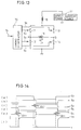
- Fig. 13 is a schematic circuit diagram of the magnetic head driving circuit disclosed in said Patent Laying-Open No. 63-24402.
- the magnetic head driving circuit shown in Fig. 13 differs from that of Fig. 8 in that a timing generator 19 is provided for generating signals S2, S3, S4 and S5 for-controlling on/off timing of the switching devices 11-14 in response to the recording signal S1.
- the signal S2 is applied to the switching device 12, the signal S3 to the switching device 11, the signal S4 to the switching device 14 and the signal S5 to the switching device 13.
- Fig. 14 is an output waveform diagram of each circuit of the magnetic head driving circuit shown in Fig. 13.
- (a) shows a waveform diagram of the recording signal S1
- (b) shows that of the signal S2
- (c) shows that of the signal S3
- (d) shows that of the signal S4
- (e) shows that of the signal S5
- (f) shows a waveform of the drive current I X .
- the switching device 11 and the switching device 14 changes from on to off in response to the change of the signal S3 from a high level to a low level and the change of the signal S4 from a high level to a low level, respectively.
- the switching device 13 is turned on in response to the signal S5 which has risen earlier by a predetermined time ⁇ T1 than the falls of said signals S3 and S4.
- the signal S3 is brought to high prior to falls of the signals S2 and S5.
- a time difference between the falls of the signals S2 and S5 and the rise of the signal S3 is represented as ⁇ T2.
- the switching device 11 therefore turns on before the switching devices 13 and 12 turn off.
- One object of the present invention is to record data at a high speed by providing the same amount of currents to a magnetic head coil in one direction and in the opposite direction in a magnetic head driving circuit.
- Another object of the present invention is to record data at a high speed in a magnetic head driving circuit while by reducing spike noise caused by a direction change of a drive current.
- a further object of the present invention is to record data at a high speed in a magnetic head driving circuit without delaying a recording signal.
- the magnetic head driving circuit includes a first auxiliary coil, a second auxiliary coil, a current generator and a path forming circuit.
- the first auxiliary coil has an impedance larger than that of the magnetic head coil and is connected to one end of the same.
- the second auxiliary coil has an impedance of the same value as that of the first auxiliary coil and is connected to the other end of the magnetic head coil.
- the current generator generates a first current for charging one of the first and the second auxiliary coils and for driving the magnetic head coil in response to input data, and a second current having a current value equivalent to the subtraction of a current amount for driving the magnetic head coil from the first current and for charging the other of the first and the second auxiliary coils.
- the path forming circuit forms a first path for supplying the first current generated by the current generator to the magnetic head coil through one of the first and the second auxiliary coils in response to input data, and a second path for supplying the second current to the other of the first and the second auxiliary coils.
- the first current flows to the magnetic head coil through one of the first and the second auxiliary coils.
- the second current flows only to the first and the second auxiliary coils. Since the current value of the second current is equivalent to the subtraction of a current for driving the magnetic head coil from the first current value, the current values of the respective auxiliary coils are equal to each other, so that load impedances of the respective auxiliary coils are substantially the same.
- the drive current can be normally inverted even immediately after the inversion of a recording signal. This allows the drive current to suddenly rise and fall. Furthermore, since the load of the auxiliary coil does not constantly attain 0, power consumption can be reduced.
- the magnetic head driving circuit includes a microcomputer.
- the microcomputer includes a first current generation portion, a second current generation portion, a data conversion portion and a current supply portion.
- the first current generation portion generates a first current.
- the second current generation portion generates a second current.
- the data modulation portion modulates input data to generate a recording signal.
- the current supply portion supplies the first current to one of the first and the second auxiliary coils in response to one state of the recording signal generated by the data modulation portion and supplies the second current to the other of the first and the second auxiliary coils in response to the other state of the recording signal.
- the microcomputer is equivalent to the current generator and similarly operates to that of the first described circuit according to the present invention.
- the microcomputer enables a magnetic head driving circuit to be made compact, which is a great advantage to the magnetic head driving circuit whose size should be small.
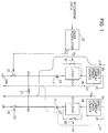
- Fig. 1 is a circuit diagram showing one embodiment of a magnetic head driving circuit according to the present invention.
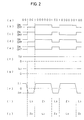
- Fig. 2 is a timing chart of a case where data of 2-7RLL code is applied to the magnetic head driving circuit shown in Fig. 1.
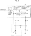
- Fig. 3 is a block diagram showing another embodiment of the magnetic head driving circuit according to the present invention.
- Fig. 4 is a block diagram illustrating the principle of a magneto-optical disc apparatus.
- Fig. 5 is a circuit diagram of a conventional magnetic head driving circuit.
- Fig. 6 is a timing chart showing operation of the magnetic head driving circuit shown in Fig. 5.
- Fig. 7 is a diagram showing a bit arrangement according to the 2-7 RLL code.
- Fig. 8 is a circuit diagram of another conventional magnetic head driving circuit.
- Fig. 9 is a circuit diagram showing one example of a switching device shown in Fig. 8.
- Fig. 10 is a circuit diagram showing another example of the switching device of Fig. 8.
- Fig. 11 is a timing chart showing operation of the magnetic head driving circuit shown in Fig. 8.
- Fig. 12 is a timing chart showing operation of the magnetic head driving circuit in a case where a PNP transistor is used as the switching device in Fig. 8.
- Fig. 13 is a circuit diagram of a conventional magnetic head driving circuit.
- Fig. 14 is an output waveform diagram of each circuit of the magnetic head driving circuit shown in Fig. 13.
- Fig. 1 is a circuit diagram showing one embodiment of a magnetic head driving circuit according to the present invention.
- the magnetic head driving circuit includes direct current power sources 24 and 25, dummy loads 28 and 29, switching devices 30 and 31, auxiliary coils 22 and 23, a magnetic head coil 2 l having an equivalent impedance L3, switching devices 26 and 27, and a data modulator 32.
- the data modulator 32 modulates data of a predetermined code, 2-7RLL code, for example, based on the NRZI modulation system to generate recording signals S1 and S1 ⁇ complementary to each other.
- the direct current power source 24 has a negative terminal (not shown) connected to a ground terminal GND and a positive terminal (not shown) connected to one end of the dummy load 28.
- the dummy load 28 has an impedance Z1 approximately equal to the impedance L3 of the magnetic head coil 21.
- the switching device 30 is connected in parallel with the dummy load 28.
- the other end of the dummy load 28 is connected to one end of the auxiliary coil 22 (equivalent impedance of which is L1), and the other end of the auxiliary coil 22 is connected to one end (node Q0) of the switching device 26.
- the other end of the switching device 26 is connected to the ground terminal GND.
- the direct current power source 25 has a negative terminal (not shown) connected to the ground terminal GND and a positive terminal (not shown) connected to one end of the dummy load 29.
- the dummy load 29 has an impedance Z2 approximately equal to the impedance of the magnetic head coil 21.
- the switching device 31 is connected in parallel with the dummy load 29.
- the other end of the dummy load 29 is connected to one end of the auxiliary coil 23 (equivalent impedance of which is L2), and the other end of the auxiliary coil 23 is connected to one end (node P0) of the switching device 27.
- the other end of the switching device 27 is connected to the ground terminal GND.
- the magnetic head coil 21 whose equivalent impedance is L3 is connected between the node Q0 between the auxiliary coil 22 and the switching device 26 and the node P0 between the auxiliary coil 23 and the switching device 27.
- the auxiliary coils 22 and 23 have impedances larger than the impedance of the magnetic head coil 21, and transmit a drive current to the magnetic head coil 21 and increase an inversion rate of the drive current.
- Both of the dummy loads 28 and 29 have the same impedances as that of the magnetic head coil 21.
- the switching devices 26 and 31 turn on/off in response to the recording signal S1, while the switching devices 27 and 30 turn on/off in response to the recording signal S1 ⁇ complementary to the recording signal S1.
- the switching devices 26, 27, 30 and 31 supply the drive current to the magnetic head coil 21 from one of the direct current power sources 24 and 25 in response to the recording signal.
- the switching devices 27 and 30 are off.
- the switching devices 27 and 30 are on, the switching devices 26 and 31 are off.
- the input recording data is modulated by the date modulator 32 and the recording signals S1 and S1 ⁇ are generated.
- the recording signal S1 is applied to the switching devices 27 and 31, while the recording signal S1 ⁇ is applied to the switching devices 26 and 31.
- the switching devices 26 and 31 and the switching devices 27 and 30 are controlled to be on or off as indicated by the solid line of Fig. 1.
- a current I11 flows from the node P0 toward the node Q0
- a current I12 flows to ground from the direct current power source 24 through the load 28, the auxiliary coil 22 and the switching device 26.
- the switching devices 26 and 31 and the switching devices 27 and 30 are controlled to be on or off as indicated by the dotted line of Fig. 1.
- a current I21 flows from the node Q0 toward the node P0
- a current I22 flows to ground from the direct current power source 25 through the load 29, the auxiliary coil 23 and the switching device 27.
- On/off of the switching devices 26, 27, 30 and 31 is controlled in response to the recording signals S1 and S1 ⁇ to switch (invert) the direction of the drive current to be applied to the magnetic head coil 21 in this way.
- the total amount of the load for each of the auxiliary coils 22 and 23 can be made constant by on/off controlling of the switches 26, 27, 30 and 31 in this way. Description will be given later of a fixed total of the load.
- Fig. 2 is a timing chart of a case where data of the 2-7RLL code is applied to the magnetic head driving circuit shown in Fig. 1.
- (a) shows a bit arrangement of the 2-7RLL code
- (b) and (d) show the states of the recording signal S1 ⁇ and the switching devices 26 and 31
- (c) and (e) show the states of the recording signal S1 and the switching devices 27 and 30,
- (f) shows a charging current IL2 flowing through the auxiliary coil 22
- (g) shows a charging current IL1 flowing through the auxiliary coil 23
- (h) shows a drive current flowing through the magnetic head coil 21
- (i) shows a load impedance of the auxiliary coil 22
- (j) shows a load impedance of the auxiliary coil 23.
- the switching devices 26 and 31 and the switching devices 27 and 30 are turned on/off as indicated by the solid line or the dotted line in Fig. 1 based on the recording bit of Fig. 2 (a).
- the dummy load 28 is the only load for the auxiliary coil 22.
- the load of the auxiliary coil 22 therefore totals to Z1.
- the magnetic head coil 21 is the only load for the auxiliary coil 22.
- the load of the auxiliary coil 22 therefore totals to L3.
- the load of the auxiliary coil 22 alternately totals to a value of the equivalent impedance Z1 or the equivalent impedance L3 in response to on/off of each switching device (see Fig. 2(i)).
- the magnetic head coil 21 is the only load for the auxiliary coil 23.
- the load of the auxiliary coil 23 therefore totals to L3.
- the dummy load 29 is the only load for the auxiliary coil 23.
- the load of the auxiliary coil 23 totals to Z2. In other words, the load of the auxiliary coil 23 alternately totals to the equivalent impedance L3 or the equivalent impedance Z2 (see Fig. 2 (j)).
- the recording signal whose recording bit array (see Fig. 2 (a)) is modulated includes a large amount of direct current components
- the charging current I L1 of the auxiliary coil 22 (see Fig. 2 (g)) and the charging current I L 2 of the auxiliary coil 23 (see Fig. 2 (f)) are equal to each other at any time.
- the drive current to be applied to the magnetic head coil 21 therefore has a current value equal in one direction and in the opposite direction as shown in Fig. 2 (h)).
- the switching device 30 arranged between the direct current power source 24 and the auxiliary coil 22 and the switching device 31 arranged between the direct current power source 25 and the auxiliary coil 23, there exists no switch between the auxiliary coil 22 or the auxiliary coil 23 and the magnetic head coil 21.
- the switching device can be therefore turned on/off normally and reliably even if the level of the recording signal is inverted immediately after the switching operation of the switching device.
- the magnetic head coil 21 can be fully charged while reducing power consumption because the load is not 0 all the time.
- the dummy loads 28 and 29 may be replaced by a register and the like having the same impedance as that of the magnetic head coil 21. It is obvious that such replacement, if enabling charging currents to the auxiliary coils to be made equal to each other constantly, produces the same effect as described above.
- Fig. 3 is a block diagram showing another embodiment of the magnetic head driving circuit according to the present invention.
- the magnetic head driving circuit shown in Fig. 3 differs from that shown in Fig. 1 in that a microcomputer 40 replaces the data modulator 32, the direct current power sources 24 and 25, the dummy loads 28 and 29 and the switching devices 30 and 31.
- the microcomputer 40 includes a data modulation portion 41 for modulating data of the 2-7RLL code on the NRZI system, a first current generation portion 42 for generating a drive current for driving the magnetic head coil 21, a second current generation portion 43 for generating a current having the same current value as that of the drive current and for charging the auxiliary coils, and a current switching portion 44 for switching the connection between the first and the second current generation portions 42 and 43 and the auxiliary coils 22 and 23, respectively, in response to a recording signal generated by the data modulation portion 41.
- the first current generation portion 42 is equivalent to the direct current power source 25 and the switching device 31 in on state shown in Fig. 1.
- the second current generation portion 43 is equivalent to the circuit including the connected direct current power source 25 and the dummy load 29.
- the data modulation portion 41 modulates the input data of the 2-7RLL code to generate the recording signals S1 and S1 ⁇ .
- the current switch portion 44 connects the first current generation portion 42 to the auxiliary coil 23 and the second current generation portion 43 to the auxiliary coil 22 when the recording signal S1 ⁇ is at a high level.
- the recording signals S1 and S1 ⁇ are also applied to the switching devices 26 and 27 which are turned on and off, respectively.
- the current switch portion 44 connects the first current generation portion 42 to the auxiliary coil 22 and the second current generation portion 43 to the auxiliary coil 23. Then, the switching device 26 is turned off and the switching device 27 is turned on. Thus, a path for flowing the drive current from the node Q0 to the node P0, and a path for supplying a charging current to the auxiliary coil 23 are established. As a result, completely the same operation as that of the magnetic head driving circuit of Fig. 1 can be performed.
- the use of the microcomputer 40 enables a magnetic head driving circuit to be made small in scale This is a great advantage because the magnetic head has a plurality of peripheral components.
Landscapes
- Digital Magnetic Recording (AREA)
- Recording Or Reproducing By Magnetic Means (AREA)
Applications Claiming Priority (2)
| Application Number | Priority Date | Filing Date | Title |
|---|---|---|---|
| JP3150478A JP2795757B2 (ja) | 1991-06-21 | 1991-06-21 | 磁気ヘッド駆動回路 |
| JP150478/91 | 1991-06-21 |
Publications (3)
| Publication Number | Publication Date |
|---|---|
| EP0519729A2 true EP0519729A2 (de) | 1992-12-23 |
| EP0519729A3 EP0519729A3 (en) | 1993-06-09 |
| EP0519729B1 EP0519729B1 (de) | 1996-08-21 |
Family
ID=15497772
Family Applications (1)
| Application Number | Title | Priority Date | Filing Date |
|---|---|---|---|
| EP92305631A Expired - Lifetime EP0519729B1 (de) | 1991-06-21 | 1992-06-19 | Treiberschaltung eines Magnetkopfes |
Country Status (5)
| Country | Link |
|---|---|
| US (1) | US5359466A (de) |
| EP (1) | EP0519729B1 (de) |
| JP (1) | JP2795757B2 (de) |
| CA (1) | CA2071592C (de) |
| DE (1) | DE69212916T2 (de) |
Cited By (4)
| Publication number | Priority date | Publication date | Assignee | Title |
|---|---|---|---|---|
| EP0576286A3 (en) * | 1992-06-26 | 1994-08-10 | Canon Kk | Magnetic head driving device and magnetooptical recording apparatus |
| US5587851A (en) * | 1991-12-24 | 1996-12-24 | Sharp Kabushiki Kaisha | Magnetic head driving device with prerecording energization |
| EP0855704A3 (de) * | 1991-12-24 | 2000-08-16 | Sharp Kabushiki Kaisha | Magnetkopfantriebsvorrichtung |
| US9799351B1 (en) | 2015-11-30 | 2017-10-24 | Western Digital (Fremont), Llc | Short yoke length writer having assist coils |
Families Citing this family (11)
| Publication number | Priority date | Publication date | Assignee | Title |
|---|---|---|---|---|
| JP3107265B2 (ja) * | 1993-08-06 | 2000-11-06 | キヤノン株式会社 | 磁気ヘッド駆動装置及び磁気記録装置 |
| JP2977710B2 (ja) * | 1993-10-26 | 1999-11-15 | ティーディーケイ株式会社 | 光磁気記録用変調磁界発生装置および光磁気記録装置 |
| JPH07182717A (ja) * | 1993-12-24 | 1995-07-21 | Sharp Corp | 光磁気記録再生装置 |
| JP3659988B2 (ja) * | 1994-07-14 | 2005-06-15 | シャープ株式会社 | 光磁気記録装置 |
| JP3109387B2 (ja) * | 1994-09-26 | 2000-11-13 | キヤノン株式会社 | 磁気ヘッド駆動回路 |
| US6031807A (en) * | 1997-05-07 | 2000-02-29 | Stmicroelectronics, Inc. | Programming the inductance of read/write heads |
| US6005733A (en) * | 1997-06-12 | 1999-12-21 | Vtc, Inc. | Preamplifier bias circuit for use in an AC coupled magnetoresistive read head amplifier |
| JP2001176142A (ja) * | 1999-12-16 | 2001-06-29 | Canon Inc | 磁気ヘッド駆動回路及び光磁気記録装置 |
| JP2005051021A (ja) * | 2003-07-28 | 2005-02-24 | Sharp Corp | 磁気結合素子、及びそれを用いた電子機器 |
| US8310777B2 (en) * | 2009-09-09 | 2012-11-13 | International Business Machines Corporation | Systems and methods for reducing crosstalk between adjacent writers |
| TWI513168B (zh) * | 2012-12-20 | 2015-12-11 | Compal Electronics Inc | 電源轉換裝置 |
Family Cites Families (5)
| Publication number | Priority date | Publication date | Assignee | Title |
|---|---|---|---|---|
| JPH0743805B2 (ja) * | 1986-10-07 | 1995-05-15 | ソニー株式会社 | 磁気ヘツド駆動回路 |
| JPS63244402A (ja) * | 1987-03-31 | 1988-10-11 | Sony Corp | 記録用磁界発生回路 |
| DE3836125A1 (de) * | 1988-10-22 | 1990-05-03 | Thomson Brandt Gmbh | Schaltungsanordnung zur umkehrung eines magnetfeldes |
| DE3838858A1 (de) * | 1988-11-17 | 1990-05-23 | Thomson Brandt Gmbh | Schaltungsanordnung zur umkehrung eines magnetfeldes |
| JPH03157839A (ja) * | 1989-11-15 | 1991-07-05 | Matsushita Electric Ind Co Ltd | 光磁気ディスク用高周波変調磁界発生装置 |
-
1991
- 1991-06-21 JP JP3150478A patent/JP2795757B2/ja not_active Expired - Fee Related
-
1992
- 1992-06-18 CA CA002071592A patent/CA2071592C/en not_active Expired - Fee Related
- 1992-06-19 DE DE69212916T patent/DE69212916T2/de not_active Expired - Fee Related
- 1992-06-19 EP EP92305631A patent/EP0519729B1/de not_active Expired - Lifetime
- 1992-06-19 US US07/901,025 patent/US5359466A/en not_active Expired - Lifetime
Cited By (5)
| Publication number | Priority date | Publication date | Assignee | Title |
|---|---|---|---|---|
| US5587851A (en) * | 1991-12-24 | 1996-12-24 | Sharp Kabushiki Kaisha | Magnetic head driving device with prerecording energization |
| EP0855704A3 (de) * | 1991-12-24 | 2000-08-16 | Sharp Kabushiki Kaisha | Magnetkopfantriebsvorrichtung |
| EP0576286A3 (en) * | 1992-06-26 | 1994-08-10 | Canon Kk | Magnetic head driving device and magnetooptical recording apparatus |
| US5661612A (en) * | 1992-06-26 | 1997-08-26 | Canon Kabushiki Kaisha | Magnetic head driving device and magnetooptical recording apparatus |
| US9799351B1 (en) | 2015-11-30 | 2017-10-24 | Western Digital (Fremont), Llc | Short yoke length writer having assist coils |
Also Published As
| Publication number | Publication date |
|---|---|
| DE69212916T2 (de) | 1997-02-20 |
| CA2071592C (en) | 1997-02-11 |
| US5359466A (en) | 1994-10-25 |
| CA2071592A1 (en) | 1992-12-22 |
| JPH04372701A (ja) | 1992-12-25 |
| JP2795757B2 (ja) | 1998-09-10 |
| EP0519729A3 (en) | 1993-06-09 |
| EP0519729B1 (de) | 1996-08-21 |
| DE69212916D1 (de) | 1996-09-26 |
Similar Documents
| Publication | Publication Date | Title |
|---|---|---|
| EP0519729B1 (de) | Treiberschaltung eines Magnetkopfes | |
| US4937802A (en) | Magnetic head drive circuit | |
| EP0183849B1 (de) | Steuerschaltungen die mit impulsbreiten, modulierten signalen arbeiten | |
| EP0469929B1 (de) | Steuerung von Strömen in Laserdioden | |
| KR970001977B1 (ko) | 자기-광학 기록 장치 | |
| CA2178882C (en) | Magnetic recording device and method | |
| EP0540275A2 (de) | Schaltungsvorrichtung zur Steuerung eines magnetischen Kopfs | |
| CA2081864A1 (en) | External Magnetic Field Generation Apparatus | |
| JPH02166636A (ja) | レーザ駆動回路 | |
| JPH0743805B2 (ja) | 磁気ヘツド駆動回路 | |
| US5329408A (en) | Magnetic field modulation magnet-optical recording apparatus in which an FM modulator and a magnetic head driving circuit are used in common | |
| JPH03157839A (ja) | 光磁気ディスク用高周波変調磁界発生装置 | |
| JPH03198204A (ja) | 磁気ヘッド駆動回路 | |
| US5448422A (en) | Magnetic head drive circuit including capacitors for storing charge to drive a magnetic head coil | |
| KR950014670B1 (ko) | 정보 재생 회로 | |
| JPH08147697A (ja) | 半導体レーザ駆動回路 | |
| JP2550842B2 (ja) | 高周波変調磁界発生回路 | |
| KR950013705B1 (ko) | Fm 변조기와 자기 헤드 구동 회로를 겸용한 자계 변조 광자기 기록 장치 | |
| US6477119B2 (en) | Magnetic head drive circuit including paired auxiliary coils, paired switching elements, and switch element control circuit, and magneto-optical recording device using the same | |
| JPS62150531A (ja) | フオ−カス制御装置 | |
| JPH04157632A (ja) | 半導体レーザ駆動回路 | |
| JPH0845008A (ja) | 記録再生装置 | |
| JPH05307705A (ja) | 磁気ヘッド駆動回路 | |
| JPH04267572A (ja) | レーザダイオード駆動回路 | |
| JP2000285405A (ja) | 磁気ヘッド駆動回路および磁気記録装置 |
Legal Events
| Date | Code | Title | Description |
|---|---|---|---|
| PUAI | Public reference made under article 153(3) epc to a published international application that has entered the european phase |
Free format text: ORIGINAL CODE: 0009012 |
|
| AK | Designated contracting states |
Kind code of ref document: A2 Designated state(s): DE FR GB IT NL |
|
| PUAL | Search report despatched |
Free format text: ORIGINAL CODE: 0009013 |
|
| AK | Designated contracting states |
Kind code of ref document: A3 Designated state(s): DE FR GB IT NL |
|
| 17P | Request for examination filed |
Effective date: 19930721 |
|
| 17Q | First examination report despatched |
Effective date: 19950825 |
|
| GRAH | Despatch of communication of intention to grant a patent |
Free format text: ORIGINAL CODE: EPIDOS IGRA |
|
| GRAH | Despatch of communication of intention to grant a patent |
Free format text: ORIGINAL CODE: EPIDOS IGRA |
|
| GRAA | (expected) grant |
Free format text: ORIGINAL CODE: 0009210 |
|
| AK | Designated contracting states |
Kind code of ref document: B1 Designated state(s): DE FR GB IT NL |
|
| PG25 | Lapsed in a contracting state [announced via postgrant information from national office to epo] |
Ref country code: IT Free format text: LAPSE BECAUSE OF FAILURE TO SUBMIT A TRANSLATION OF THE DESCRIPTION OR TO PAY THE FEE WITHIN THE PRE;WARNING: LAPSES OF ITALIAN PATENTS WITH EFFECTIVE DATE BEFORE 2007 MAY HAVE OCCURRED AT ANY TIME BEFORE 2007. THE CORRECT EFFECTIVE DATE MAY BE DIFFERENT FROM THE ONE RECORDED.SCRIBED TIME-LIMIT Effective date: 19960821 |
|
| REF | Corresponds to: |
Ref document number: 69212916 Country of ref document: DE Date of ref document: 19960926 |
|
| ET | Fr: translation filed | ||
| PLBE | No opposition filed within time limit |
Free format text: ORIGINAL CODE: 0009261 |
|
| STAA | Information on the status of an ep patent application or granted ep patent |
Free format text: STATUS: NO OPPOSITION FILED WITHIN TIME LIMIT |
|
| 26N | No opposition filed | ||
| REG | Reference to a national code |
Ref country code: GB Ref legal event code: IF02 |
|
| PGFP | Annual fee paid to national office [announced via postgrant information from national office to epo] |
Ref country code: NL Payment date: 20020628 Year of fee payment: 11 |
|
| PG25 | Lapsed in a contracting state [announced via postgrant information from national office to epo] |
Ref country code: NL Free format text: LAPSE BECAUSE OF NON-PAYMENT OF DUE FEES Effective date: 20040101 |
|
| NLV4 | Nl: lapsed or anulled due to non-payment of the annual fee |
Effective date: 20040101 |
|
| PGFP | Annual fee paid to national office [announced via postgrant information from national office to epo] |
Ref country code: DE Payment date: 20080626 Year of fee payment: 17 |
|
| PGFP | Annual fee paid to national office [announced via postgrant information from national office to epo] |
Ref country code: FR Payment date: 20080617 Year of fee payment: 17 |
|
| PGFP | Annual fee paid to national office [announced via postgrant information from national office to epo] |
Ref country code: GB Payment date: 20080625 Year of fee payment: 17 |
|
| GBPC | Gb: european patent ceased through non-payment of renewal fee |
Effective date: 20090619 |
|
| REG | Reference to a national code |
Ref country code: FR Ref legal event code: ST Effective date: 20100226 |
|
| PG25 | Lapsed in a contracting state [announced via postgrant information from national office to epo] |
Ref country code: FR Free format text: LAPSE BECAUSE OF NON-PAYMENT OF DUE FEES Effective date: 20090630 |
|
| PG25 | Lapsed in a contracting state [announced via postgrant information from national office to epo] |
Ref country code: GB Free format text: LAPSE BECAUSE OF NON-PAYMENT OF DUE FEES Effective date: 20090619 |
|
| PG25 | Lapsed in a contracting state [announced via postgrant information from national office to epo] |
Ref country code: DE Free format text: LAPSE BECAUSE OF NON-PAYMENT OF DUE FEES Effective date: 20100101 |