EP0520424A2 - Appareil d'antenne pour un corps en mouvement - Google Patents
Appareil d'antenne pour un corps en mouvement Download PDFInfo
- Publication number
- EP0520424A2 EP0520424A2 EP92110669A EP92110669A EP0520424A2 EP 0520424 A2 EP0520424 A2 EP 0520424A2 EP 92110669 A EP92110669 A EP 92110669A EP 92110669 A EP92110669 A EP 92110669A EP 0520424 A2 EP0520424 A2 EP 0520424A2
- Authority
- EP
- European Patent Office
- Prior art keywords
- antenna
- rotary shaft
- plate
- predetermined
- base plate
- Prior art date
- Legal status (The legal status is an assumption and is not a legal conclusion. Google has not performed a legal analysis and makes no representation as to the accuracy of the status listed.)
- Granted
Links
Images





Classifications
-
- H—ELECTRICITY
- H01—ELECTRIC ELEMENTS
- H01Q—ANTENNAS, i.e. RADIO AERIALS
- H01Q1/00—Details of, or arrangements associated with, antennas
- H01Q1/27—Adaptation for use in or on movable bodies
- H01Q1/32—Adaptation for use in or on road or rail vehicles
- H01Q1/325—Adaptation for use in or on road or rail vehicles characterised by the location of the antenna on the vehicle
- H01Q1/3275—Adaptation for use in or on road or rail vehicles characterised by the location of the antenna on the vehicle mounted on a horizontal surface of the vehicle, e.g. on roof, hood, trunk
-
- H—ELECTRICITY
- H01—ELECTRIC ELEMENTS
- H01Q—ANTENNAS, i.e. RADIO AERIALS
- H01Q3/00—Arrangements for changing or varying the orientation or the shape of the directional pattern of the waves radiated from an antenna or antenna system
- H01Q3/02—Arrangements for changing or varying the orientation or the shape of the directional pattern of the waves radiated from an antenna or antenna system using mechanical movement of antenna or antenna system as a whole
- H01Q3/08—Arrangements for changing or varying the orientation or the shape of the directional pattern of the waves radiated from an antenna or antenna system using mechanical movement of antenna or antenna system as a whole for varying two co-ordinates of the orientation
Definitions
- the present invention relates to an antenna apparatus for a moving body, such as an automotive vehicle, a ship and so forth. More specifically, the invention relates to an antenna apparatus for receiving on a moving body radio wave transmitted from a broadcasting satellite.
- JP-A-2-159802 One example of the conventional antenna for a moving body is disclosed in JP-A-2-159802, in which a plane antenna is divided into a plurality of antenna segments, driving signals for driving the plane antenna in azimuth direction and elevation direction, respectively, are generated on the basis of a phase angle representative of phase delay of a receiving signal of one antenna segment relative to that of another antenna segment, and controls the attitude of the antenna by driving respective motors via motor drivers on the basis of the drive signals.
- the antenna and the drive section are covered by a radome.
- a device to drive two plane antennas independently of each other with their receiving surfaces maintained in parallel to each other is also known in the art, as disclosed in JP-A-1-261005.
- antenna apparatus for a moving object is generally mounted on a roof of a vehicle or the like, it is highly desirable to make it as compact as possible. Particularly, it is highly desirable to make the height of the antenna as low as possible from the viewpoint of external appearance of the whole vehicle and/or of limitation of total high of a vehicle on a road.
- the antenna apparatus disclosed in the above-mentioned Japanese Unexamined Patent Publication No. 1-261005 is advantageous.
- this antenna apparatus requires drive mechanism for driving two antennas independently of each other. Therefore, the construction becomes complicated. Also, the weight of parts supported by an azimuth drive unit is increased to cause increasing of inertia in movement in the azimuth direction, resulting in slower response characteristics in tracing the satellite.
- an antenna apparatus for a moving object comprises: a casing to be mounted on a moving body; a base plate rotatably supported for rotation about a first rotary shaft which is fixed to the casing; first drive means for rotatably driving the base plate about the first rotary shaft; an antenna unit including a first antenna plate having a predetermined first beam axis, a second antenna plate having a predetermined second beam axis and connecting means for connecting the first and second antenna plates with the first and second beam axes in parallel relationship to each other and with a predetermined offset distance in the direction of the first beam axis between them, the antenna unit being rotatable about a second rotary shaft perpendicular to the first rotary shaft of the base plate; and second drive means for rotatably driving the antenna unit about the second rotary shaft.
- the horizontal direction component, namely the azimuth direction component, of the beam axis of each of the first and second antenna plates varies over 360° with rotation of 360° of the based plate. Also, by pivoting the antenna unit about the second rotary shaft, the elevation angle of the beam axis varies.
- the antenna is divided into the first and second antenna plates and the first and second antenna plates are connected by the connecting means with the beam axes in parallel relationship to each other with the predetermined offset distance in the beam axis direction between them, so that the entire antenna unit construction is formed into substantially Z-shaped configuration.
- the elevation angle of the beam axis is varied so that the position of the highest point of the antenna unit at a predetermined maximum elevation angle of the beam axis can be lowered in comparison with that in an antenna unit formed with a single antenna plate.
- first and second antenna plates are pivotable in the direction of elevation by the common drive means, the drive mechanism for driving the antenna unit in the direction of elevation can be simplified.
- the antenna apparatus including an antenna unit A is mounted on a casing 1 covered by a radome 2.
- the casing 1 is mountable on any of various moving bodies, such as the roof of a train or an automotive vehicle, or on a ship, as shown in Fig. 2.
- the antenna unit A which is the major component of the antenna apparatus, includes a first plane antenna plate 3 having a first antenna function, a second plane antenna plate 4 having a second antenna function, and a connecting plate 5 for connecting both plates in substantially a Z-shaped configuration, as shown in Fig. 1B.
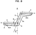
- the connecting plate 5 is shown in Fig. 1B schematically, it is practically formed with a member having sufficient strength and extending over the rear sides of the first and second antenna plates as illustrated in Fig. 8 which will be discussed later with reference to another embodiment.
- the first and second antenna plates are substantially rectangular plane antennae coupled at their respective sides to opposite end edges of the connecting plate.
- Each of the antenna plates has a beam axis usually perpendicular to its plane so that it receives most efficiently the radio wave with an angle of incidence parallel to the beam axis. Accordingly, each antenna is controlled for its orientation so that its beam axis lies coincident with the incident direction of the radio wave.
- the angle between each antenna plate and the connecting plate is referred to as tilt angle.
- the tilt angle represents an angle in excess of right angle between a plane including the edges of the antenna plates coupled to the connecting plate, namely the plane representing the connecting plate, and the plane of the antenna plate. Accordingly, when the angle formed by the antenna plate and the connecting plate is right angle, the tilt angle is 0.
- Fig. 1B shows an example, in which the tilt angle ⁇ x is 0.
- each of the first antenna plate 3 and the second antenna plate 4 is connected to the connecting plate 5 with a certain tilt angle ⁇ x .
- the tilt angle ⁇ x is selected so as to avoid overlapping of the first antenna plate 3 with the second antenna plate 4, as viewed in the direction of the beam axis, over a practical driving range in rotation of the antenna unit A in the elevation direction.
- the tilt angle ⁇ x is selected to be greater than or equal to 0°.
- Japanese practical drive angle range of 23° - 53° the tilt angle is appropriately selected from a range of 0° to 40°.
- the drive angle represents an angle of the beam axis of the antenna unit relative to a horizontal line.
- a pivot shaft 6 is provided at the intermediate portion of the connecting plate 5 so that the antenna unit A is pivotally driven about the pivot shaft 6 in the elevation direction by means of an elevation motor 7.
- the antenna unit A and the elevation motor 7 are mounted on a bearing plate 10 fixed to a rotary base 8.
- the rotary shaft of the rotary base 8 is supported rotatably on the bearing plate 10 through a bearing 12.
- a belt 13 with teeth which is made of a rubber is secured on the circumference of the rotary base 6.
- the belt 13 is wrapped around a gear 30 secured on a rotary shaft of an azimuth motor 14 which is fixedly secured to the casing 1. Therefore, the rotary base 8 is driven to rotate in the azimuth direction over 360° relative to the casing 1 by revolution of the azimuth motor 14.
- receiver circuits 16 including RF converters and BS tuners are arranged on the reverse surfaces of the first and second antenna plates 3 and 4.
- the amounts of rotations of the antenna unit A in the azimuth and elevation directions, respectively are determined.
- the output of the receiver circuit 16, the control signal for the elevation motor 7 and the power are transmitted through a slip ring 15.
- a cut out 21 is formed on the rotary base 8.
- the tip end of the second antenna plate 4 reaches a point below the rotary base 8 at its lower-most position as driven about the rotary shaft 6 by the elevation motor, as shown by broken line in Fig. 1B.
- the first antenna plate 3 is separated into two plane antennas X and Y in the azimuth direction.
- the second antenna plate 4 is formed of a single plane antenna Z. Based on the phase difference between the output signals of the plane antennas X and Y of the first antenna plate, a drive signal in the azimuth direction (rotational direction about axis 11) is obtained.
- a drive signal for the elevation direction is obtained. As shown in Fig.
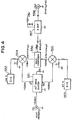
- the signals from the plane antennas X, Y and Z are supplied to the RF converter 16.
- the RF converter 16 includes RF amplifiers 161, 162 and 163, mixer/IF amplifiers 164, 165 and 166, and a local oscillator 167 formed of a dielectric resonator.
- the outputs from the three plane antennas X, Y and Z are partially divided by wave dividers 171, 172 and 173, subjected to simple composition and in-phase composition by wave composers 181 and 182 and then supplied to an external tuner through a booster 183 and a rotary coupling antenna 184.
- the error signal processing circuit 50 comprises an IF amplifier circuit 5a including BS tuners 51, 52 and 53, an error signal detector circuit 5b including phase detectors 58A and 58B.
- the output signals of the three plane antennas X, Y and Z divided by the wave dividers 171, 172 and 173 are converted into the second intermediate frequency (approximately 403 Hz) by the BS tuners 51, 52 and 53.
- the phase detector circuit 58A has an input terminal, to which the output signal of the BS tuner 51 is input through the wave divider, and an input terminal, to which the output signal of the BS tuner 52 is input through a phase correction circuit 55 and the wave divider.
- the phase detector 58A generates an azimuth error signal indicative of an argument between the horizontal component of the beam axis direction of the antenna unit, i.e. direction of the antenna unit and the horizontal component of the incident direction of the radio wave on the basis of the phase difference of both input signals.
- the output signal of the BS tuner 51 is combined by the wave composer 59 with a signal derived by phase correction of the output signal of the BS tuner 52 by the phase correction circuit 55 and then supplied to one input terminal of the phase detection circuit 58B.
- the phase detector circuit 58B has another input terminal, to which the output signal of the BS tuner 53 is supplied after subjected to phase correction by the phase correction circuit 56.
- the phase detector circuit 58B generates an elevation error signal indicative of an argument between the elevation direction component of the beam axis of the antenna unit and the elevation direction component of the incident direction of the radio wave.
- the azimuth error signal and the elevation error signal are supplied to a drive control circuit 60 including CPU 60A and a D/A converter 60B.
- CPU 60A derives driving directions of the azimuth motor 14 and the elevation motor 7 on the basis of the azimuth error signal and the elevation error signal to drive the azimuth motor 14 and the elevation motor 7 through an azimuth motor drive circuit 61 and an elevation motor drive circuit 62, respectively, so as to adjust the beam axis direction of the antenna unit to be consistent with the incident direction of the radio wave.
- CPU 60A calculates phase differences ⁇ 1, ⁇ 2 and ⁇ 3 among the received radio waves of the plane antennas X, Y and Z and supplies to the phase correction circuits 55, 56 and 57.
- phase correction circuits 57, 55 and 56 are provided upstream of the wave divider 173 and downstream of the tuners 52 and 53, respectively, for phase-shifting the input signal Sin ⁇ t by ⁇ thereby to obtain a signal ASin( ⁇ t + ⁇ ).
- a generally represents ⁇ 1, ⁇ 2 and ⁇ 3 calculated by CPU.
- Each of the phase correction circuits 55, 56 and 57 comprises a 90°-wave divider 551 for dividing the input signal into two signals with 90° phase difference, D/A converters 552 and 553 converting digital cosine signal and digital sine signal supplied from CPU of the control circuit 60 into analog signals, a mixer 554 for mixing composing a signal having no phase difference with the input signal output from the 90° wave divider 551 and the cosine signal, a mixer 555 for composing a signal having 90° phase difference to the input signal output from the 90° wave divider and the sine signal, a wave composer 556 for composing the outputs of both mixers, and an amplifier 557.
- signal delay magnitude can be set by CPU in digital value. This permits automatic adjustment of signal delay magnitude due to difference of the signal line length.
- the antenna unit A is pivotally driven in the elevation direction about the rotary shaft 6. According to pivotal motion, the tip end of the first antenna plate 3 rises, and conversely, the tip end of the second antenna plate 4 is lowered.
- the connecting plate 5 connecting both antenna plates is 2L
- the connecting plate 5 which rotates about a rotating axis P (it is assumed that the rotating axis P is located at a center of the connecting plate 5)
- the height of the highest point X1 of the second antenna plate relative to the rotating axis P is h1
- the height of the lowest point X2 relative to the rotating axis P is h2
- the elevation angle ⁇ is in a range of 38° - 15° to 38° + 15°, namely 23° to 53°.
- Table 1 shows variation of the total height H when the length 2L of the connection plate 5 is varied.
- the point to satisfy the minimum height condition at both of the minimum angle 23° and the maximum angle 53° is the point where the height calculated with respect to 23° becomes smaller than the calculated height with respect to 53°.
- the total height becomes 173 mm. This height is 33% lower than the height of the single plate antenna, i.e. 258 mm.
- the total height H becomes 131 mm. This is 33% lower than the case of the single-plate antenna, i.e. 195 mm, and 25% lower than the case of the two-plate antenna with no tilt angle, i.e.
- the second embodiment is different from the first embodiment in that the position of the rotary shaft 6 for rotation in the direction of elevation is shifted from the center of the connecting plate 5 toward the first antenna plate 3.
- the center for rotation in the elevation direction By shifting the center for rotation in the elevation direction, the total height can be lowered from Hh1 to Hh2, and the spacial efficiency of the antenna can be increased thereby making the casing compact.
- the third embodiment of the antenna apparatus of the present invention will be described below with reference to Figs. 8, 9 and 10.
- the antenna unit A includes the first antenna plate 3 and the second antenna plate 4 connected to the connecting plate 5 with an angle of 90° + a tilt angle ⁇ x .
- the rotating axis of the antenna unit A for rotation in the elevation direction is offset toward the first antenna plate 3 similarly to the second embodiment.
- RF converters 16A are fixedly mounted on the rear sides of the first and second antenna plates 3 and 4, RF converters 16A are fixedly mounted.
- the BS tuner 5a is fixedly mounted.
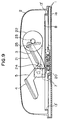
- Fig. 9 is a partial section of the antenna apparatus to be used for explaining manner of pivotally driving the antenna unit A in the elevation direction.
- Fig. 10 is a plan view of the antenna apparatus to be used for explaining the manner of pivotally driving the antenna unit in the elevation direction and that in the azimuth direction.
- the elevation motor 7 is fixed to a rotary base 8. On the rotary shaft of the elevation motor 7, a pulley 20 is mounted for co-rotation therewith. The driving torque of the elevation motor 7 is transmitted from the pulley 20 to a pulley 22 through a drive belt 21.
- a pinion gear 23 is provided in coaxial with the pulley 22.
- a rack 25 having teeth formed along a circle about the rotating axis 24 in the elevation direction of the antenna unit A On the side of the first antenna plate 3 is fixed, a rack 25 having teeth formed along a circle about the rotating axis 24 in the elevation direction of the antenna unit A.
- the teeth of the rack 25 is meshed with the pinion gear 23 to be driven circumferentially by the driving torque transmitted to the pinion gear.
- the antenna unit A is driven for rotation in the elevation direction.
- the driving torque of the elevation motor 7 is transmitted to the rack 25 through the pulley 20, the belt 21, the pulley 22 and the pinion gear 23 and thus the antenna unit A is driven for rotation in the elevation direction.
- the driving torque of the elevation motor 7 can be transmitted to the antenna unit A with appropriate reduction rate without providing complicate or bulky reduction gear unit, and thus permits positioning of the antenna unit with high precision.
- the azimuth motor 14 is fixed on the rotary base 8 via a sub-base 8b.
- a pulley 30 is fixed for rotation therewith.
- the pulley 30 is coupled with another pulley 32 via a drive belt 31.
- a pinion 33 is provided coaxially with the pulley 32.
- the pinion 33 is placed to mesh with the teeth of a belt 13' fixedly secured on the bottom plate 1a of the casing along its outer circumference.
- the driving torque of the azimuth motor 14 is thus transmitted through the pulleys 30 and 32, the drive belt 31 and the pinion 33 to the belt 13' with teeth which serves like a rack. Since the cogged belt 13' is rigidly secured on the casing 1, the rotary base 8 rotates relative to the casing 1 thereby varying the azimuth direction of the antenna unit A.
- the antenna apparatus employs the Z-shaped two-plate antenna construction.
- a distance between two antenna plates as viewed in the incident direction of radio wave to be received, or an apparent distance is set small so that the two antenna plates can be seen as if it is a single-plate antenna in the incident direction. Since the apparent distance between the antenna plates and the trace control range are proportional to each other, it facilitates control with wider trace control range when it is controlled within main lobe. Furthermore, when two antennas are simply positioned in close proximity, mutual interference may be caused. However, according to the present invention, since two antenna plates are positioned spaced apart by a given distance in a direction in which the antenna plates receive the radio wave with a certain phase difference, mutual interference is hardly caused.
Landscapes
- Engineering & Computer Science (AREA)
- Remote Sensing (AREA)
- Variable-Direction Aerials And Aerial Arrays (AREA)
- Details Of Aerials (AREA)
- Support Of Aerials (AREA)
- Input Circuits Of Receivers And Coupling Of Receivers And Audio Equipment (AREA)
Applications Claiming Priority (2)
| Application Number | Priority Date | Filing Date | Title |
|---|---|---|---|
| JP182031/91 | 1991-06-26 | ||
| JP3182031A JP2626686B2 (ja) | 1991-06-26 | 1991-06-26 | 移動体用アンテナ装置 |
Publications (3)
| Publication Number | Publication Date |
|---|---|
| EP0520424A2 true EP0520424A2 (fr) | 1992-12-30 |
| EP0520424A3 EP0520424A3 (en) | 1993-09-15 |
| EP0520424B1 EP0520424B1 (fr) | 1996-05-01 |
Family
ID=16111128
Family Applications (1)
| Application Number | Title | Priority Date | Filing Date |
|---|---|---|---|
| EP92110669A Expired - Lifetime EP0520424B1 (fr) | 1991-06-26 | 1992-06-25 | Appareil d'antenne pour un corps en mouvement |
Country Status (8)
| Country | Link |
|---|---|
| US (1) | US5420598A (fr) |
| EP (1) | EP0520424B1 (fr) |
| JP (1) | JP2626686B2 (fr) |
| KR (1) | KR960007561B1 (fr) |
| AT (1) | ATE137613T1 (fr) |
| CA (1) | CA2071269C (fr) |
| DE (1) | DE69210313T2 (fr) |
| ES (1) | ES2086583T3 (fr) |
Cited By (6)
| Publication number | Priority date | Publication date | Assignee | Title |
|---|---|---|---|---|
| EP0668625A1 (fr) * | 1994-02-22 | 1995-08-23 | TELECO S.r.l. | Antenne pour véhicules à dispositif d'auto alignement vers un satellite |
| ES2113809A1 (es) * | 1995-10-20 | 1998-05-01 | Video Bus Paher S A | Antena polivalente multidirecional de aplicacion a vehiculos en general. |
| EP1804333A1 (fr) * | 2006-01-03 | 2007-07-04 | Harris Corporation | Système d'antenne à profil bas et procédés associés |
| EP2025040A4 (fr) * | 2005-10-16 | 2009-08-05 | Starling Advanced Comm Ltd | Antenne a profil bas |
| US8964891B2 (en) | 2012-12-18 | 2015-02-24 | Panasonic Avionics Corporation | Antenna system calibration |
| US9583829B2 (en) | 2013-02-12 | 2017-02-28 | Panasonic Avionics Corporation | Optimization of low profile antenna(s) for equatorial operation |
Families Citing this family (21)
| Publication number | Priority date | Publication date | Assignee | Title |
|---|---|---|---|---|
| JPH08195614A (ja) * | 1994-11-16 | 1996-07-30 | Japan Radio Co Ltd | 追尾型アレイアンテナ装置 |
| US6259415B1 (en) | 1996-06-03 | 2001-07-10 | Bae Systems Advanced Systems | Minimum protrusion mechanically beam steered aircraft array antenna systems |
| KR20010020377A (ko) * | 1997-04-30 | 2001-03-15 | 크리스티안 그레그와르 | 이동 위성을 지시하기 위한 안테나 시스템 |
| US6204823B1 (en) | 1999-03-09 | 2001-03-20 | Harris Corporation | Low profile antenna positioner for adjusting elevation and azimuth |
| US6195060B1 (en) | 1999-03-09 | 2001-02-27 | Harris Corporation | Antenna positioner control system |
| US6738024B2 (en) * | 2001-06-22 | 2004-05-18 | Ems Technologies Canada, Ltd. | Mechanism for differential dual-directional antenna array |
| US6407714B1 (en) * | 2001-06-22 | 2002-06-18 | Ems Technologies Canada, Ltd. | Mechanism for differential dual-directional antenna array |
| WO2004069153A2 (fr) * | 2003-01-27 | 2004-08-19 | Medrad, Inc. | Appareil, systeme et procede de generation de bulles sur demande |
| IL154525A (en) | 2003-02-18 | 2011-07-31 | Starling Advanced Comm Ltd | Low profile satellite communications antenna |
| US6873301B1 (en) | 2003-10-07 | 2005-03-29 | Bae Systems Information And Electronic Systems Integration Inc. | Diamond array low-sidelobes flat-plate antenna systems for satellite communication |
| JP2005195529A (ja) * | 2004-01-09 | 2005-07-21 | Japan Radio Co Ltd | レーダ装置 |
| US7015866B1 (en) | 2004-03-26 | 2006-03-21 | Bae Systems Information And Electronic Systems Integration Inc. | Flush-mounted air vehicle array antenna systems for satellite communication |
| IL174549A (en) | 2005-10-16 | 2010-12-30 | Starling Advanced Comm Ltd | Dual polarization planar array antenna and cell elements therefor |
| CN104466342B (zh) * | 2014-12-11 | 2017-04-12 | 中国电子科技集团公司第五十四研究所 | 一种天线自动折叠液压集成装置 |
| KR101694261B1 (ko) * | 2015-09-09 | 2017-01-23 | 현대자동차주식회사 | 안테나 장치 및 상기 안테나 장치를 이용하는 차량 |
| EP3480890A1 (fr) * | 2017-11-06 | 2019-05-08 | Thomson Licensing | Dispositif d'amélioration dynamique de la puissance d'un signal sans fil |
| US11942689B2 (en) | 2018-05-24 | 2024-03-26 | Nanowave Technologies Inc. | RADAR antenna system and method |
| US11977144B2 (en) | 2018-05-24 | 2024-05-07 | Nanowave Technologies Inc. | System and method for improved radar sensitivity |
| US11233325B2 (en) * | 2020-02-07 | 2022-01-25 | Panasonic Avionics Corporation | Antenna assembly |
| DE102021101423B3 (de) * | 2021-01-22 | 2022-03-03 | Tesat-Spacecom Gmbh & Co. Kg | Schwenkmechanismus für Kommunikationseinheiten |
| KR102480508B1 (ko) * | 2022-02-23 | 2022-12-22 | 주식회사 지티엘 | 위성 추종기능을 구비한 위성 안테나 포지셔너 |
Family Cites Families (9)
| Publication number | Priority date | Publication date | Assignee | Title |
|---|---|---|---|---|
| FR1228144A (fr) * | 1959-03-02 | 1960-08-26 | Csf | Nouvel ensemble de balayage tridimensionnel |
| US4295621A (en) * | 1980-03-18 | 1981-10-20 | Rca Corporation | Solar tracking apparatus |
| JPH01261005A (ja) * | 1988-04-12 | 1989-10-18 | Nippon Steel Corp | アンテナ装置 |
| CA1318394C (fr) * | 1988-04-12 | 1993-05-25 | Ryuichi Hiratsuka | Systeme d'antennes et methode d'asservissement en altitude |
| JP2902407B2 (ja) * | 1989-03-24 | 1999-06-07 | 新日本製鐵株式会社 | アンテナ装置 |
| JP2641544B2 (ja) * | 1988-12-13 | 1997-08-13 | 新日本製鐵株式会社 | 受信アンテナの姿勢制御方法および装置 |
| US4994812A (en) * | 1988-12-13 | 1991-02-19 | Nippon Steel Corporation | Antenna system |
| JPH02202102A (ja) * | 1989-01-30 | 1990-08-10 | Nec Home Electron Ltd | ビームチルト型平面アレイアンテナ |
| JPH03247003A (ja) * | 1990-02-23 | 1991-11-05 | Matsushita Electric Works Ltd | 衛星放送受信用自動追尾アンテナシステム |
-
1991
- 1991-06-26 JP JP3182031A patent/JP2626686B2/ja not_active Expired - Lifetime
-
1992
- 1992-06-15 CA CA002071269A patent/CA2071269C/fr not_active Expired - Fee Related
- 1992-06-25 EP EP92110669A patent/EP0520424B1/fr not_active Expired - Lifetime
- 1992-06-25 ES ES92110669T patent/ES2086583T3/es not_active Expired - Lifetime
- 1992-06-25 AT AT92110669T patent/ATE137613T1/de not_active IP Right Cessation
- 1992-06-25 DE DE69210313T patent/DE69210313T2/de not_active Expired - Fee Related
- 1992-06-25 US US07/904,028 patent/US5420598A/en not_active Expired - Fee Related
- 1992-06-26 KR KR1019920011298A patent/KR960007561B1/ko not_active Expired - Fee Related
Cited By (7)
| Publication number | Priority date | Publication date | Assignee | Title |
|---|---|---|---|---|
| EP0668625A1 (fr) * | 1994-02-22 | 1995-08-23 | TELECO S.r.l. | Antenne pour véhicules à dispositif d'auto alignement vers un satellite |
| ES2113809A1 (es) * | 1995-10-20 | 1998-05-01 | Video Bus Paher S A | Antena polivalente multidirecional de aplicacion a vehiculos en general. |
| EP2025040A4 (fr) * | 2005-10-16 | 2009-08-05 | Starling Advanced Comm Ltd | Antenne a profil bas |
| EP1804333A1 (fr) * | 2006-01-03 | 2007-07-04 | Harris Corporation | Système d'antenne à profil bas et procédés associés |
| US7453409B2 (en) | 2006-01-03 | 2008-11-18 | Harris Corporation | Low profile antenna system and associated methods |
| US8964891B2 (en) | 2012-12-18 | 2015-02-24 | Panasonic Avionics Corporation | Antenna system calibration |
| US9583829B2 (en) | 2013-02-12 | 2017-02-28 | Panasonic Avionics Corporation | Optimization of low profile antenna(s) for equatorial operation |
Also Published As
| Publication number | Publication date |
|---|---|
| CA2071269A1 (fr) | 1992-12-27 |
| DE69210313D1 (de) | 1996-06-05 |
| JPH057108A (ja) | 1993-01-14 |
| KR960007561B1 (ko) | 1996-06-05 |
| DE69210313T2 (de) | 1996-12-19 |
| CA2071269C (fr) | 1997-06-10 |
| JP2626686B2 (ja) | 1997-07-02 |
| EP0520424B1 (fr) | 1996-05-01 |
| ES2086583T3 (es) | 1996-07-01 |
| ATE137613T1 (de) | 1996-05-15 |
| US5420598A (en) | 1995-05-30 |
| EP0520424A3 (en) | 1993-09-15 |
Similar Documents
| Publication | Publication Date | Title |
|---|---|---|
| EP0520424B1 (fr) | Appareil d'antenne pour un corps en mouvement | |
| US4760402A (en) | Antenna system incorporated in the air spoiler of an automobile | |
| US5309162A (en) | Automatic tracking receiving antenna apparatus for broadcast by satellite | |
| JP3313636B2 (ja) | 低軌道衛星通信用アンテナ装置 | |
| US4994812A (en) | Antenna system | |
| JPH09270634A (ja) | 移動体sng装置 | |
| JP3002612B2 (ja) | 電波到来方位・偏波計測用アンテナ装置、電波到来方位・偏波計測装置及びアンテナ指向装置 | |
| JP2641544B2 (ja) | 受信アンテナの姿勢制御方法および装置 | |
| JPH09246844A (ja) | 追尾装置 | |
| EP1099274B1 (fr) | Dispositif pour systemes d'antennes | |
| JP3084344B2 (ja) | 移動体衛星通信用車載アンテナ | |
| JPH066593Y2 (ja) | 多周波共用アンテナ | |
| JP3176805B2 (ja) | 移動体用衛星通信アンテナ装置 | |
| JPH06331720A (ja) | モノパルスアンテナ | |
| JPH0653738A (ja) | 衛星用アンテナ | |
| US5977903A (en) | Scanning mechanism for vehicle- mounted radar | |
| CA2164545A1 (fr) | Antenne de station terrienne mobile | |
| KR20160143039A (ko) | 차량용 위성 안테나 | |
| KR200360034Y1 (ko) | 이동수신용 다중채널 위성 안테나 | |
| JPH08307136A (ja) | 衛星自動追尾アンテナ装置 | |
| KR200217326Y1 (ko) | 이동체 탑재 위성안테나 장치 | |
| JPH07235822A (ja) | 自動追尾アンテナ装置 | |
| CA2121229C (fr) | Systeme d'antennes | |
| JPH08256006A (ja) | アンテナ装置 | |
| JP3253984B2 (ja) | 航空機用衛星放送受信装置 |
Legal Events
| Date | Code | Title | Description |
|---|---|---|---|
| PUAI | Public reference made under article 153(3) epc to a published international application that has entered the european phase |
Free format text: ORIGINAL CODE: 0009012 |
|
| AK | Designated contracting states |
Kind code of ref document: A2 Designated state(s): AT DE ES FR GB IT |
|
| PUAL | Search report despatched |
Free format text: ORIGINAL CODE: 0009013 |
|
| AK | Designated contracting states |
Kind code of ref document: A3 Designated state(s): AT DE ES FR GB IT |
|
| 17P | Request for examination filed |
Effective date: 19931209 |
|
| 17Q | First examination report despatched |
Effective date: 19950821 |
|
| GRAH | Despatch of communication of intention to grant a patent |
Free format text: ORIGINAL CODE: EPIDOS IGRA |
|
| GRAA | (expected) grant |
Free format text: ORIGINAL CODE: 0009210 |
|
| AK | Designated contracting states |
Kind code of ref document: B1 Designated state(s): AT DE ES FR GB IT |
|
| PG25 | Lapsed in a contracting state [announced via postgrant information from national office to epo] |
Ref country code: AT Effective date: 19960501 |
|
| REF | Corresponds to: |
Ref document number: 137613 Country of ref document: AT Date of ref document: 19960515 Kind code of ref document: T |
|
| REF | Corresponds to: |
Ref document number: 69210313 Country of ref document: DE Date of ref document: 19960605 |
|
| REG | Reference to a national code |
Ref country code: ES Ref legal event code: FG2A Ref document number: 2086583 Country of ref document: ES Kind code of ref document: T3 |
|
| ITF | It: translation for a ep patent filed | ||
| ET | Fr: translation filed | ||
| PLBE | No opposition filed within time limit |
Free format text: ORIGINAL CODE: 0009261 |
|
| STAA | Information on the status of an ep patent application or granted ep patent |
Free format text: STATUS: NO OPPOSITION FILED WITHIN TIME LIMIT |
|
| 26N | No opposition filed | ||
| PGFP | Annual fee paid to national office [announced via postgrant information from national office to epo] |
Ref country code: ES Payment date: 19970613 Year of fee payment: 6 |
|
| PGFP | Annual fee paid to national office [announced via postgrant information from national office to epo] |
Ref country code: GB Payment date: 19970616 Year of fee payment: 6 |
|
| PGFP | Annual fee paid to national office [announced via postgrant information from national office to epo] |
Ref country code: FR Payment date: 19970624 Year of fee payment: 6 |
|
| PGFP | Annual fee paid to national office [announced via postgrant information from national office to epo] |
Ref country code: DE Payment date: 19970828 Year of fee payment: 6 |
|
| PG25 | Lapsed in a contracting state [announced via postgrant information from national office to epo] |
Ref country code: GB Free format text: LAPSE BECAUSE OF NON-PAYMENT OF DUE FEES Effective date: 19980625 |
|
| PG25 | Lapsed in a contracting state [announced via postgrant information from national office to epo] |
Ref country code: ES Free format text: LAPSE BECAUSE OF EXPIRATION OF PROTECTION Effective date: 19980626 |
|
| GBPC | Gb: european patent ceased through non-payment of renewal fee |
Effective date: 19980625 |
|
| PG25 | Lapsed in a contracting state [announced via postgrant information from national office to epo] |
Ref country code: FR Free format text: LAPSE BECAUSE OF NON-PAYMENT OF DUE FEES Effective date: 19990226 |
|
| PG25 | Lapsed in a contracting state [announced via postgrant information from national office to epo] |
Ref country code: DE Free format text: LAPSE BECAUSE OF NON-PAYMENT OF DUE FEES Effective date: 19990401 |
|
| REG | Reference to a national code |
Ref country code: FR Ref legal event code: ST |
|
| REG | Reference to a national code |
Ref country code: ES Ref legal event code: FD2A Effective date: 20000301 |
|
| PG25 | Lapsed in a contracting state [announced via postgrant information from national office to epo] |
Ref country code: IT Free format text: LAPSE BECAUSE OF NON-PAYMENT OF DUE FEES;WARNING: LAPSES OF ITALIAN PATENTS WITH EFFECTIVE DATE BEFORE 2007 MAY HAVE OCCURRED AT ANY TIME BEFORE 2007. THE CORRECT EFFECTIVE DATE MAY BE DIFFERENT FROM THE ONE RECORDED. Effective date: 20050625 |