EP0520467A2 - Gyroscope de vibration - Google Patents
Gyroscope de vibration Download PDFInfo
- Publication number
- EP0520467A2 EP0520467A2 EP92110775A EP92110775A EP0520467A2 EP 0520467 A2 EP0520467 A2 EP 0520467A2 EP 92110775 A EP92110775 A EP 92110775A EP 92110775 A EP92110775 A EP 92110775A EP 0520467 A2 EP0520467 A2 EP 0520467A2
- Authority
- EP
- European Patent Office
- Prior art keywords
- vibrator
- vibratory gyroscope
- vibrating body
- supporting
- supporting members
- Prior art date
- Legal status (The legal status is an assumption and is not a legal conclusion. Google has not performed a legal analysis and makes no representation as to the accuracy of the status listed.)
- Granted
Links
Images



Classifications
-
- G—PHYSICS
- G01—MEASURING; TESTING
- G01C—MEASURING DISTANCES, LEVELS OR BEARINGS; SURVEYING; NAVIGATION; GYROSCOPIC INSTRUMENTS; PHOTOGRAMMETRY OR VIDEOGRAMMETRY
- G01C19/00—Gyroscopes; Turn-sensitive devices using vibrating masses; Turn-sensitive devices without moving masses; Measuring angular rate using gyroscopic effects
- G01C19/56—Turn-sensitive devices using vibrating masses, e.g. vibratory angular rate sensors based on Coriolis forces
- G01C19/5642—Turn-sensitive devices using vibrating masses, e.g. vibratory angular rate sensors based on Coriolis forces using vibrating bars or beams
- G01C19/5663—Manufacturing; Trimming; Mounting; Housings
Definitions
- the present invention relates to a vibratory gyroscope, and particularly to a vibratory gyroscope which is capable of measuring a rotational angular velocity by utilizing, for example, a bending and vibration mode, and is used, for example, in a navigation system installed in an automobile.
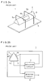
- Fig. 24 is a perspective view showing an example of a conventional vibratory gyroscope which is a background of the present invention
- Fig. 25 is a circuit diagram thereof.
- the vibratory gyroscope 1 comprises a vibrator 2.
- the vibrator 2 includes a triangular prism-shaped vibrating body 3, on three side faces of the vibrating body 3, piezoelectric elements 4a, 4b and 4c are formed respectively.
- supporting members 5a and 5b consisting of a material such as nickel or the like are fixed.
- the supporting members 5a and 5b are fixed to the vicinity of nodal points of the vibrating body 3 by means of soldering, welding or the like.
- the supporting members 5a and 5b are fixed to a board 6 by means of soldering or the like.
- the supporting members 5a and 5b support the vibrating body 3 above the board 6 in a vibratory fashion and also serve as wires for grounding.
- one piezoelectric element 4c of the vibrator 2 is electrically connected to an input terminal of an oscillation circuit 7, output terminals of the oscillation circuit 7 are electrically connected to the other two piezoelectric elements 4a and 4b.
- the vibrator 2 makes self-oscillation drive.
- the two piezoelectric elements 4a and 4b are also electrically connected respectively to two input terminals of a detection circuit 8 consisting of, for example, a differential amplifier.
- the vibrating body 3 bends and vibrates.
- the vibratory gyroscope 1 by applying a driving signal to the piezoelectric elements 4a and 4b, the vibrating body 3 bends and vibrates.
- the vibratory gyroscope 1 is rotated about an axial direction of the vibrating body 3, voltages are generated in the piezoelectric elements 4a and 4b responsive thereto. And hence, by measuring the voltages generated in the piezoelectric elements 4a and 4b, a rotational angular velocity can be detected.
- the rotational angular velocity of the vibratory gyroscope 1 is detected by an output of the detection circuit 8.
- the supporting members are designed to support the vibrating body and to serve as the wires for grounding. And hence, as a conductive substance having a solderability and a weldability, a metal wire such as nickel is used.
- nickel or the like is relatively mild, thus when a thin wire material is used, the mechanical strength thereof is weakened.
- the vibration of the vibrating body may leak, or an outside vibration is transmitted through the supporting members, thereby deteriorating characteristics stability.
- the supporting members with a material having a large strength such as molybdenum.
- a material having a large strength such as molybdenum.
- such material is difficult to be soldered or welded and can not support the vibrating body.
- the vibrator is susceptible to an outside magnetism and its characteristics is deteriorated by the outside magnetism.
- a vibratory gyroscope comprises a prism-shaped vibrating body, a plurality of piezoelectric elements formed on side faces of the vibrating body, and a supporting member having a multi-layer structure and fixed to the vicinity of nodal point of the vibrating body, wherein an inner portion of the supporting member being formed by an elastic material having a large strength, and an outer portion thereof being formed by a material having a good solderability.
- the supporting member can be soldered to the vibrating body and a board. Furthermore, by using the elastic material having the large strength as the inner portion of the supporting member, the supporting member can support the vibrating body even when the supporting member is made thinner. Besides, since the supporting member is deformed elastically, the vibration of the vibrating body is not hindered.
- the vibrating body can be supported by such thin supporting member, the vibration of the vibrating body never leaks from the supporting member, nor the outside vibration is transmitted to the vibrating body through the supporting member. Besides, the supporting member itself will never hinder the vibration of the vibrating body. Thus, characteristics of the vibratory gyroscope can be stabilized. Meanwhile, since the supporting member can be fixed to the vibrating body and the board, the vibrating body can be supported above the board reliably.
- An another vibratory gyroscope according to the present invention comprises a vibrator, and a shield member consisting of a material having a magnetism and provided around the vibrator.
- the vibrator is magnetically shielded from the outside by the shield material.
- a heater may be provided in the vicinity of the vibrator.
- the heater is provided in the vicinity of the vibrator as such, the temperature of the vibrator is kept stable by the heater. And hence, characteristic deterioration of the vibratory gyroscope due to the outside temperature change is restrained.
- a cushion material may be provided around the vibrator.
- the cushion material is provided around the vibrator as such, the vibrator is adiabatically isolated from the outside by the cushion material. Besides, an unnecessary sound wave to the vibrator from the outside is absorbed by the cushion material. And hence, characteristics of the vibratory gyroscope is stabilized against the outside temperature change and sound wave.
- an oscillation circuit for driving the vibrator may be provided, and further, a shield cover consisting of a material having a magnetism may be disposed so as to cover the oscillation circuit.
- a shield cover consisting of a material having a magnetism may be disposed so as to cover the oscillation circuit.
- a shield cover which serves as a ground potential, and a back cover which is electrically connected to the shield cover may be provided.
- one of the shield cover and the back cover may be formed with an elastic material, and the back cover may be pressed onto the shield cover against its elastic force.
- the back cover When the back cover is pressed onto the shield cover which serves as the ground potential as such, the shield cover and the back cover are electrically connected. And hence, the vibratory gyroscope can be connected to the outside ground potential easily. Meanwhile, the back cover may be electrically connected to the shield cover simply by just pressing the back cover onto the shield cover.
- a third vibratory gyroscope comprises a vibrator, a supporting member for supporting the vibrator, and a protective member provided in the vicinity of, at least, one of the vibrator and the supporting member.
- the supporting member is not displaced unnecessarily by the protective member, thereby the supporting member for supporting the vibrator is hardly exposed to plastic deformation.
- the vibrator may be disposed on one side of a circuit board, and an oscillation circuit for driving the vibrator and an detection circuit for detecting the vibrator displacement may be disposed on the other side of the circuit board, and further, an intermediate board having terminals which extend through the circuit board may be disposed.
- the vibrator, the oscillation circuit and the detection circuit may be electrically connected through the terminals of the intermediate board.
- a lead wire is not needed to be stretched from one side to the other side of the circuit board.
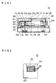
- Fig. 1 is a front illustrative view showing one embodiment of the present invention.
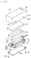
- Fig. 2 is a side illustrative view of a vibratory gyroscope shown in Fig. 1.
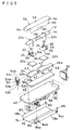
- Fig. 3 is an exploded view of the vibratory gyroscope shown in Fig. 1.
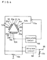
- Fig. 4 is a circuit diagram of the vibratory gyroscope shown in Fig. 1.
- Fig. 5 is an exploded view showing an essential portion of the vibratory gyroscope shown in Fig. 1.
- Fig. 6 is a sectional view of a supporting member used in the vibratory gyroscope shown in Fig. 1.
- Fig. 7 is a front illustrative view showing a structure for supporting a vibrator of the vibratory gyroscope shown in Fig. 1.
- Fig. 8 is a side illustrative view showing a structure for supporting the vibrator of the vibratory gyroscope shown in Fig. 1.
- Fig. 9 is a front view of a supporting plate used in the vibratory gyroscope shown in Fig. 1.
- Fig. 10 is a plan view of the supporting plate shown in Fig. 9.
- Fig. 11 is a side view of the supporting plate shown in Fig. 9.
- Fig. 12 is a front view of a work cover used in the vibratory gyroscope shown in Fig. 1.
- Fig. 13 is a plan view of the work cover shown in Fig. 12.
- Fig. 14 is a side view of the work cover shown in Fig. 12.
- Fig. 15 is a front view of a shield cover used in the vibratory gyroscope shown in Fig. 1.
- Fig. 16 is a plan view of the shield cover shown in Fig. 15.
- Fig. 17 is a side view of the shield cover shown in Fig. 15.
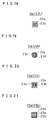
- Fig. 18 is a sectional view showing a modified example of the supporting member shown in Fig. 6.
- Fig. 19 is a sectional view showing another modified example of the supporting member shown in Fig. 6.
- Fig. 20 is a sectional view showing a modified example of the supporting member shown in Fig. 19.
- Fig. 21 is a sectional view showing still another modified example of the supporting member shown in Fig. 6.
- Fig. 22 is a perspective view showing another embodiment of the present invention.
- Fig. 23 is a side view of the embodiment shown in Fig. 22.
- Fig. 24 is a perspective view showing an example of a conventional vibratory gyroscope which is a background of the present invention.
- Fig. 25 is a circuit diagram of the vibratory gyroscope shown in Fig. 24.
- Fig. 1 is a front illustrative view showing one embodiment of the present invention
- Fig. 2 is a side illustrative view thereof
- Fig. 3 is an exploded view of a vibratory gyroscope shown in Fig. 1.
- Fig. 4 is a circuit diagram of the vibratory gyroscope shown in Fig. 1.
- Fig. 5 is an exploded view showing an essential portion of the vibratory gyroscope shown in Fig. 1.
- the vibratory gyroscope 10 comprises a vibrator 12.
- the vibrator 12 includes, for example, a regular triangular prism-shaped vibrating body 14 as particularly shown in Fig. 5.
- the vibrating body 14 is formed with a constant elastic metal material such as nickel, iron, chromium, titanium or their alloys such as elinver, Fe-Ni alloy.
- the vibrating body 14 may be formed with a material which generally generates a mechanical vibration such as quartz, glass, crystal, ceramics besides metal.
- piezoelectric elements 16a, 16b and 16c are respectively secured to the center portions of its three side faces.
- the piezoelectric elements 16a-16c respectively include piezoelectric layers 18 consisting of, for example, ceramics, and on both surfaces of the piezoelectric layers 18, electrodes 20a and 20b are formed respectively.
- the electrodes 20a on one surface of the piezoelectric elements 16a-16c are bonded to the side faces of the vibrating body 14 by means of, for example, a conductive adhesive.
- the two piezoelectric elements 16a and 16b are used for vibrating and driving the vibrating body 14 and for detecting displacement of the vibrating body 14, and the other piezoelectric element 16c is used for feeding back the driving signal to the two piesoelectric elements 16a and 16b.
- the vibrator 12 is, as particularly shown in Fig. 5, supported by two U-shaped supporting members 22a and 22b.
- the supporting members 22a and 22b are, as shown in Fig. 6, respectively formed into a double-layer structure having a circular section.
- a material of inner portions 23a of the supporting members 22a and 22b an elastic material having a large strength such as molybdenum, tungsten, titanium or the like is used, and as a material of outer portions 23b thereof, a material having a good solderability and weldability such as nickel, platinum, gold, silver, copper, stainless steel, iron or the like is used.
- the supporting members may be formed by a single material.
- center portions of the supporting members 22a and 22b are secured to ridge-line portions of the vibrating body 14 between the two piezoelectric elements 16a and 16b.
- the supporting members 22a and 22b are secured to the vicinity of nodal points of the vibrating body 14 so as not to affect negatively on the vibration of the vibrating body 14.
- the supporting members 22a and 22b are secured to the positions of 0.224L from opposite ends of the vibrating body 14, where L represents the length of vibrating body 14.
- the supporting members 22a and 22b are, for example, soldered or welded to the vibrating body 14.
- the supporting members 22a and 22b may be bonded and secured to the vibrating body 14 by means of an adhesive.
- Both end portions of the supporting members 22a and 22b are, as shown in Fig. 5, Fig. 7 and Fig. 8, respectively secured to substantially rectangular stationary plates 24a and 24b consisting of a metal material such as iron, nickel, stainless steel or the like. That is, two holes 26 are respectively formed in the stationary plates 24a and 24b. The both end portions of one supporting member 22a are inserted through the two holes 26 of one stationary plate 24a and soldered thereto. Similarly, the both end portions of the other supporting member 22b are inserted through the two holes 26 of the other stationary plate 24b and soldered thereto.
- substantially U-shaped piece members 28 are formed respectively so as not to touch the vibrator 12.
- plate-shaped protective members 30 are formed respectively.
- the protective members 30 are designed to protect the supporting members 22a and 22b by not allowing the supporting members 22a and 22b to displace in a lateral direction of the vibrator 12 unnecessarily, and are disposed in the vicinity of the supporting members 22a and 22b, for example, inner sides of the supporting members 22a and 22b.
- the piece members 28 and the protective members 30 are formed integrally with the stationary plates 24a and 24b.
- the stationary plates 24a and 24b are, as shown in Fig. 1 and Fig. 5, respectively secured to, for example, one surface of a flat-shaped supporting plate 34 consisting of a material having a magnetism and conductivity such as iron, nickel, stainless steel or the like, for example, by buffer materials 32a and 32b.
- leg members 36a and 36b which extend downward from one end and the other end in its longitudinal direction are formed.
- a projection 38 is formed at its lower end center.
- two projections 40a and 40b are formed on both sides at the other end in the longitudinal direction of the supporting plate 34. The projections 38, 40a and 40b are used for securing the supporting plate 34 to a circuit board 46 to be described later.
- two hold pieces 42 are formed at a predetermined distance at one end in its lateral direction, and at the other end in its lateral direction, two hold pieces 42 are formed at a predetermined distance.
- the hold pieces 42 are used for holding a work cover 56 to be described later by the supporting plate 34.
- a PTC (positive temperature coefficient) element 44 is fixed.
- the PTC element 44 is designed to keep the temperature of the vibrator 12 stable. That is, a fixed voltage is applied to the PTC element 44.
- a resistance of the PTC element 44 increases and a calorific value therefrom is reduced to lower the peripheral temperature, on the contrary, when the peripheral temperature is low, the resistance in the PTC element 44 reduces and the calorific value therefrom is increased to raise the peripheral temperature.
- the temperature of the vibrator 12 is kept stable by the PTC element 44.
- the supporting plate 34 is fixed to one surface side of the circuit board 46 as shown in Fig. 3 and Fig. 5.
- the projection 38 of the leg member 36a on one end side of the supporting plate 34 is inserted through the circuit board 46, and soldered to a ground pattern (not shown) on the other surface of the circuit board 46.
- the supporting plate 34 is secured to the circuit board 46 in the floating state from one surface of the circuit board 46 by the two leg members 36a and 36b.
- a sheet-shaped cushion material 48 is bonded to the center of one surface of the circuit board 46 by means of an adhesive.
- the cushion material 48 is formed with a material consisting of rubber such as butyl rubber or a synthetic resin such as urethane, which is foamed such that respective cells do not cohere to each other or foamed into closed cells.
- a U-shaped intermediate board 50 is fixed out of the other end in the longitudinal direction of the supporting plate 34.
- three terminals 52a, 52b and 52c which are in parallel to its surface and extend outwardly are formed in parallel to each other.
- the terminals 52a-52c are extended through the circuit board 46 and respectively soldered to three conductive patterns (not shown) on the other surface of the circuit board 46.
- the intermediate board 50 is secured to the circuit board 46 such that, its one surface faces the end face of the other end side in the longitudinal direction of the supporting plate 34.
- the two projections 40a and 40b of the supporting plate 34 are inserted through the intermediate board 50 and soldered to a conductive pattern (not shown) on the other surface of the intermediate plate 50.
- the supporting plate 34 is further secured tightly to the circuit board 46 via the intermediate board 50.
- the other surface of the intermediate board 50 three conductive patterns 54a, 54b and 54c are formed, and the three terminals 52a-52c are electrically connected respectively to the conductive patterns 54a-54c.
- the electrodes 20b on the other surface of the three piezoelectric elements 16a-16c of the vibrator 12 are electrically connected respectively by means of lead wires (not shown).
- the work cover 56 consisting of a material having a magnetism and a conductivity such as iron, nickel, stainless steel or the like is installed to the supporting plate 34 so as to cover the vibrator 12, the intermediate board 50 and so on.
- the work cover 56 includes a flat-shaped surface member 58 as shown in Fig. 5, Fig. 12, Fig. 13 and Fig. 14, and on the surface member 58, side members 60 which extend downward from its lateral ends are formed respectively. Lower end center portions of the side members 60 are formed as projections 62 which project outwardly.
- protective members 64 having an L-shaped section are respectively formed at longitudinal ends on the surface member 58. The work cover 56 is placed in such a manner that, its side members 60 are engaged to the inner side of the hold pieces 42 of the supporting plate 34, and the projections 62 of the side members 60 are engaged between the hold pieces 42, 42. In this case, the two protective members 64 are disposed in the vicinity of the outer opposite ends in the longitudinal direction of the vibrator 12.
- the protective members 64 are designed to protect the supporting members 22a and 22b, by not allowing the vibrator 12 to displace in its longitudinal direction unnecessarily, or by not allowing the supporting members 22a and 22b to displace in the longitudinal direction of the vibrator 12 unnecessarily.
- an oscillation circuit 66 and a detection circuit 68 are mounted on the other surface of the circuit board 46.
- the oscillation circuit 66 is for driving and vibrating the vibrator 12, and includes a crystal for stabilizing the oscillation frequency and a phase correcting circuit for adjusting the oscillation frequency.
- An input terminal of the oscillation circuit 66 is, as particularly shown in Fig. 4, electrically connected to the electrode 20b of the piezoelectric element 16c of the vibrator 12 via the conductive pattern (not shown), the terminal 52c of the intermediate board 50 and so on, and an output terminal of the oscillation circuit 66 is divided by a variable resistor 72a and are respectively connected to the electrodes 20b of the piezoelectric elements 16a and 16b via the other conductive pattern (not shown), the terminals 52a , 52b and so on.
- the detection circuit 68 is for detecting displacement of the vibrator 12 and is consisting of, for example, a differential amplifier or the like. Two input terminals of the detection circuit 68 are respectively connected to the electrodes 20b of the piezoelectric elements 16a and 16b via the conductive pattern (not shown), the terminals 52a, 52b and so on.
- variable resistors 72a, 72b and 72c are mounted on the other surface of the circuit board 46.
- One variable resistor 72a is designed to distribute an output of the oscillation circuit equally to the piezoelectric elements 16a and 16b.
- the another variable resistor 72b is designed to adjust an input signal level inputted to the detection circuit 68 and, as shown in Fig. 4, is connected between the two input terminals of the detection circuit 68.
- the third or more another variable resistor 72c is designed to adjust an output signal level of the detection circuit 68, and is connected between the output terminal of the detection circuit 68 and a grounding.
- a shield cover 74 consisting of a material having a magnetism, conductivity and elasticity such as iron, nickel, stainless steel or the like is installed so as to cover the oscillation circuit 66, the detection circuit 68, the variable resistors 72a, 72b, 72c and so on.
- the shield cover 74 includes a rectangular plate-shaped surface member 76 having a substantially same width as the circuit board 46 as shown in Fig. 5, Fig. 15, Fig. 16 and Fig. 17.
- the surface member 76 has its center portion in the lateral direction bent outwardly.
- side members 78a and 78b are formed respectively.
- projections 80 are formed respectively. The projections 80 are inserted through the circuit board 46 and soldered to a ground pattern (not shown) on one surface of the circuit board 46.
- a plurality of terminals 86 such as a power terminal for supplying an electric power to the oscillation circuit 66 and the detection circuit 68, and an output terminal for taking out the output signal of the detection circuit 68 are formed upward, the terminals 86 are connected to the PTC element 44, the oscillation circuit 66 and detection circuit 68 via the conductive pattern (not shown) of the circuit board 46 and so on.
- the vibrator 12, the circuit board 46, the work cover 56 and so on are contained in a box case 92 together with two cushion materials 88 and 90 as shown in Fig. 1 and Fig. 3.
- the cushion material 88 is formed into, for example, a rectangular plate shape, and disposed on the upper face of the work cover 56. A hole associated with the work cover 56 is formed at the center of the cushion material 90. The cushion material 90 is disposed on the side of the work cover 56.
- the cushion materials 88 and 90 are formed with a material consisting of rubber such as butyl rubber or a synthetic resin such as urethane, which is foamed such that respective cells do not cohere to each other, as same as the aforementioned cushion material 48.
- the cushion materials 48, 88 and 90 are designed to enhance a heat shield between the circumference of the vibrator 12 and the outside to absorb an unnecessary sound wave from the outside to the vibrator 12 and to prevent the leakage of vibration from the vibrator 12 to the outside.
- an opening portion 94 associated with the terminals 86 is formed, and as particularly shown in Fig. 2, the terminals 86 are exposed out of the case 92.
- a rectangular plate-shaped back cover 98 consisting of a conductor such as aluminum or the like is fixed by means of screws 100.
- the back cover 98 is pressed onto the shield cover 74 against its elastic force and is electrically connected to the shield cover 74.
- a driving signal is applied to the piezoelectric elements 16a and 16b by the oscillation circuit 66, thereby the vibrating body 14 bends and vibrates.
- the vibrating body 14 bends and vibrates in a direction orthogonal to the face whereon the piezoelectric element 16c is formed.
- the vibrating direction is changed by a Coriolis force.
- Voltages are generated in the piezoelectric elements 16a and 16b responsive thereto.
- the supporting members 22a and 22b can be made finer.
- the vibration of the vibrating body 14 hardly leaks from the supporting members 22a and 22b, or an outside vibration is hardly transmitted to the vibrating body 14 through the supporting members 22a and 22b.
- the material of the inner portions 23a of the supporting members 22a and 22b is subjected to elastic deformation, it does not hinder the vibration of the vibrating body 14. And hence, the vibrating state as well as characteristics of the vibratory gyroscope 10 are stabilized.
- connection to the vibrating body 14 and connection to the stationary plates 24a and 24b are effected reliably by means of soldering or welding.
- the supporting members 22a and 22b may be formed into the other shape such as a quadrangular sectional shape. Even in such shape, when the elastic material having a large strength is used in the inner portion 23a and the material having a good solderability and weldability is used in the outer portion 23b, the same effect can be obtained. Meanwhile, as shown in Fig. 19 and Fig. 20, the supporting members 22a and 22b may be constructed in a multi-layer structure such as a three-layer structure.
- the elastic material having a large strength such as molybdenum may be used in the inner portion 23a
- the metal material such as nickel is used in the outer portion 23b
- a solder layer may be formed as an outermost layer 23c.
- the outer portion 23b of the supporting members 22a and 22b may not necessarily by formed around the inner portion 23a, it may be formed partially at a necessary portion only such as opposing surfaces of the inner portion 23a as shown in Fig. 21. As such, the shape and multi-layer structure of the supporting members 22a and 22b can be changed freely responsive to the purposes.
- the supporting members 22a and 22b are bent in opposite directions with each other in a longitudinal direction of the vibrating body 14, at the same time, the stationary plates 24a and 24b are displaced separately. And hence, the supporting members 22a and 22b do not interfere one another, thus the vibration of the vibrating body 14 is not suppressed by the supporting members 22a and 22b. Thus, a stable vibration attitude of the vibrating body 14 can be secured.
- the protective members 30 are provided in the inner vicinity of the supporting members 22a and 22b for supporting the vibrator 12, the supporting members 22a and 22b are not displaced unnecessarily in a lateral direction of the vibrator 12, and hardly caused to plastic deformation. And hence, characteristic deterioration due to the plastic deformation of the supporting members 22a and 22b is prevented. Furthermore, since the supporting members 22a and 22b are not displaced unnecessarily in the longitudinal direction of the vibrator 12, by the protective members 64 of the work cover 56 which are disposed in the outer vicinity of longitudinal opposite ends of the vibrator 12, the characteristic deterioration due to the plastic deformation of the supporting members 22a and 22b is prevented.
- the protective members may be provided in the vicinity of the vibrator 12 or the supporting members 22a and 22b, and a shape of the protective member is not limited to a plate but may be formed into a block.
- the cushion materials, 48, 88 and 90 consisting of the material which has closed cells are disposed around the vibrator 12, the heat shield between the circumference of the vibrator 12 and the outside is good, and an unnecessary sound wave to the vibrator 12 from the outside can be absorbed, and further, the vibration leakage from the vibrator 12 to the outside can be prevented. And hence, the characteristic deterioration due to the outside temperature change and the sound wave from the outside can be prevented, and at the same time, the vibration leakage from the vibrator 12 to an external device can be prevented.
- the temperature of the vibrator 12 can be kept stable. And hence, characteristic deterioration due to the temperature change can be restrained.
- the other heater such as an NTC (negative temperature coefficient) element, a Nichrome (trademark) wire, a ceramic heater or the like may be disposed in the vicinity of the vibrator 12 in place of the PTC element 44, and further, a temperature detecting means such as a bimetal for detecting peripheral temperature of the vibrator 12 may be disposed to switch on and off the heater based upon the detection by the temperature detecting means.
- the vibrator 12 is magnetically shielded from the outside, and characteristic deterioration due to the outside magnetism can be prevented.
- the vibrator 12 provided on one side of the circuit board 46 is electrically connected to the oscillation circuit 66 and the detection circuit 68 on the other side of the circuit board 46 via the terminals 52a-52c of the intermediate board 50, it is not necessary to stretch a lead wire from one side to the other side of the circuit board 46.
- the shield cover 74 consisting of a material having a magnetism is provided so as to cover the oscillation circuit 66 and so on, a high-frequency noise generated from the oscillation circuit 66 can be prevented.
- the back cover 98 is electrically connected to the shield cover 74 which serves as a ground potential, it is easy to connect to the outside ground potential.
- the back cover 98 is simply connected electrically to the shield cover 74 just by pressing onto the shield cover 74 against the elastic force of the shield cover 74.
- one of the shield cover 74 and the back cover 98 may be formed with a material having an elasticity so as to press the back cover 98 onto the shield cover 74 against its elastic force.
- Fig. 22 is a perspective view showing another embodiment of the present invention
- Fig. 23 is a side view thereof.
- the vibratory gyroscope 10 comprises a vibrator 12 (a vibrating body 14 and piezoelectric elements 16a to 16c) and supporting members 22a and 22b which are similar to the embodiment shown in Fig. 1.
- the vibratory gyroscope 10 comprises a supporting stand 120 consisting of a material such as metal, ceramics or the like.
- a buffer material 122 consisting of an elastic material such as rubber, sponge or the like is bonded.
- two boards 124 and 126 which are divided in its longitudinal direction are bonded.
- five electrodes 128a, 128b, 128c, 128d and 128e are formed in a spaced relationship in its lateral direction.
- electrodes 130a and 130b are formed at opposite ends in its lateral direction.
- opposite ends of the supporting member 22a are secured by means of soldering, welding or the like.
- opposite ends of the other supporting member 22b are respectively secured to the electrodes 130a and 130b on the other board 126.
- the supporting members 22a and 22b support the vibrating body 14 and also serve as grounding wires.
- the piezoelectric elements 16a, 16b and 16c are electrically connected respectively by means of, for example, the lead wires.
- the vibrating body 14 bends and vibrates. In this case, the vibrating body 14 bends and vibrates in a direction orthogonal to the case whereon the piezoelectric element 16c is formed.
- the vibrating direction changes due to a Coriolis force. Voltages are generated in the piezoelectric elements 16a and 16c responsive thereto.
- a rotational angular velocity applied to the vibratory gyroscope 10 can be measured.
- the supporting members 22a and 22b can be made finer.
- vibration of the vibrating body 14 never leaks from the supporting members 22a and 22b, or an outside vibration is hardly transmitted to the vibrating body 14 through the supporting members 22a and 22b.
- the material of the inner portions 23a of the supporting members 22a and 22b deforms elastically, it does not hinder the vibration of the vibrating body 14. And hence, the vibration state of the vibratory gyroscope 10 as well as characteristics are stabilized.
- connection with the vibrating body 14 and connection with the electrodes 128a, 128e and 130a, 130b are effected reliably by means of soldering and welding.
- the supporting members 22a and 22b bend in opposite directions with each other in a longitudinal direction of the vibrating body 14, at the same time, the boards 124 and 126 which are divided also displace separately. And hence, the supporting members 22a and 22b do not interfere one another, and the vibration of the vibrating body 14 is not suppressed by the supporting members 22a and 22b. Thus, a stable vibration attitude of the vibrating body 14 can be secured.
- the piezoelectric elements are respectively formed on three side faces of the vibrating body 14, the driving and detecting piezoelectric elements may be respectively formed only on two side faces of the vibrating body 14.
- the vibrating body 14 may also by formed into a polygonal prism shape such as a quadrangular prism shape besides the triangular prism shape.
- the piezoelectric elements may just be formed on two or more side faces of the vibrating body.
Landscapes
- Engineering & Computer Science (AREA)
- Manufacturing & Machinery (AREA)
- Physics & Mathematics (AREA)
- General Physics & Mathematics (AREA)
- Radar, Positioning & Navigation (AREA)
- Remote Sensing (AREA)
- Gyroscopes (AREA)
Applications Claiming Priority (16)
| Application Number | Priority Date | Filing Date | Title |
|---|---|---|---|
| JP185269/91 | 1991-06-28 | ||
| JP3185269A JPH0510763A (ja) | 1991-06-28 | 1991-06-28 | 振動ジヤイロ |
| JP3194915A JPH0518756A (ja) | 1991-07-08 | 1991-07-08 | 振動ジヤイロ |
| JP3194919A JPH0518760A (ja) | 1991-07-08 | 1991-07-08 | 振動ジヤイロ |
| JP3194917A JPH0518758A (ja) | 1991-07-08 | 1991-07-08 | 振動ジヤイロ |
| JP194917/91 | 1991-07-08 | ||
| JP194918/91 | 1991-07-08 | ||
| JP3194913A JPH0518754A (ja) | 1991-07-08 | 1991-07-08 | 振動ジヤイロ |
| JP194913/91 | 1991-07-08 | ||
| JP3194918A JPH0518759A (ja) | 1991-07-08 | 1991-07-08 | 振動ジヤイロ |
| JP194915/91 | 1991-07-08 | ||
| JP194916/91 | 1991-07-08 | ||
| JP3194916A JP2666617B2 (ja) | 1991-07-08 | 1991-07-08 | 振動ジャイロ |
| JP3194914A JPH0518755A (ja) | 1991-07-08 | 1991-07-08 | 振動ジヤイロ |
| JP194919/91 | 1991-07-08 | ||
| JP194914/91 | 1991-07-08 |
Publications (3)
| Publication Number | Publication Date |
|---|---|
| EP0520467A2 true EP0520467A2 (fr) | 1992-12-30 |
| EP0520467A3 EP0520467A3 (en) | 1993-06-23 |
| EP0520467B1 EP0520467B1 (fr) | 1996-01-03 |
Family
ID=27573367
Family Applications (1)
| Application Number | Title | Priority Date | Filing Date |
|---|---|---|---|
| EP92110775A Expired - Lifetime EP0520467B1 (fr) | 1991-06-28 | 1992-06-26 | Gyroscope de vibration |
Country Status (3)
| Country | Link |
|---|---|
| US (1) | US5345822A (fr) |
| EP (1) | EP0520467B1 (fr) |
| DE (1) | DE69207282T2 (fr) |
Cited By (16)
| Publication number | Priority date | Publication date | Assignee | Title |
|---|---|---|---|---|
| EP0606602A1 (fr) * | 1993-01-08 | 1994-07-20 | Murata Manufacturing Co., Ltd. | Structure de support pour vibreur |
| EP0660081A1 (fr) * | 1993-12-21 | 1995-06-28 | Murata Manufacturing Co., Ltd. | Gyroscope à vibration |
| EP0664439A1 (fr) * | 1994-01-21 | 1995-07-26 | Murata Manufacturing Co., Ltd. | Gyroscope vibrant |
| EP0678730A1 (fr) * | 1994-04-21 | 1995-10-25 | Matsushita Electric Industrial Co., Ltd. | Dispositif capteur de vitesse angulaire |
| EP0715149A1 (fr) * | 1994-12-02 | 1996-06-05 | Murata Manufacturing Co., Ltd. | Gyroscope d'oscillation |
| EP0715148A1 (fr) * | 1994-12-02 | 1996-06-05 | Murata Manufacturing Co., Ltd. | Gyroscope d'oscillation |
| US5675083A (en) * | 1994-12-15 | 1997-10-07 | Murata Manufacturing Co., Ltd. | Vibrating gyroscope having divided detection elements |
| US5693998A (en) * | 1995-03-31 | 1997-12-02 | Murata Manufacturing Co., Ltd. | Oscillation gyroscope |
| EP0747667A3 (fr) * | 1995-06-07 | 1998-02-25 | Murata Manufacturing Co., Ltd. | Gyroscope à vibration |
| EP0751375A3 (fr) * | 1995-06-26 | 1998-04-15 | Murata Manufacturing Co., Ltd. | Gyroscope à vibration |
| US5751093A (en) * | 1995-03-14 | 1998-05-12 | Murat Manufacturing Co., Ltd. | Vibrating gyroscope |
| US5773915A (en) * | 1995-08-08 | 1998-06-30 | Murata Manufacturing Co., Ltd. | Vibrating gyroscope |
| EP0768514A3 (fr) * | 1995-10-11 | 1998-07-01 | Murata Manufacturing Co., Ltd. | Gyroscope à vibration |
| US5912528A (en) * | 1995-04-03 | 1999-06-15 | Murata Manufacturing Co., Ltd. | Vibrating gyroscope |
| EP0684450B1 (fr) * | 1994-05-23 | 2000-06-21 | Murata Manufacturing Co., Ltd. | Structure de support d'un vibreur |
| EP1189026A4 (fr) * | 2000-03-17 | 2006-07-05 | Matsushita Electric Industrial Co Ltd | Capteur angulaire et procede de fabrication de ce capteur |
Families Citing this family (17)
| Publication number | Priority date | Publication date | Assignee | Title |
|---|---|---|---|---|
| US5493166A (en) * | 1988-08-12 | 1996-02-20 | Murata Manufacturing Co., Ltd. | Vibrator and vibrating gyroscope using the same |
| US5874674A (en) * | 1988-08-12 | 1999-02-23 | Murata Manufacturing Co., Ltd. | Vibrator including piezoelectric electrodes or detectors arranged to be non-parallel and non-perpendicular to coriolis force direction and vibratory gyroscope using the same |
| JP3166889B2 (ja) * | 1993-12-16 | 2001-05-14 | 株式会社村田製作所 | 振動ジャイロ |
| JP3178212B2 (ja) * | 1993-12-28 | 2001-06-18 | 株式会社村田製作所 | 発振回路 |
| JP3211562B2 (ja) * | 1994-05-12 | 2001-09-25 | 株式会社村田製作所 | 圧電振動子 |
| JP2736023B2 (ja) * | 1994-12-27 | 1998-04-02 | ユニデン株式会社 | バイブレータ取付構造、バイブレータ取付用保持具、および、バイブレータ取付方法 |
| US5698784A (en) * | 1996-01-24 | 1997-12-16 | Gyration, Inc. | Vibratory rate gyroscope and methods of assembly and operation |
| RU2104557C1 (ru) * | 1996-07-26 | 1998-02-10 | Товарищество с ограниченной ответственностью Фирма "Кварк" | Вибрационный датчик угловой скорости |
| JPH10197255A (ja) * | 1997-01-10 | 1998-07-31 | Sony Corp | 角速度センサー |
| US6655215B2 (en) * | 2001-06-15 | 2003-12-02 | Honeywell International Inc. | Inverse corner cube for non-intrusive three axis vibration measurement |
| JP2005214878A (ja) * | 2004-01-30 | 2005-08-11 | Sony Corp | 角速度センサ |
| JP4428309B2 (ja) * | 2004-09-10 | 2010-03-10 | セイコーエプソン株式会社 | 振動型ジャイロスコープ |
| US8327526B2 (en) * | 2009-05-27 | 2012-12-11 | The Boeing Company | Isolated active temperature regulator for vacuum packaging of a disc resonator gyroscope |
| CN102278983B (zh) * | 2011-07-22 | 2014-03-26 | 上海交通大学 | 具有三角形振子的硅微陀螺仪及其制作方法 |
| JP5798864B2 (ja) * | 2011-09-29 | 2015-10-21 | エスアイアイ・クリスタルテクノロジー株式会社 | 圧電振動子、発振器、電子機器、および電波時計 |
| CN104215235B (zh) * | 2013-06-05 | 2017-08-22 | 北京信息科技大学 | 一种新型钟形振子式角速率陀螺 |
| US20160349053A1 (en) | 2015-06-01 | 2016-12-01 | Analog Devices, Inc. | Micromachined Resonating Beam Gyroscopes |
Family Cites Families (11)
| Publication number | Priority date | Publication date | Assignee | Title |
|---|---|---|---|---|
| US3316768A (en) * | 1963-10-29 | 1967-05-02 | Thiokol Chemical Corp | Magnetic angular velocity indicating system |
| AU522709B2 (en) * | 1980-09-22 | 1982-06-24 | Sundstrand Data Control, Inc. | Accelerometer protective structure |
| US4750362A (en) * | 1983-07-05 | 1988-06-14 | Litton Systems Inc. | Accelerometer package |
| US4854169A (en) * | 1987-06-15 | 1989-08-08 | Japan Aviation Electronics Industry Ltd. | Accelerometer |
| GB2208318B (en) * | 1987-07-24 | 1991-11-06 | Yazaki Corp | Vibrational angular velocity sensor |
| US4836023A (en) * | 1988-03-09 | 1989-06-06 | Yazaki Corporation | Vibrational angular rate sensor |
| DE3926504C2 (de) * | 1988-08-12 | 1999-11-18 | Murata Manufacturing Co | Schwingkreisel |
| CA1330265C (fr) * | 1988-09-23 | 1994-06-21 | Craig W. White | Accelerometre a etalonnage automatique |
| JPH02306111A (ja) * | 1989-05-19 | 1990-12-19 | Matsushita Electric Ind Co Ltd | 角速度検出装置 |
| US5130600A (en) * | 1989-06-02 | 1992-07-14 | Mitsubishi Petrochemical Co., Ltd. | Acceleration sensor |
| EP0477540B1 (fr) * | 1990-08-27 | 1995-08-09 | Murata Manufacturing Co., Ltd. | Circuit de détection pour gyroscope de vibration |
-
1992
- 1992-06-24 US US07/903,317 patent/US5345822A/en not_active Expired - Fee Related
- 1992-06-26 DE DE69207282T patent/DE69207282T2/de not_active Expired - Fee Related
- 1992-06-26 EP EP92110775A patent/EP0520467B1/fr not_active Expired - Lifetime
Cited By (21)
| Publication number | Priority date | Publication date | Assignee | Title |
|---|---|---|---|---|
| EP0606602A1 (fr) * | 1993-01-08 | 1994-07-20 | Murata Manufacturing Co., Ltd. | Structure de support pour vibreur |
| EP0807802A1 (fr) * | 1993-12-21 | 1997-11-19 | Murata Manufacturing Co., Ltd. | Gyroscope à vibration |
| EP0660081A1 (fr) * | 1993-12-21 | 1995-06-28 | Murata Manufacturing Co., Ltd. | Gyroscope à vibration |
| EP0664439A1 (fr) * | 1994-01-21 | 1995-07-26 | Murata Manufacturing Co., Ltd. | Gyroscope vibrant |
| US5581032A (en) * | 1994-04-21 | 1996-12-03 | Matsushita Electric Industrial Co., Ltd. | Angular velocity sensor device |
| EP0678730A1 (fr) * | 1994-04-21 | 1995-10-25 | Matsushita Electric Industrial Co., Ltd. | Dispositif capteur de vitesse angulaire |
| EP0684450B1 (fr) * | 1994-05-23 | 2000-06-21 | Murata Manufacturing Co., Ltd. | Structure de support d'un vibreur |
| EP0715148A1 (fr) * | 1994-12-02 | 1996-06-05 | Murata Manufacturing Co., Ltd. | Gyroscope d'oscillation |
| EP0715149A1 (fr) * | 1994-12-02 | 1996-06-05 | Murata Manufacturing Co., Ltd. | Gyroscope d'oscillation |
| US6242848B1 (en) | 1994-12-02 | 2001-06-05 | Murata Manufacturing Co., Ltd. | Oscillation gyroscope |
| US5675083A (en) * | 1994-12-15 | 1997-10-07 | Murata Manufacturing Co., Ltd. | Vibrating gyroscope having divided detection elements |
| US5751093A (en) * | 1995-03-14 | 1998-05-12 | Murat Manufacturing Co., Ltd. | Vibrating gyroscope |
| US5693998A (en) * | 1995-03-31 | 1997-12-02 | Murata Manufacturing Co., Ltd. | Oscillation gyroscope |
| US5912528A (en) * | 1995-04-03 | 1999-06-15 | Murata Manufacturing Co., Ltd. | Vibrating gyroscope |
| EP0747667A3 (fr) * | 1995-06-07 | 1998-02-25 | Murata Manufacturing Co., Ltd. | Gyroscope à vibration |
| US5895999A (en) * | 1995-06-07 | 1999-04-20 | Murata Manufacturing Co., Ltd. | Vibrating gyroscope |
| EP0751375A3 (fr) * | 1995-06-26 | 1998-04-15 | Murata Manufacturing Co., Ltd. | Gyroscope à vibration |
| US5773915A (en) * | 1995-08-08 | 1998-06-30 | Murata Manufacturing Co., Ltd. | Vibrating gyroscope |
| US5889358A (en) * | 1995-10-11 | 1999-03-30 | Murata Manufacturingco., Ltd. | Vibration gyroscope |
| EP0768514A3 (fr) * | 1995-10-11 | 1998-07-01 | Murata Manufacturing Co., Ltd. | Gyroscope à vibration |
| EP1189026A4 (fr) * | 2000-03-17 | 2006-07-05 | Matsushita Electric Industrial Co Ltd | Capteur angulaire et procede de fabrication de ce capteur |
Also Published As
| Publication number | Publication date |
|---|---|
| DE69207282T2 (de) | 1996-08-29 |
| EP0520467A3 (en) | 1993-06-23 |
| EP0520467B1 (fr) | 1996-01-03 |
| DE69207282D1 (de) | 1996-02-15 |
| US5345822A (en) | 1994-09-13 |
Similar Documents
| Publication | Publication Date | Title |
|---|---|---|
| EP0520467B1 (fr) | Gyroscope de vibration | |
| US5668316A (en) | Vibrating gyroscope | |
| KR100906178B1 (ko) | 진동자의 지지 구조 및 물리량 측정 장치 | |
| EP2947422B1 (fr) | Capteur de vitesse angulaire | |
| US6199429B1 (en) | Vibrating gyroscope with elastic vibration isolator | |
| US7234352B2 (en) | Angular velocity senor | |
| US6880399B1 (en) | Angular velocity sensor | |
| US11231277B2 (en) | Sensor device including angular velocity sensor element and acceleration sensor element | |
| JPH0518755A (ja) | 振動ジヤイロ | |
| US6694813B2 (en) | Vibrating gyroscope and electronic unit using the same | |
| CN1879007B (zh) | 振动式陀螺仪 | |
| JPH08159779A (ja) | 振動ジャイロ | |
| JPH0518754A (ja) | 振動ジヤイロ | |
| JP2666617B2 (ja) | 振動ジャイロ | |
| JP3082663B2 (ja) | 振動ジャイロ | |
| JP3275597B2 (ja) | 振動ジャイロ | |
| JPH0518760A (ja) | 振動ジヤイロ | |
| JPH0518756A (ja) | 振動ジヤイロ | |
| JPH0518759A (ja) | 振動ジヤイロ | |
| JPH08159778A (ja) | 振動ジャイロ | |
| JPH0518758A (ja) | 振動ジヤイロ | |
| EP0592987B1 (fr) | Gyromètre vibrant | |
| JPH05296772A (ja) | 振動ジャイロ | |
| JPH0854244A (ja) | 振動ジャイロ | |
| JPH05322581A (ja) | 振動ジャイロ |
Legal Events
| Date | Code | Title | Description |
|---|---|---|---|
| PUAI | Public reference made under article 153(3) epc to a published international application that has entered the european phase |
Free format text: ORIGINAL CODE: 0009012 |
|
| AK | Designated contracting states |
Kind code of ref document: A2 Designated state(s): DE FR GB IT SE |
|
| PUAL | Search report despatched |
Free format text: ORIGINAL CODE: 0009013 |
|
| AK | Designated contracting states |
Kind code of ref document: A3 Designated state(s): DE FR GB IT SE |
|
| 17P | Request for examination filed |
Effective date: 19930908 |
|
| 17Q | First examination report despatched |
Effective date: 19941021 |
|
| GRAA | (expected) grant |
Free format text: ORIGINAL CODE: 0009210 |
|
| AK | Designated contracting states |
Kind code of ref document: B1 Designated state(s): DE FR GB IT SE |
|
| ITF | It: translation for a ep patent filed | ||
| REF | Corresponds to: |
Ref document number: 69207282 Country of ref document: DE Date of ref document: 19960215 |
|
| ET | Fr: translation filed | ||
| PLBE | No opposition filed within time limit |
Free format text: ORIGINAL CODE: 0009261 |
|
| STAA | Information on the status of an ep patent application or granted ep patent |
Free format text: STATUS: NO OPPOSITION FILED WITHIN TIME LIMIT |
|
| 26N | No opposition filed | ||
| REG | Reference to a national code |
Ref country code: GB Ref legal event code: IF02 |
|
| PGFP | Annual fee paid to national office [announced via postgrant information from national office to epo] |
Ref country code: SE Payment date: 20050607 Year of fee payment: 14 |
|
| PGFP | Annual fee paid to national office [announced via postgrant information from national office to epo] |
Ref country code: FR Payment date: 20050608 Year of fee payment: 14 |
|
| PGFP | Annual fee paid to national office [announced via postgrant information from national office to epo] |
Ref country code: GB Payment date: 20050622 Year of fee payment: 14 |
|
| PGFP | Annual fee paid to national office [announced via postgrant information from national office to epo] |
Ref country code: DE Payment date: 20050623 Year of fee payment: 14 |
|
| PG25 | Lapsed in a contracting state [announced via postgrant information from national office to epo] |
Ref country code: GB Free format text: LAPSE BECAUSE OF NON-PAYMENT OF DUE FEES Effective date: 20060626 |
|
| PG25 | Lapsed in a contracting state [announced via postgrant information from national office to epo] |
Ref country code: SE Free format text: LAPSE BECAUSE OF NON-PAYMENT OF DUE FEES Effective date: 20060627 |
|
| PGFP | Annual fee paid to national office [announced via postgrant information from national office to epo] |
Ref country code: IT Payment date: 20060630 Year of fee payment: 15 |
|
| PG25 | Lapsed in a contracting state [announced via postgrant information from national office to epo] |
Ref country code: DE Free format text: LAPSE BECAUSE OF NON-PAYMENT OF DUE FEES Effective date: 20070103 |
|
| EUG | Se: european patent has lapsed | ||
| GBPC | Gb: european patent ceased through non-payment of renewal fee |
Effective date: 20060626 |
|
| REG | Reference to a national code |
Ref country code: FR Ref legal event code: ST Effective date: 20070228 |
|
| PG25 | Lapsed in a contracting state [announced via postgrant information from national office to epo] |
Ref country code: FR Free format text: LAPSE BECAUSE OF NON-PAYMENT OF DUE FEES Effective date: 20060630 |
|
| PG25 | Lapsed in a contracting state [announced via postgrant information from national office to epo] |
Ref country code: IT Free format text: LAPSE BECAUSE OF NON-PAYMENT OF DUE FEES Effective date: 20070626 |