EP0520593A1 - Appareil de commutation électrique multipolaire - Google Patents
Appareil de commutation électrique multipolaire Download PDFInfo
- Publication number
- EP0520593A1 EP0520593A1 EP92250148A EP92250148A EP0520593A1 EP 0520593 A1 EP0520593 A1 EP 0520593A1 EP 92250148 A EP92250148 A EP 92250148A EP 92250148 A EP92250148 A EP 92250148A EP 0520593 A1 EP0520593 A1 EP 0520593A1
- Authority
- EP
- European Patent Office
- Prior art keywords
- mounting rail
- pole
- switching device
- support
- legs
- Prior art date
- Legal status (The legal status is an assumption and is not a legal conclusion. Google has not performed a legal analysis and makes no representation as to the accuracy of the status listed.)
- Granted
Links
Images
Classifications
-
- H—ELECTRICITY
- H01—ELECTRIC ELEMENTS
- H01H—ELECTRIC SWITCHES; RELAYS; SELECTORS; EMERGENCY PROTECTIVE DEVICES
- H01H33/00—High-tension or heavy-current switches with arc-extinguishing or arc-preventing means
- H01H33/02—Details
- H01H33/022—Details particular to three-phase circuit breakers
Definitions
- the invention relates to a multi-pole electrical switching device, in particular a high-voltage circuit breaker with an essentially U-shaped mounting rail for a plurality of pole columns with support insulators.
- Such a multi-pole switching device is known for example from DE-U-87 17 789.
- a multi-pole electrical switching device is described, the pole columns of which are carried together by a pole plate.
- the pole plate is stabilized by support profiles attached to it.
- an essentially U-shaped profile is formed by the pole plate and the support profiles.
- the invention has for its object to provide a multi-pole electrical switching device with an Irish rail that is simple and economical to manufacture and on which the pole columns can be easily and securely attached.
- the pole columns should also be easily accessible in the area of the mounting rail.
- the mounting rail consists of a multiply folded one-piece sheet.
- the mounting rail can be manufactured quickly, easily and precisely from a flat sheet metal on a known folding device.
- the openings for screw fastenings and for the pole columns can be made in the sheet before folding, for example by punching or plasma cutting.
- the manufacture of the mounting rail is very inexpensive due to the simple folding process.
- the invention can advantageously be designed in that the free ends of the legs of the U-shaped mounting rail point toward the side facing away from the support insulators and that openings are provided on the side of the mounting rail facing the support insulators for receiving parts of the pole columns.
- Support bearings for the pole columns can advantageously be arranged on the side of the mounting rail facing the support insulators.
- the pole columns even if they are mounted on the mounting rail, are easily accessible from above and below for installation purposes. Due to the open profile shape of the mounting rail, the area of the pole columns is also below the mounting rail easily accessible.
- each pole column passing through the mounting rail is connected to the free ends of its legs on the side of the mounting rail facing away from the support insulators. This additional connection causes the free ends of the legs to form further support bearings for the pole columns.
- connection can be made, for example, by screwing.
- the connection can also be realized by a welded connection. It can prove to be advantageous to connect the part of the pole column to the free ends of the legs of the mounting rail by means of stable metallic webs or sheets. The connection becomes particularly stable when the free ends of the legs of the mounting rail are screwed directly to the pole column.
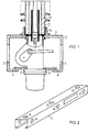
- the mounting rail 1 has two free legs 2, 3 which, after the sheet metal has been bent, protrude at right angles from the side 4 of the mounting rail 1 facing the support insulators and point with their free ends 5, 6 to the side facing away from the support insulators 13.
- the free ends 5, 6 are bent inwards again by folding.
- the mounting rail 1 thus forms a channel for receiving those parts of the pole columns 7 which protrude through openings 8, 9, 10 on the side 4 of the mounting rail 1 facing the support insulators 13.
- the free, bent ends 5, 6 of the legs 2, 3 of the mounting rail 1 are connected to the pole columns 7 via plates 11, 12. This results in greater rigidity of the mounting rail 1 against twisting and bending.
- the pole columns 7 are fastened to the side 4 of the mounting rail 1 facing the support insulators 13 by screws.
- the holes for the screws are already in the sheet metal of the mounting rail 1 before they are folded and are introduced either by punching, plasma cutting, milling or drilling, as are the openings for the pole columns 7.
- the free ends 5, 6 of the legs 2, 3 of the mounting rail 1 can be of such a length that they can be connected directly and without connecting plates 11, 12 to the pole columns 7 via screw connections. This facilitates the assembly of the switchgear.
- the typical sheet thickness for the mounting rail 1 is approximately 6 to 8 mm.
- engagement openings 15, 16, 17 are provided through which the Pole columns 7 are easily accessible from the outside in the area of the mounting rail.
Landscapes
- Power Conversion In General (AREA)
- Patch Boards (AREA)
- Rectifiers (AREA)
- Installation Of Bus-Bars (AREA)
- Control Of Motors That Do Not Use Commutators (AREA)
Applications Claiming Priority (2)
| Application Number | Priority Date | Filing Date | Title |
|---|---|---|---|
| DE9108176U | 1991-06-28 | ||
| DE9108176U DE9108176U1 (de) | 1991-06-28 | 1991-06-28 | Mehrpoliges elektrisches Schaltgerät |
Publications (2)
| Publication Number | Publication Date |
|---|---|
| EP0520593A1 true EP0520593A1 (fr) | 1992-12-30 |
| EP0520593B1 EP0520593B1 (fr) | 1997-03-19 |
Family
ID=6868912
Family Applications (1)
| Application Number | Title | Priority Date | Filing Date |
|---|---|---|---|
| EP92250148A Revoked EP0520593B1 (fr) | 1991-06-28 | 1992-06-12 | Appareil de commutation électrique multipolaire |
Country Status (3)
| Country | Link |
|---|---|
| EP (1) | EP0520593B1 (fr) |
| AT (1) | ATE150582T1 (fr) |
| DE (2) | DE9108176U1 (fr) |
Cited By (2)
| Publication number | Priority date | Publication date | Assignee | Title |
|---|---|---|---|---|
| WO2009010359A3 (fr) * | 2007-07-17 | 2009-03-26 | Siemens Ag | Montage comprenant un interrupteur coupe-charge et un interrupteur de mise à la terre |
| WO2019052796A1 (fr) * | 2017-09-18 | 2019-03-21 | Siemens Aktiengesellschaft | Support de base pour disjoncteur |
Citations (7)
| Publication number | Priority date | Publication date | Assignee | Title |
|---|---|---|---|---|
| DE682030C (de) * | 1937-02-28 | 1939-10-06 | Siemens Schuckertwerke Akt Ges | Fahrgestell fuer Schalter |
| DE2017836A1 (de) * | 1969-04-14 | 1970-10-15 | Switchgear and Equipment Ltd., Banbury, Oxford (Großbritannien) | Säulendrehs chalter |
| DE2009759B2 (de) * | 1970-03-03 | 1978-05-11 | Ruhrtal-Elektrizitaetsgesellschaft Hartig & Co, 4300 Essen | Trennschalter |
| DE2913379A1 (de) * | 1979-03-30 | 1980-10-02 | Siemens Ag | Mehrpoliges elektrisches schaltgeraet mit einem in den innenraum eines rohrfoermigen grundgestells hineinragenden montagekoerper |
| EP0030384A1 (fr) * | 1979-12-06 | 1981-06-17 | Licentia Patent-Verwaltungs-GmbH | Disjoncteur de haute tension à principe de commutation auto-pneumatique |
| US4752859A (en) * | 1985-04-10 | 1988-06-21 | S&C Electric Company | Arrangement for providing various circuit protection device configurations |
| DE9017055U1 (de) * | 1990-12-18 | 1991-03-07 | ABB Patent GmbH, 6800 Mannheim | Hochspannungsschalter mit Grundgestell |
-
1991
- 1991-06-28 DE DE9108176U patent/DE9108176U1/de not_active Expired - Lifetime
-
1992
- 1992-06-12 AT AT92250148T patent/ATE150582T1/de not_active IP Right Cessation
- 1992-06-12 DE DE59208218T patent/DE59208218D1/de not_active Revoked
- 1992-06-12 EP EP92250148A patent/EP0520593B1/fr not_active Revoked
Patent Citations (7)
| Publication number | Priority date | Publication date | Assignee | Title |
|---|---|---|---|---|
| DE682030C (de) * | 1937-02-28 | 1939-10-06 | Siemens Schuckertwerke Akt Ges | Fahrgestell fuer Schalter |
| DE2017836A1 (de) * | 1969-04-14 | 1970-10-15 | Switchgear and Equipment Ltd., Banbury, Oxford (Großbritannien) | Säulendrehs chalter |
| DE2009759B2 (de) * | 1970-03-03 | 1978-05-11 | Ruhrtal-Elektrizitaetsgesellschaft Hartig & Co, 4300 Essen | Trennschalter |
| DE2913379A1 (de) * | 1979-03-30 | 1980-10-02 | Siemens Ag | Mehrpoliges elektrisches schaltgeraet mit einem in den innenraum eines rohrfoermigen grundgestells hineinragenden montagekoerper |
| EP0030384A1 (fr) * | 1979-12-06 | 1981-06-17 | Licentia Patent-Verwaltungs-GmbH | Disjoncteur de haute tension à principe de commutation auto-pneumatique |
| US4752859A (en) * | 1985-04-10 | 1988-06-21 | S&C Electric Company | Arrangement for providing various circuit protection device configurations |
| DE9017055U1 (de) * | 1990-12-18 | 1991-03-07 | ABB Patent GmbH, 6800 Mannheim | Hochspannungsschalter mit Grundgestell |
Cited By (3)
| Publication number | Priority date | Publication date | Assignee | Title |
|---|---|---|---|---|
| WO2009010359A3 (fr) * | 2007-07-17 | 2009-03-26 | Siemens Ag | Montage comprenant un interrupteur coupe-charge et un interrupteur de mise à la terre |
| WO2019052796A1 (fr) * | 2017-09-18 | 2019-03-21 | Siemens Aktiengesellschaft | Support de base pour disjoncteur |
| CN111095463A (zh) * | 2017-09-18 | 2020-05-01 | 西门子股份公司 | 用于断路器的基础支架 |
Also Published As
| Publication number | Publication date |
|---|---|
| ATE150582T1 (de) | 1997-04-15 |
| DE59208218D1 (de) | 1997-04-24 |
| EP0520593B1 (fr) | 1997-03-19 |
| DE9108176U1 (de) | 1992-11-05 |
Similar Documents
| Publication | Publication Date | Title |
|---|---|---|
| EP2915215B1 (fr) | Ensemble de modules en série pourvu d'un système de bus d'énergie | |
| EP0010251A1 (fr) | Dispositif pour la fixation d'appareils d'installation | |
| EP1994614B1 (fr) | Construction a cadre pour une armoire electrique, armoire electrique et kit pour l'armoire electrique | |
| EP1441081B1 (fr) | Connecteur pour profilés et ensemble de connexion | |
| EP0594939A1 (fr) | Pied pour tables ou similaire | |
| EP0179198A2 (fr) | Bureau à structure métalique | |
| DE2838163A1 (de) | Zerlegbares rahmensystem | |
| EP1072179B1 (fr) | Support de modules | |
| EP0067970B1 (fr) | Dispositif de fixation pour éléments de façade | |
| EP0520593A1 (fr) | Appareil de commutation électrique multipolaire | |
| DE2657454C2 (de) | Variables Gehäusegerüst zum Einsatz in elektrotechnischen Anlagen | |
| EP2532799B1 (fr) | Support métallique et son utilisation | |
| AT403242B (de) | Befestigung für eine duschkabine an einer wand | |
| EP0620353A1 (fr) | Profil pour le renforcement extérieur d'un montant de fenêtre | |
| DE69925404T2 (de) | Metallische Verbindungsvorrichtung und Beschlagteile dafür | |
| DE29516040U1 (de) | Tragstütze sowie Tragvorrichtung mit wenigstens vier im Abstand zueinander angeordneten Tragstützen | |
| DE3248124A1 (de) | Elektrisches installationsgeraet mit einer vorrichtung zur seiner halterung auf zwei in einem abstand parallel zueinander verlaufenden profiltragschienen, insbesondere von hutprofilschienen | |
| DE4340965C1 (de) | Spinn- oder Zwirnmaschine | |
| EP1653579B1 (fr) | Rail profilé pour construire un chassis, en particulier pour une armoire électrique | |
| DE202006020037U1 (de) | Rahmenkonstruktion für einen Schaltschrank, Schaltschrank und Bausatz für den Schaltschrank | |
| DE29806873U1 (de) | Rechteckiges Gehäuse zur Aufnahme von elektrischen oder elektronischen Bauteilen (I) | |
| DE10342522B3 (de) | Aufnahmeeinheit | |
| EP0229332B1 (fr) | Montant profilé à languettes dépliables | |
| DE69302358T2 (de) | Tragvorrichtung für modulare, elektrische Geräte | |
| DE29723544U1 (de) | Anreihverbindung für Schaltschränke |
Legal Events
| Date | Code | Title | Description |
|---|---|---|---|
| PUAI | Public reference made under article 153(3) epc to a published international application that has entered the european phase |
Free format text: ORIGINAL CODE: 0009012 |
|
| AK | Designated contracting states |
Kind code of ref document: A1 Designated state(s): AT BE CH DE FR GB IT LI NL SE |
|
| 17P | Request for examination filed |
Effective date: 19930122 |
|
| 17Q | First examination report despatched |
Effective date: 19940210 |
|
| APAB | Appeal dossier modified |
Free format text: ORIGINAL CODE: EPIDOS NOAPE |
|
| GRAG | Despatch of communication of intention to grant |
Free format text: ORIGINAL CODE: EPIDOS AGRA |
|
| GRAH | Despatch of communication of intention to grant a patent |
Free format text: ORIGINAL CODE: EPIDOS IGRA |
|
| GRAH | Despatch of communication of intention to grant a patent |
Free format text: ORIGINAL CODE: EPIDOS IGRA |
|
| GRAA | (expected) grant |
Free format text: ORIGINAL CODE: 0009210 |
|
| AK | Designated contracting states |
Kind code of ref document: B1 Designated state(s): AT BE CH DE FR GB IT LI NL SE |
|
| REF | Corresponds to: |
Ref document number: 150582 Country of ref document: AT Date of ref document: 19970415 Kind code of ref document: T |
|
| REG | Reference to a national code |
Ref country code: CH Ref legal event code: EP |
|
| REF | Corresponds to: |
Ref document number: 59208218 Country of ref document: DE Date of ref document: 19970424 |
|
| PGFP | Annual fee paid to national office [announced via postgrant information from national office to epo] |
Ref country code: GB Payment date: 19970521 Year of fee payment: 6 |
|
| PGFP | Annual fee paid to national office [announced via postgrant information from national office to epo] |
Ref country code: AT Payment date: 19970602 Year of fee payment: 6 |
|
| PGFP | Annual fee paid to national office [announced via postgrant information from national office to epo] |
Ref country code: BE Payment date: 19970609 Year of fee payment: 6 |
|
| PGFP | Annual fee paid to national office [announced via postgrant information from national office to epo] |
Ref country code: SE Payment date: 19970612 Year of fee payment: 6 |
|
| ITF | It: translation for a ep patent filed | ||
| PG25 | Lapsed in a contracting state [announced via postgrant information from national office to epo] |
Ref country code: SE Effective date: 19970619 |
|
| PGFP | Annual fee paid to national office [announced via postgrant information from national office to epo] |
Ref country code: NL Payment date: 19970619 Year of fee payment: 6 |
|
| PGFP | Annual fee paid to national office [announced via postgrant information from national office to epo] |
Ref country code: FR Payment date: 19970626 Year of fee payment: 6 |
|
| REG | Reference to a national code |
Ref country code: CH Ref legal event code: NV Representative=s name: SIEMENS SCHWEIZ AG |
|
| ET | Fr: translation filed | ||
| GBT | Gb: translation of ep patent filed (gb section 77(6)(a)/1977) |
Effective date: 19970620 |
|
| PGFP | Annual fee paid to national office [announced via postgrant information from national office to epo] |
Ref country code: DE Payment date: 19970820 Year of fee payment: 6 |
|
| PGFP | Annual fee paid to national office [announced via postgrant information from national office to epo] |
Ref country code: CH Payment date: 19970912 Year of fee payment: 6 |
|
| PLBQ | Unpublished change to opponent data |
Free format text: ORIGINAL CODE: EPIDOS OPPO |
|
| PLBI | Opposition filed |
Free format text: ORIGINAL CODE: 0009260 |
|
| PLBF | Reply of patent proprietor to notice(s) of opposition |
Free format text: ORIGINAL CODE: EPIDOS OBSO |
|
| 26 | Opposition filed |
Opponent name: ABB PATENT GMBH Effective date: 19971210 |
|
| NLR1 | Nl: opposition has been filed with the epo |
Opponent name: ABB PATENT GMBH |
|
| PLBF | Reply of patent proprietor to notice(s) of opposition |
Free format text: ORIGINAL CODE: EPIDOS OBSO |
|
| RDAH | Patent revoked |
Free format text: ORIGINAL CODE: EPIDOS REVO |
|
| PLBF | Reply of patent proprietor to notice(s) of opposition |
Free format text: ORIGINAL CODE: EPIDOS OBSO |
|
| RDAG | Patent revoked |
Free format text: ORIGINAL CODE: 0009271 |
|
| 27W | Patent revoked |
Effective date: 19980809 |
|
| GBPR | Gb: patent revoked under art. 102 of the ep convention designating the uk as contracting state |
Free format text: 980809 |
|
| REG | Reference to a national code |
Ref country code: CH Ref legal event code: PL |
|
| NLR2 | Nl: decision of opposition | ||
| APAH | Appeal reference modified |
Free format text: ORIGINAL CODE: EPIDOSCREFNO |