EP0528385A1 - Verfahren zum Kontinuierlichen Warmbandwalzen - Google Patents
Verfahren zum Kontinuierlichen Warmbandwalzen Download PDFInfo
- Publication number
- EP0528385A1 EP0528385A1 EP92113929A EP92113929A EP0528385A1 EP 0528385 A1 EP0528385 A1 EP 0528385A1 EP 92113929 A EP92113929 A EP 92113929A EP 92113929 A EP92113929 A EP 92113929A EP 0528385 A1 EP0528385 A1 EP 0528385A1
- Authority
- EP
- European Patent Office
- Prior art keywords
- sheet
- sheet bar
- end portion
- bars
- leading
- Prior art date
- Legal status (The legal status is an assumption and is not a legal conclusion. Google has not performed a legal analysis and makes no representation as to the accuracy of the status listed.)
- Granted
Links
Images



Classifications
-
- B—PERFORMING OPERATIONS; TRANSPORTING
- B23—MACHINE TOOLS; METAL-WORKING NOT OTHERWISE PROVIDED FOR
- B23K—SOLDERING OR UNSOLDERING; WELDING; CLADDING OR PLATING BY SOLDERING OR WELDING; CUTTING BY APPLYING HEAT LOCALLY, e.g. FLAME CUTTING; WORKING BY LASER BEAM
- B23K13/00—Welding by high-frequency current heating
- B23K13/01—Welding by high-frequency current heating by induction heating
- B23K13/015—Butt welding
-
- B—PERFORMING OPERATIONS; TRANSPORTING
- B21—MECHANICAL METAL-WORKING WITHOUT ESSENTIALLY REMOVING MATERIAL; PUNCHING METAL
- B21B—ROLLING OF METAL
- B21B1/00—Metal-rolling methods or mills for making semi-finished products of solid or profiled cross-section; Sequence of operations in milling trains; Layout of rolling-mill plant, e.g. grouping of stands; Succession of passes or of sectional pass alternations
- B21B1/22—Metal-rolling methods or mills for making semi-finished products of solid or profiled cross-section; Sequence of operations in milling trains; Layout of rolling-mill plant, e.g. grouping of stands; Succession of passes or of sectional pass alternations for rolling plates, strips, bands or sheets of indefinite length
- B21B1/24—Metal-rolling methods or mills for making semi-finished products of solid or profiled cross-section; Sequence of operations in milling trains; Layout of rolling-mill plant, e.g. grouping of stands; Succession of passes or of sectional pass alternations for rolling plates, strips, bands or sheets of indefinite length in a continuous or semi-continuous process
- B21B1/26—Metal-rolling methods or mills for making semi-finished products of solid or profiled cross-section; Sequence of operations in milling trains; Layout of rolling-mill plant, e.g. grouping of stands; Succession of passes or of sectional pass alternations for rolling plates, strips, bands or sheets of indefinite length in a continuous or semi-continuous process by hot-rolling, e.g. Steckel hot mill
-
- B—PERFORMING OPERATIONS; TRANSPORTING
- B21—MECHANICAL METAL-WORKING WITHOUT ESSENTIALLY REMOVING MATERIAL; PUNCHING METAL
- B21B—ROLLING OF METAL
- B21B15/00—Arrangements for performing additional metal-working operations specially combined with or arranged in, or specially adapted for use in connection with, metal-rolling mills
- B21B15/0085—Joining ends of material to continuous strip, bar or sheet
Definitions
- the present invention relates to a method of continuously hot-rolling a multiplicity of sheet bars such as steel slabs, billets, blooms or the like, or sheet bars composed of other metals.
- hot-rolling lines have been so arranged that individual sheet bars are roughly rolled, and are then finish hot-rolled one by one to a predetermined thickness.
- hot-rolling encounters line stoppage problems if the raw steel material to be rolled is defectively caught at the time of the hot finish rolling process. What is even worse, the yield seriously deteriorates in the event of defective shaping of the leading portion or the trailing portion of the steel or other raw material to be rolled.
- the inventors of the present invention have disclosed a joining method in International Publication No. WO92/02313, No. WO92/02314 and No. WO92/02315, the joining method being so conducted that the rear end portion of the leading sheet bar and the front end portion of the trailing sheet bar are partially cut so as to bring at least the two widthwise edge portions of the two sheet bars into contact with each other, a gap is created between the two sheet bars, and the contact portions are locally heated and pressed. As a result, the joining work can be more quickly and easily performed.
- the aforesaid method is subject to further improvement because breakage and separation where the sheet bars are joined up cannot be completely prevented due to a fact that the gap between the two sheet bars cannot be completely eliminated in the hot-rolling process.
- An object of the present invention is to provide a novel hot-rolling method capable of advantageously overcoming the aforesaid problems, easily and quickly joining up steel bars before the inlet of a hot finish rolling mill, and further strongly joining up the sheet bars as the hot finish rolling proceeds.
- Fig. 1 schematically illustrates a hot-rolling line.
- Reference numeral 1 represents a leading sheet bar which has passed through rough rolling mills, and 2 represents a trailing sheet bar following the leading sheet bar 1.
- Reference numeral 3 represents a hot finish rolling mill having rolling mill stands F1, F2,..., arranged in a tandem manner; 4 represents a cutting device for cutting the front end portion and the rear end portion of the sheet bars, and 5 represents pressing rolls for thickness reduction of at least the two widthwise directional ends, or corners, of each of each successive rear end portion of the cut leading sheet bar 1 and/or the front end portion of the trailing sheet bar 2.
- Reference numeral 6 represents a thermal joining device for thermally joining the sheet bars 1 and 2
- 7 represents a scale breaker for removing scale generated on the surfaces of each of the sheet bars 1 and 2 prior to hot finish rolling.
- the rear end portion of the leading sheet bar 1 and the front end potion of the trailing sheet bar 2 are respectively cut so as to be formed into shapes of the type shown in Fig. 2(a).
- no gap is present between the two sheet bars 1 and 2 although the leading sheet bar 1 and the trailing sheet bar 2 are abutted against each other.
- Thickness reduction is applied to at least either the rear end portion of the leading sheet bar 1 or the front end portion of the trailing sheet bar 2 at least at their corners, as indicated in Fig. 2(b).
- the sheet bar portions on which thickness reduction is effected include at least the two widthwise directional ends, or corners, in order to enable the positions adjacent to the widthwise directional ends to be heated and joined up. Otherwise, the sheet bars can be easily broken apart during finish rolling.
- the metal flow taking place at the time of thickness reduction will cause at least the two end portions to be brought into contact with each other and will cause a gap such as (g) of Fig. 2(c) to be formed between the leading sheet bar 1 and the trailing sheet bar 2.
- a combination of heating by the thermal joining device 6 and pressing by adjusting the conveyance speed of the sheet bars 1 and 2 generates compressive stress at the end portions of the leading sheet bar 1 and the trailing sheet bar 2 as shown in Fig. 2(c) so that the two sheet bars 1 and 2 are brought into contact with each other and joined up. Then, the joined sheet bars 1 and 2 are sent to the hot finish rolling mill 3 of Fig. 1.
- the regions joined up are only regions adjacent to the corners of each of the sheet bars 1 and 2 as shown in Fig. 2(c), they can be joined up in an extremely short time while maintaining a gap (g) between the joined portions.
- the aforesaid gap (g) is formed due to the residual gap created by the metal thickness reduction at the corners.
- When rolling is performed as shown in Fig. 2(d) further metal flow fills up the gap (g) since the portion around the gap is relatively thick in comparison to the corners.
- the ends of sheet bars 1 and 2 are strongly joined over the entire widthwise surface as shown in Fig. 2(e). Therefore, even if the material to be rolled is later subjected to tension for the purpose of adjusting its dimension in hot finish rolling, the two sheet bars cannot be easily broken away or separated from each other.
- each of the sheet bars may be formed into various shapes such as flat shapes as shown in Fig. 3(a), or combinations of convex and concave portions as shown in Figs. 3(b) and 3(c). Therefore, the present invention can be applied to any sheet bars which have been cut in ordinary hot-rolling processes.
- Various cutting means may be used for forming the aforesaid shapes, including shearing means, gas cutting means or laser fusing means, for example.
- a device having pressing rolls 5 as shown in Fig. 1 may be used.
- the pressing rolls 5 for use in the present invention are, as shown in Fig. 1, disposed in such a manner that a pair of the pressing rolls is disposed at each of the sheet bar corners, the roll having a body length which is longer than 0.1 times the width of the material having the maximum width. Furthermore, the pressing roll device has a mechanism for shifting its position widthwise to suit the width of the sheet bar, and includes a pressing mechanism for applying a predetermined thickness reduction, and a synchronizing mechanism for causing the left and the right pressing rolls to press the sheet bar in synchronization with each other.
- the invention may use an anvil for the forging step.
- the two sheet bars 1 and 2 are caused to abut against each other as in Fig. 1.
- the heating and pressing steps may be performed by any of the following methods:
- the methods (iii) and (iv) are particularly effective because the sheet bars can be well joined by simple pressing since the sheet bars may be heated to a temperature of about 1000 to 1100°C at an early stage of the hot finish rolling process, and therefore heating performed simultaneously or immediately after the commencement of the pressing work will enhance joining so that the time taken to complete the joining can be shortened and the quantity of heating power can be reduced.
- the type of heating means according to the present invention is not limited particularly; any means may be selected including a gas burner, electric heating means or induction heating means.
- any means may be selected including a gas burner, electric heating means or induction heating means.
- induction heating arranged as shown in Fig. 4 so that an alternating field is caused to pass through the thickness of the sheet bar before it is applied (hereinafter such a method is called the "transverse method").
- reference numeral 10 represents an alternating field generating coil for generating an alternating field which passes through the sheet bars 1 and 2 in the direction of their thicknesses.
- the coil 10 is, as shown, composed of a pair of cores 10a which are arranged vertically above and below the sheet bar 1, a coil 10b continuously wound around the cores 10a, and a power source 10c.
- the joining process can be satisfactorily performed at a temperature of about 1250°C or higher, the end portions of the sheet bars might be caused to melt if the heating temperature is too high. Therefore, it is preferable to control the temperature of heating to about 1450°C or lower.
- the pressing step can be easily performed by using pinch rolls 11 and 12 (Fig. 6) disposed to interpose the abutment portion (a) at the end portions of the sheet bars.
- a sufficient pressing force is about 3 to 5 kg/mm2.
- Reference numeral 13 of Fig. 6 represents a heating device.
- sheet bar deformation starts from the two corner portions or end portions, which are the hottest regions on the sheet bar. Therefore the joined regions are gradually extended from the two ends or corners toward the central portion so that the joining force is effectively strengthened.
- the joining allowance W at each of the corners be about 0.1 times or more of the sheet bar width B (Fig. 7) at each end. Therefore the total sum of the two may be about 0.2 times or more of the sheet bar width. If the total sum of the joining allowances is smaller than about 0.2 times the width of the sheet bar, there is a danger that the leading and trailing sheet bars may be broken and separated from each other with ensuing hot finish rolling.
- Fig. 7 is a graph which illustrates a typical relationship between joining allowance and occurrence of breakage at finish rolling.
- a hot-rolling line arranged as shown in Fig. 1 was used to perform continuous hot-rolling as follows: Serving as the leading and trailing sheet bars, sheet bars having a width B of 1000 mm and a thickness of 30 mm were used. Furthermore, two pairs of pressing rolls 5 each having a diameter of 320 mm and a width of 200 mm were disposed as shown in Fig. 8. The inner distance between the two end surfaces of the pressing rolls 5 was accordingly 800 mm (Fig. 8). Furthermore, the inner end portion of the pressing roll 5 was located at a position 100 mm inside of each corner of the sheet bar.
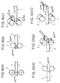
- the leading sheet bar 1 was moved to a point at which the rear end portion of the leading sheet bar 1 trailed 50 mm behind the axis between the centers of the pressing rolls 5 (see Fig. 9(a)). In this position, pressure was applied until the distance between the two pressing rolls 5 became 26 mm. The distance between the pressing rolls 5 became 26 mm by the time the rolling had moved the leading sheet bar 1 by about 25 mm from the start of rolling (see Fig. 9(b)). Rolling was then similarly applied to the rear end portion of the leading sheet bar 1 in the aforesaid manner.
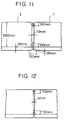
- the leading sheet bar 1 and the trailing sheet bar 2 then moved to the pressing device 6 (Fig. 6), and the pinch rolls 11 and 12 shown in Fig. 6 were used to abut the two sheet bars 1 and 2 against each other. Then, the two sheet bars 1 and 2 were pressed with a force of 3 kgf/mm2 by the pinch rolls 11 and 12 while heating them by using a solenoid coil type induction coil (supplied electric power: 4000 kW, frequency: 500 Hz) shown in Fig. 4. Heating and pressing were stopped when the gap at the center of the bar ends became 5 mm as shown in Fig. 12. Then, hot finish rolling was effected on the sheet bars and a hot-rolled sheet having a thickness of 3 mm was manufactured.
- a solenoid coil type induction coil supplied electric power: 4000 kW, frequency: 500 Hz
- the initial central gap at about 10 mm.
- the gap is desirably selected on the basis of the amount of pressing needed to obtain satisfactory joining. Therefore the gap may vary depending upon the type of the steel, the material and the temperature applied. It is preferable that the gap be substantially about 0.1 times or more the thickness of the sheet bar. According to this embodiment, the thickness reduction work was so performed that the initial gap of about 10 mm could be obtained controlling the gap that remains after the pressing work to about 5 mm in order to obtain a compression of about 5 mm.
- the final gap was beneficial to control the final gap to a value of about 5 mm.
- a predetermined heating temperature cannot always be obtained when heating is performed by the transverse method because, if a contact region is generated in a portion other than the two ends, an induced electric current is generated in the contact region. Therefore, it is preferable to minimize the size of the gap at the central portion realized after the heating and pressing work has been completed, but that the end portions except for the two ends do not contact. From the viewpoint of practical use, it is preferable that the gap be controlled to be about 5 mm in size.
- Finish rolling work was subsequently performed, and a hot-rolled sheet having a thickness of 3 mm was produced.
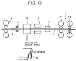
- Fig. 13 of the drawings schematically illustrates a further embodiment of the present invention.
- reference numeral 1 represents a leading sheet bar which has passed through a rough rolling mill
- 2 represents a trailing sheet bar.
- 3 represents a hot finish rolling mill having rolling mill stands F1, F2,..., arranged in a tandem manner
- 4 represents a cutting device for cutting the front and rear end portions of the sheet bars.
- Reference numeral 14 in Fig. 13 represents a working device for upsetting metal in the region of the rear end portion of the cut leading sheet bar 1 and/or the front end portion of the cut trailing sheet bar 2, except for at least the corner portions.
- the upsetting device 14 includes pressing rolls 15 (Fig.
- Reference numeral 6 represents a thermal joining device for thermally joining the upset sheet bars
- 7 represents a scale breaker for removing scale generated on the surface of each of the sheet bars 1 and 2 prior to hot finish rolling.
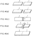
- the rear end portion of the leading sheet bar 1 and the front end portion of the trailing sheet bar 2 are preliminarily cut into the shapes shown in Fig. 14(a). In this configuration no gap is present between the two sheet bars 1 and 2 although the leading sheet bar 1 and the trailing sheet bar 2 are caused to abut against each other. Then, upset work is effected on at least either of the rear end portion of the leading sheet bar 1 or the front end portion of the trailing sheet bar 2 in a region not including the two widthwise directional ends (corners).
- the thicknesses of the upset portions are increased due to the upset work as shown in Fig. 14(b) (according to the Fig. 14(b) embodiment the upset work is effected on both the rear end portion of the leading sheet bar 1 and the front end portion of the trailing sheet bar 2), and a gap is created in the portion, on which the upset work has been effected, when the leading sheet bar and the trailing sheet bar are caused to abut against each other.
- a combination of heating effected by the thermal joining device 6 and pressing performed by adjusting the relative speeds of conveyance of the sheet bars 1 and 2 generates compressive stress in a region adjacent to the two corner portions of the leading sheet bar 1 and the trailing sheet bar 2 as shown in Fig. 14(c) so that the two sheet bars 1 and 2 are brought into contact with each other and joined. Then the joined sheet bars 1 and 2 are sent to the hot finish rolling mill 3 and are subjected to hot finish rolling.
- the regions joined on the inlet side of the hot finish rolling mill 3 are only regions adjacent to the corners of each of the sheet bars 1 and 2 as shown in Fig. 14(c), they can be joined in an extremely short time while having a gap (g).
- the aforesaid gap (g) is formed due to the residual gap created by the upset work performed prior to abutment joining.
- the thickness of the upset portion has been increased due to metal deformation caused by the upset work.
- each of the sheet bars 1 and 2 can be strongly joined over the entire abutting surface as shown in Fig. 14(e). Therefore, even if the material to be rolled is subjected to tension for the purpose of adjusting dimension in finish rolling, the two sheet bars cannot be easily broken or separated from each other.
- each of the cut portions at the ends of the sheet bar may be formed into various shapes such as flat shapes as shown in Fig. 3(a), or combinations of a convex portion and a concave portion as shown in Figs. 3(b) and 3(c).
- cutting means for forming the aforesaid shapes shearing means, gas cutting means or laser fusing means may be employed.
- a device For performing the upset work, a device may be used having the pressing rolls 15 as shown in Fig. 13, or an anvil for the forging work may be employed.
- the widthwise position to which the upset work is applied may be determined to be any portion except at least the two corners of each sheet bar.
- the two sheet bars are caused to abut against each other, and heating and pressing are effected.
- the heating and pressing steps may be performed by any of the following methods:
- the joining allowance W at each of the widthwise spaced ends (corners) be about 0.1 times or more of the sheet bar width B at each end and therefore the total sum of the same may be about 0.2 times or more.
- heating means similar to those employed in the embodiments previously described may be employed.
- a hot-rolling facility arranged as shown in Fig. 13 was used to perform continuous hot-rolling as follows: as the leading and trailing sheet bars, low carbon steel sheet bars having a width of 1000 mm and a thickness of 30 mm were used.
- the rear end portion of the leading sheet bar and the front end portion of the trailing sheet bar were cut so as to be formed into flat shapes as shown in Fig. 14(a).
- Upset work was effected on the central region except for corner portions of 100 mm of each sheet bar in order to create a gap having a size of 10 mm.
- the space bars were caused to abut against each other as shown in Fig. 15. Heating and pressing were performed, narrowing the gap so that a shape as shown in Fig. 16 was formed.
- the heating and pressing conditions were the same as those according to Example 1.
- the leading sheet bar and the trailing sheet bar are partially joined ahead of the hot finish rolls and the end portions of the sheet bars but not the intervening portions are brought into contact with each other and joined as described. Continuous hot-rolling at excellent productivity rates, while eliminating the danger of breakage or separation of the joined portion, is effectively realized.
- Figs. 11 and 12 show joined metal portions at the corners of the abutting edges of the sheet bars, with a gap in between, the bars may be configured to abut at one or more inner portions, with gaps provided at the corners.
- more than one gap portion may be provided, and these may be arranged in various configurations.
- a gap is at a corner or not surrounded by metal, it should preferably be heated by a burner rather than by induction heating.
Landscapes
- Engineering & Computer Science (AREA)
- Mechanical Engineering (AREA)
- Metal Rolling (AREA)
- Pressure Welding/Diffusion-Bonding (AREA)
Applications Claiming Priority (4)
| Application Number | Priority Date | Filing Date | Title |
|---|---|---|---|
| JP3229754A JPH0550112A (ja) | 1991-08-16 | 1991-08-16 | 鋼片の連続熱間圧延方法 |
| JP229754/91 | 1991-08-16 | ||
| JP229755/91 | 1991-08-16 | ||
| JP22975591 | 1991-08-16 |
Publications (2)
| Publication Number | Publication Date |
|---|---|
| EP0528385A1 true EP0528385A1 (de) | 1993-02-24 |
| EP0528385B1 EP0528385B1 (de) | 1996-01-17 |
Family
ID=26528972
Family Applications (1)
| Application Number | Title | Priority Date | Filing Date |
|---|---|---|---|
| EP92113929A Expired - Lifetime EP0528385B1 (de) | 1991-08-16 | 1992-08-14 | Verfahren zum Kontinuierlichen Warmbandwalzen |
Country Status (5)
| Country | Link |
|---|---|
| US (1) | US5217155A (de) |
| EP (1) | EP0528385B1 (de) |
| KR (1) | KR950009139B1 (de) |
| CA (1) | CA2076169C (de) |
| DE (1) | DE69207673T2 (de) |
Cited By (1)
| Publication number | Priority date | Publication date | Assignee | Title |
|---|---|---|---|---|
| WO2000051776A1 (en) * | 1999-03-03 | 2000-09-08 | Evelyn Frances Gray | High speed metal joining process |
Families Citing this family (8)
| Publication number | Priority date | Publication date | Assignee | Title |
|---|---|---|---|---|
| CN1060975C (zh) * | 1993-06-15 | 2001-01-24 | 川崎制铁株式会社 | 金属板的连续热轧方法及在该方法中使用的接合装置 |
| EP0753359B1 (de) * | 1995-07-10 | 2001-06-06 | Kawasaki Steel Corporation | Verfaren und Vorrichtung zum kontinuierlichen Warmbandfertigwalzen |
| US5871137A (en) * | 1996-04-20 | 1999-02-16 | Ege; Sigmund | Automated butt splicer for copper-based tapes |
| US5957369A (en) * | 1996-05-09 | 1999-09-28 | Elpatronic Ag | Method for connecting two workpieces together |
| CA2347427A1 (en) * | 1998-11-18 | 2000-05-25 | Elpatronic Ag | Method and device for laser welding metal sheets |
| US20100212945A1 (en) * | 2006-08-31 | 2010-08-26 | Anthony Faraci | Bond head assembly and system |
| DE102019214295A1 (de) | 2018-11-26 | 2020-05-28 | Sms Group Gmbh | Verfahren zum Verschweißen zweier Brammen |
| DE102021207942A1 (de) * | 2021-07-23 | 2023-01-26 | Sms Group Gmbh | Verfahren und Vorrichtung zum Herstellen eines metallischen Bandes |
Citations (5)
| Publication number | Priority date | Publication date | Assignee | Title |
|---|---|---|---|---|
| EP0201744A2 (de) * | 1985-05-11 | 1986-11-20 | Sms Schloemann-Siemag Aktiengesellschaft | Verfahren zum Walzen von Vorband zu Warmbreitband |
| EP0460655A2 (de) * | 1990-06-06 | 1991-12-11 | Hitachi, Ltd. | Verfahren und Vorrichtung zum Verbinden Aneinanderwalzen erwärmten Materials sowie Verfahren zum kontinuerlichen Warmwalzen und Anordnung |
| EP0490333A2 (de) * | 1990-12-10 | 1992-06-17 | Hitachi, Ltd. | Verfahren und Vorrichtung zum Walzen und Verbinden von Stahlbänder |
| EP0495124A1 (de) * | 1990-08-02 | 1992-07-22 | Kawasaki Steel Corporation | Verfahren zum kontinuierlichen warmwalzen von stahlblech und verfahren zum verbinden desselben |
| EP0495989A1 (de) * | 1990-08-02 | 1992-07-29 | Kawasaki Steel Corporation | Verfahren zum verbinden von knüppeln beim warmwalzen und verfahren zum kontinuierlichen warmwalzen |
Family Cites Families (4)
| Publication number | Priority date | Publication date | Assignee | Title |
|---|---|---|---|---|
| JPS532362A (en) * | 1976-06-30 | 1978-01-11 | Hitachi Ltd | Butt welding |
| JPS5886989A (ja) * | 1981-11-19 | 1983-05-24 | Mitsubishi Heavy Ind Ltd | 拡散溶接による継手溶接法 |
| US4983241A (en) * | 1988-01-28 | 1991-01-08 | Fuji Photo Film Co., Ltd. | Method of splicing webs |
| DE68927840T2 (de) * | 1988-08-11 | 1997-06-19 | Fuji Photo Film Co Ltd | Verfahren zum Verbinden von Metallbändern |
-
1992
- 1992-08-10 US US07/927,599 patent/US5217155A/en not_active Expired - Fee Related
- 1992-08-14 EP EP92113929A patent/EP0528385B1/de not_active Expired - Lifetime
- 1992-08-14 CA CA002076169A patent/CA2076169C/en not_active Expired - Fee Related
- 1992-08-14 DE DE69207673T patent/DE69207673T2/de not_active Expired - Fee Related
- 1992-08-17 KR KR1019920014799A patent/KR950009139B1/ko not_active Expired - Fee Related
Patent Citations (5)
| Publication number | Priority date | Publication date | Assignee | Title |
|---|---|---|---|---|
| EP0201744A2 (de) * | 1985-05-11 | 1986-11-20 | Sms Schloemann-Siemag Aktiengesellschaft | Verfahren zum Walzen von Vorband zu Warmbreitband |
| EP0460655A2 (de) * | 1990-06-06 | 1991-12-11 | Hitachi, Ltd. | Verfahren und Vorrichtung zum Verbinden Aneinanderwalzen erwärmten Materials sowie Verfahren zum kontinuerlichen Warmwalzen und Anordnung |
| EP0495124A1 (de) * | 1990-08-02 | 1992-07-22 | Kawasaki Steel Corporation | Verfahren zum kontinuierlichen warmwalzen von stahlblech und verfahren zum verbinden desselben |
| EP0495989A1 (de) * | 1990-08-02 | 1992-07-29 | Kawasaki Steel Corporation | Verfahren zum verbinden von knüppeln beim warmwalzen und verfahren zum kontinuierlichen warmwalzen |
| EP0490333A2 (de) * | 1990-12-10 | 1992-06-17 | Hitachi, Ltd. | Verfahren und Vorrichtung zum Walzen und Verbinden von Stahlbänder |
Non-Patent Citations (3)
| Title |
|---|
| PATENT ABSTRACTS OF JAPAN vol. 7, no. 50 (M-197)(1195) 26 February 1983 & JP-A-57 199 502 ( SUMITOMO KINZOKU KOGYO ) 7 December 1982 * |
| PATENT ABSTRACTS OF JAPAN vol. 8, no. 258 (M-340)(1695) 27 November 1984 & JP-A-59 130 603 ( SUMITOMO KINZOKU KOGYO ) 27 July 1984 * |
| PATENT ABSTRACTS OF JAPAN vol. 8, no. 270 (M-344)(1707) 11 December 1984 & JP-A-59 141 301 ( SUMITOMO KINZOKU KOGYO ) 14 August 1984 * |
Cited By (1)
| Publication number | Priority date | Publication date | Assignee | Title |
|---|---|---|---|---|
| WO2000051776A1 (en) * | 1999-03-03 | 2000-09-08 | Evelyn Frances Gray | High speed metal joining process |
Also Published As
| Publication number | Publication date |
|---|---|
| DE69207673T2 (de) | 1996-05-30 |
| CA2076169A1 (en) | 1993-02-17 |
| DE69207673D1 (de) | 1996-02-29 |
| KR950009139B1 (ko) | 1995-08-16 |
| EP0528385B1 (de) | 1996-01-17 |
| KR930003979A (ko) | 1993-03-22 |
| CA2076169C (en) | 1995-09-05 |
| US5217155A (en) | 1993-06-08 |
Similar Documents
| Publication | Publication Date | Title |
|---|---|---|
| EP0753359B1 (de) | Verfaren und Vorrichtung zum kontinuierlichen Warmbandfertigwalzen | |
| EP0495989B1 (de) | Verfahren zum verbinden von knüppeln beim warmwalzen und verfahren zum kontinuierlichen warmwalzen | |
| CN102019325B (zh) | 热轧带钢无头轧制中间坯的连接方法 | |
| CN104815907A (zh) | 一种热轧带钢中间坯的快速连接模具及方法 | |
| US5217155A (en) | Method of continuously hot-rolling sheet bars | |
| JPH0623406A (ja) | 鋼片の連続熱間圧延方法 | |
| JPS59141303A (ja) | 連続式熱間圧延方法 | |
| KR100983358B1 (ko) | 연연속 열간 압연설비 | |
| JPH08294703A (ja) | 熱間圧延における鋼片の接合方法 | |
| JP2905347B2 (ja) | 熱間圧延における鋼片の接合方法 | |
| JP3283388B2 (ja) | 鋼片の接合方法 | |
| JPH06238303A (ja) | 鋼片の連続熱間圧延方法 | |
| JP3105709B2 (ja) | 連続熱間圧延における鋼片の接合方法 | |
| JP2938689B2 (ja) | 熱間圧延における鋼片の接合方法 | |
| JP2975147B2 (ja) | 熱間圧延における鋼片の接合方法 | |
| JPH04288906A (ja) | 鋼片の連続熱間圧延方法 | |
| JPH0716687B2 (ja) | 熱間圧延における鋼片の接合方法 | |
| JP2905392B2 (ja) | 鋼片の接合方法 | |
| JPH08141602A (ja) | 熱間圧延における鋼片の接合方法 | |
| JPH0716685B2 (ja) | 熱間圧延における鋼片の接合方法 | |
| JP2971711B2 (ja) | 連続熱間圧延における鋼片の接合方法 | |
| JPH0569008A (ja) | 鋼片の連続熱間圧延方法 | |
| AU710706B2 (en) | Method and apparatus for continuous finishing hot-rolling a steel strip | |
| JPH0871607A (ja) | 鋼片の連続熱間圧延方法 | |
| JP2875054B2 (ja) | 熱間圧延における鋼片の接合方法 |
Legal Events
| Date | Code | Title | Description |
|---|---|---|---|
| PUAI | Public reference made under article 153(3) epc to a published international application that has entered the european phase |
Free format text: ORIGINAL CODE: 0009012 |
|
| AK | Designated contracting states |
Kind code of ref document: A1 Designated state(s): DE FR GB IT |
|
| 17P | Request for examination filed |
Effective date: 19930609 |
|
| 17Q | First examination report despatched |
Effective date: 19940316 |
|
| GRAA | (expected) grant |
Free format text: ORIGINAL CODE: 0009210 |
|
| AK | Designated contracting states |
Kind code of ref document: B1 Designated state(s): DE FR GB IT |
|
| REF | Corresponds to: |
Ref document number: 69207673 Country of ref document: DE Date of ref document: 19960229 |
|
| ET | Fr: translation filed | ||
| ITF | It: translation for a ep patent filed | ||
| PLBE | No opposition filed within time limit |
Free format text: ORIGINAL CODE: 0009261 |
|
| 26N | No opposition filed | ||
| PGFP | Annual fee paid to national office [announced via postgrant information from national office to epo] |
Ref country code: DE Payment date: 20000807 Year of fee payment: 9 |
|
| PGFP | Annual fee paid to national office [announced via postgrant information from national office to epo] |
Ref country code: GB Payment date: 20000809 Year of fee payment: 9 |
|
| PGFP | Annual fee paid to national office [announced via postgrant information from national office to epo] |
Ref country code: FR Payment date: 20000811 Year of fee payment: 9 |
|
| PG25 | Lapsed in a contracting state [announced via postgrant information from national office to epo] |
Ref country code: GB Free format text: LAPSE BECAUSE OF NON-PAYMENT OF DUE FEES Effective date: 20010814 |
|
| GBPC | Gb: european patent ceased through non-payment of renewal fee |
Effective date: 20010814 |
|
| PG25 | Lapsed in a contracting state [announced via postgrant information from national office to epo] |
Ref country code: FR Free format text: LAPSE BECAUSE OF NON-PAYMENT OF DUE FEES Effective date: 20020430 |
|
| PG25 | Lapsed in a contracting state [announced via postgrant information from national office to epo] |
Ref country code: DE Free format text: LAPSE BECAUSE OF NON-PAYMENT OF DUE FEES Effective date: 20020501 |
|
| REG | Reference to a national code |
Ref country code: FR Ref legal event code: ST |
|
| PG25 | Lapsed in a contracting state [announced via postgrant information from national office to epo] |
Ref country code: IT Free format text: LAPSE BECAUSE OF NON-PAYMENT OF DUE FEES Effective date: 20050814 |