EP0529280A2 - Installation de réglage de la pression de freinage dans un véhicule automobile - Google Patents
Installation de réglage de la pression de freinage dans un véhicule automobile Download PDFInfo
- Publication number
- EP0529280A2 EP0529280A2 EP92112219A EP92112219A EP0529280A2 EP 0529280 A2 EP0529280 A2 EP 0529280A2 EP 92112219 A EP92112219 A EP 92112219A EP 92112219 A EP92112219 A EP 92112219A EP 0529280 A2 EP0529280 A2 EP 0529280A2
- Authority
- EP
- European Patent Office
- Prior art keywords
- brake pressure
- wheel
- brake
- rear axle
- slip
- Prior art date
- Legal status (The legal status is an assumption and is not a legal conclusion. Google has not performed a legal analysis and makes no representation as to the accuracy of the status listed.)
- Granted
Links
Images

Classifications
-
- B—PERFORMING OPERATIONS; TRANSPORTING
- B60—VEHICLES IN GENERAL
- B60T—VEHICLE BRAKE CONTROL SYSTEMS OR PARTS THEREOF; BRAKE CONTROL SYSTEMS OR PARTS THEREOF, IN GENERAL; ARRANGEMENT OF BRAKING ELEMENTS ON VEHICLES IN GENERAL; PORTABLE DEVICES FOR PREVENTING UNWANTED MOVEMENT OF VEHICLES; VEHICLE MODIFICATIONS TO FACILITATE COOLING OF BRAKES
- B60T8/00—Arrangements for adjusting wheel-braking force to meet varying vehicular or ground-surface conditions, e.g. limiting or varying distribution of braking force
- B60T8/17—Using electrical or electronic regulation means to control braking
- B60T8/1755—Brake regulation specially adapted to control the stability of the vehicle, e.g. taking into account yaw rate or transverse acceleration in a curve
-
- B—PERFORMING OPERATIONS; TRANSPORTING
- B60—VEHICLES IN GENERAL
- B60T—VEHICLE BRAKE CONTROL SYSTEMS OR PARTS THEREOF; BRAKE CONTROL SYSTEMS OR PARTS THEREOF, IN GENERAL; ARRANGEMENT OF BRAKING ELEMENTS ON VEHICLES IN GENERAL; PORTABLE DEVICES FOR PREVENTING UNWANTED MOVEMENT OF VEHICLES; VEHICLE MODIFICATIONS TO FACILITATE COOLING OF BRAKES
- B60T2230/00—Monitoring, detecting special vehicle behaviour; Counteracting thereof
- B60T2230/02—Side slip angle, attitude angle, floating angle, drift angle
Definitions
- the braking force distribution of a conventional vehicle relates to the relationship between the front and rear axle braking force.
- This ratio cannot be influenced by the driver, since he brakes both axles with a brake pedal, so that the brake force distribution must be determined in a targeted manner when designing the vehicle brakes.
- the goal of an ideal braking force distribution is on the one hand to brake the front and rear axles equally (based on the dynamic axle loads), and on the other hand to choose the distribution when cornering so that a neutral driving behavior is achieved.
- the goal of neutral driving behavior is superior to the goal of equal braking.
- the same level of braking (based on the dynamic axle loads) at the front and rear can be achieved when driving straight ahead.
- cornering especially in the corner limit area
- the braking of the rear axle must be chosen lower than on the front axle in favor of driving behavior.
- the brake force distribution is selected in accordance with the legal regulations so that the rear axle does not come to a block in front of the front axle. This requirement is due to the fact that if the rear axle is braked too hard, the vehicle can become unstable when braking on a curve, i.e. it can cause skidding.
- limiters or reducers are certainly necessary for some vehicles, but they basically worsen the stability when cornering (in comparison to conventional fixed tuning, i.e. to the straight line not bent).
- the rear axle pressure is regulated so that the slowest rear wheel runs slightly slower than the fastest front wheel. This ensures high rear axle braking when driving straight ahead.
- the control system brakes the rear axle less than the front axle due to the circular kinematics and the wheel load shifting (left - right). Wheel speed sensors and pressure sensors are required for the pressure on the rear and front axles.
- the invention achieves that there is no under-braked rear axle when braking on bends (tight bends below curve limit speed) due to the circular geometry, that tire tolerances have no effect and that the setpoint of the stability controller is not specified in a controlled manner, but in the sense of a neutral driving behavior is determined by the front wheels.
- the available pressure information and the corresponding wheel reactions are used to derive important state variables such as wheel forces (F_br, F_nor) or brake slips ⁇ .
- the solution according to the invention provides a closed solution for regulating the same slip angle on the front and rear axles and thus for neutral vehicle behavior; this applies to every driving situation, including tight bends.
- Neutral braking behavior is characterized by roughly the same slip angle on the front and rear axles.
- the skew is an ideal control variable.
- the slope of the adhesion coefficient / slip curve in the linear range is now a measure of the slip angle and is therefore used as a control variable for stability control.
- the quantities F_Br, F_N and ⁇ required to determine the gradient m are estimated from the existing wheel pressures and wheel speeds V Ri as follows:
- the braking forces F_Br are determined from the front axle pressure pva, the rear axle pressure pha and brake parameters:
- the deceleration of the fastest front wheel is determined using a line filter; an optimal straight line (in the sense of minimizing the distance squares between speed values and straight line points) is placed over n points of the wheel speed and its slope V R is determined.
- a_1 V ⁇ R / (1- ⁇ R ) Since the wheel slip ⁇ R is in good approximation directly proportional to the applied wheel pressure (independent of u!)
- limit values for the reference deceleration are calculated from the calculated braking forces for the largest and smallest possible FC mass: with ⁇ : correction value due to safety (e.g. braking on a mountain)
- the past reference speed is extrapolated with the previously determined slope a 1 and thus a new current reference value is established.
- references support each other:
- the rule applies that in principle the reference that cannot be corrected so far downwards or upwards is more reliable. Accordingly, this reference is set to the expected value v_ref er .
- the reference correction of the other FZ side is supported by a PT1 filter by correcting the more reliable reference. This prevents a strongly slipping front wheel from pulling the corresponding reference.
- the curve radius kr can be estimated from the wheel speeds and the track width:
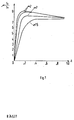
- the ⁇ - ⁇ curves show linear behavior for the partial braking range under consideration.
- This type of evaluation has the particular advantage that the control described works independently of any tire tolerances.
- Fig. 1 of the drawing shows that the ⁇ -slip curves are dependent on the slip angle ⁇ .
- FIG. 2 An exemplary embodiment of the invention is explained with reference to FIG. 2 using a control principle shown as a block diagram.
- the driver specifies the front axle brake pressure pva, which acts on the front axle brakes 2.
- the braking torque M b generated thereby acts on the block 3, which should contain the front wheels, the tires and the road.
- the axle pressures are regulated to the same slip angle.
- the axle pressures pva and pha and the wheel speeds V Ri are fed to a block 12.
- the current gradients mv and mh of the valid ⁇ slip curves on the two axes are determined in accordance with the relationships 1 to 8 listed above.
- the slope mv of the front axle goes as a setpoint to a comparator 13, to which the slope mh is also fed.
- the difference between the m values is converted in a stability controller 14, which essentially has a proportional-differential transmission behavior, into a setpoint signal psoll-corr for the rear axle brake pressure, to which a pressure controller 6 adjusts. Dier generates a control signal UK for a solenoid valve 7 to which a pressure source, not shown, is connected. At the outlet of the valve 7 and in the rear axle brakes 8, a rear axle brake pressure is adjusted on a line 9 to a comparator 10 due to the return of a signal corresponding to this brake pressure, which corresponds to the predetermined target brake pressure.
- the braking torque generated influences the speeds vhl, vhr of the rear wheels via a block 11 (rear wheels, tires, road).
- An upper limit value psha for the rear axle brake pressure is determined from the front axle brake pressure pva in accordance with the ideal brake force distribution for fully loaded vehicle 5.
- switch 4 switches to the position not shown.
- the control principle shown in FIG. 2 applies to one side of the vehicle.
- the pressure regulator according to the invention can have an ABS and / or an ASR arranged next to it.
Landscapes
- Engineering & Computer Science (AREA)
- Transportation (AREA)
- Mechanical Engineering (AREA)
- Regulating Braking Force (AREA)
Applications Claiming Priority (2)
| Application Number | Priority Date | Filing Date | Title |
|---|---|---|---|
| DE4128087A DE4128087A1 (de) | 1991-08-24 | 1991-08-24 | Bremsdruckregelanlage fuer ein fahrzeug |
| DE4128087 | 1991-08-24 |
Publications (3)
| Publication Number | Publication Date |
|---|---|
| EP0529280A2 true EP0529280A2 (fr) | 1993-03-03 |
| EP0529280A3 EP0529280A3 (en) | 1993-05-19 |
| EP0529280B1 EP0529280B1 (fr) | 1996-05-01 |
Family
ID=6439020
Family Applications (1)
| Application Number | Title | Priority Date | Filing Date |
|---|---|---|---|
| EP92112219A Expired - Lifetime EP0529280B1 (fr) | 1991-08-24 | 1992-07-17 | Installation de réglage de la pression de freinage dans un véhicule automobile |
Country Status (4)
| Country | Link |
|---|---|
| EP (1) | EP0529280B1 (fr) |
| JP (1) | JPH06166367A (fr) |
| DE (2) | DE4128087A1 (fr) |
| HU (1) | HUT69196A (fr) |
Cited By (9)
| Publication number | Priority date | Publication date | Assignee | Title |
|---|---|---|---|---|
| EP0767094A1 (fr) * | 1995-10-06 | 1997-04-09 | Toyota Jidosha Kabushiki Kaisha | Dispositif de contrÔle du comportement des véhicules basé sur la surveillance du mouvement des roues arrières |
| FR2771366A1 (fr) * | 1997-11-27 | 1999-05-28 | Honda Motor Co Ltd | Procede et dispositif de calcul d'angle de derapage de caisse dans un systeme de controle de mouvement de vehicule |
| WO2000047458A1 (fr) * | 1999-02-11 | 2000-08-17 | Continental Teves Ag & Co. Ohg | Procede et dispositif permettant de determiner la force de freinage appliquee a la surface de contact d'une roue de vehicule |
| EP0979763A3 (fr) * | 1998-08-08 | 2000-09-27 | Volkswagen Aktiengesellschaft | Méthode de détermination du rayon de courbure |
| WO2001070549A1 (fr) * | 2000-03-22 | 2001-09-27 | Robert Bosch Gmbh | Procede pour determiner l'acceleration transversale d'un vehicule automobile |
| WO2002053433A1 (fr) * | 2000-12-30 | 2002-07-11 | Robert Bosch Gmbh | Systeme et procede de commande et/ou de regulation du comportement de conduite d'un vehicule automobile |
| FR2853609A1 (fr) * | 2003-04-09 | 2004-10-15 | Bosch Gmbh Robert | Procede et dispositif de reduction de la charge de freinage sur au moins un frein de roue |
| DE19954198B4 (de) * | 1999-02-11 | 2011-08-18 | Continental Teves AG & Co. OHG, 60488 | Verfahren und Vorrichtung zur Ermittlung einer in der Aufstandsfläche eines Rades eines Fahrzeugs wirkenden Bremskraft |
| CN106476799A (zh) * | 2015-08-27 | 2017-03-08 | 富士重工业株式会社 | 车辆控制装置及车辆控制方法 |
Families Citing this family (13)
| Publication number | Priority date | Publication date | Assignee | Title |
|---|---|---|---|---|
| DE4243668C2 (de) * | 1992-12-23 | 2003-01-23 | Bosch Gmbh Robert | Bremsanlage für ein Kraftfahrzeug |
| DE4417935A1 (de) * | 1994-05-21 | 1995-11-23 | Teves Gmbh Alfred | Schaltungsanordnung für eine Bremsanlage mit elektronischer Regelung der Bremskraftverteilung |
| DE19515050A1 (de) * | 1994-11-25 | 1996-05-30 | Teves Gmbh Alfred | Verfahren zur Fahrstabilitätsregelschaltung mit Steuerung über Druckgradienten |
| US5941608A (en) | 1996-03-07 | 1999-08-24 | Kelsey-Hayes Company | Electronic brake management system with manual fail safe |
| DE19617590A1 (de) * | 1996-05-02 | 1997-11-06 | Teves Gmbh Alfred | Verfahren zur Bestimmung eines Fahrzeug-Sollverhaltens |
| JP3826524B2 (ja) | 1997-11-26 | 2006-09-27 | アイシン精機株式会社 | 車両の制動制御装置 |
| DE19955094A1 (de) * | 1999-11-16 | 2001-05-23 | Siemens Ag | Verfahren zur Bremsregelung eines Kraftfahrzeugs und Bremsvorrichtung für ein Kraftfahrzeug |
| DE10141548B4 (de) * | 2001-01-05 | 2013-01-17 | Continental Teves Ag & Co. Ohg | Verfahren zur Regelung des Motorschleppmomentes in Personenkraftfahrzeugen |
| US6860569B1 (en) | 2002-05-23 | 2005-03-01 | Kelsey-Hayes Company | Electro-hydraulic brake system with four wheel push through |
| DE102004053880A1 (de) * | 2004-11-04 | 2006-05-11 | Daimlerchrysler Ag | Verfahren zur Bestimmung des maximalen Reibwertes zwischen Fahrzeugreifen und Fahrbahnoberfläche |
| DE102008002345A1 (de) | 2008-06-11 | 2009-12-17 | Robert Bosch Gmbh | Bremseinrichtung für ein Kraftfahrzeug mit wenigstens drei Bremskreisen |
| DE102008041760A1 (de) | 2008-06-11 | 2009-12-17 | Robert Bosch Gmbh | Bremseinrichtung für ein Kraftfahrzeug |
| DE102008002348A1 (de) | 2008-06-11 | 2009-12-17 | Robert Bosch Gmbh | Bremseinrichtung für ein Kraftfahrzeug mit einem Druckspeicher |
Family Cites Families (15)
| Publication number | Priority date | Publication date | Assignee | Title |
|---|---|---|---|---|
| DE3301948A1 (de) * | 1983-01-21 | 1984-07-26 | Alfred Teves Gmbh, 6000 Frankfurt | Verfahren und vorrichtung zur steuerung der bremskraftverteilung |
| DE3306611A1 (de) * | 1983-02-25 | 1984-08-30 | Alfred Teves Gmbh, 6000 Frankfurt | Verfahren und vorrichtung zur steuerung der bremskraftverteilung |
| JPH0613287B2 (ja) * | 1984-05-21 | 1994-02-23 | 日産自動車株式会社 | 車両用制動力制御装置 |
| DE3432841A1 (de) * | 1984-09-07 | 1986-03-20 | Robert Bosch Gmbh, 7000 Stuttgart | Bremskraftregelanlage |
| DE3535843A1 (de) * | 1985-10-08 | 1987-04-16 | Bosch Gmbh Robert | Verfahren zur fortlaufenden bestimmung des kraftschlussbeiwerts (my) |
| DE3731756A1 (de) * | 1987-09-22 | 1989-03-30 | Bosch Gmbh Robert | Verfahren zur regelung der fahrstabilitaet eines fahrzeugs |
| DE3817546A1 (de) * | 1988-05-24 | 1989-12-07 | Bosch Gmbh Robert | Verfahren zur erhoehung der beherrschbarkeit eines gebremsten fahrzeuges |
| DE3833211C2 (de) * | 1988-09-30 | 1996-07-25 | Bosch Gmbh Robert | Verfahren zur fortlaufenden Bestimmung des Kraftschlußbeiwerts mu |
| DE3840456A1 (de) * | 1988-12-01 | 1990-06-07 | Bosch Gmbh Robert | Verfahren zur erhoehung der beherrschbarkeit eines fahrzeugs |
| DE3912014C2 (de) * | 1989-04-12 | 1998-07-09 | Bayerische Motoren Werke Ag | Verfahren zur Ermittlung des Reibwertes zwischen der Fahrbahn und den Reifen eines Fahrzeuges |
| DE3934307C3 (de) * | 1989-10-13 | 1998-10-01 | Lucas Ind Plc | Verfahren zum Steuern des Bremsdruckes in einer blockiergeschützten Bremsanlage |
| DE3935588A1 (de) * | 1989-10-23 | 1991-04-25 | Forschungsgesellschaft Kraftfa | Verfahren zur gewaehrleistung der fahrstabilitaet von kraftfahrzeugen |
| DE3941409C1 (en) * | 1989-12-15 | 1991-04-18 | Mercedes-Benz Aktiengesellschaft, 7000 Stuttgart, De | Hydraulic dual circuit brake installation for motor vehicle - has electronic control stage for pressure modulator with drive pressure chamber for automatic braking force distribution approaching ideal |
| DE4026626A1 (de) * | 1990-08-23 | 1992-02-27 | Bosch Gmbh Robert | Verfahren zur regelung der fahrzeugdynamik |
| DE4026627A1 (de) * | 1990-08-23 | 1992-02-27 | Bosch Gmbh Robert | Fahrzeug |
-
1991
- 1991-08-24 DE DE4128087A patent/DE4128087A1/de not_active Withdrawn
-
1992
- 1992-07-17 EP EP92112219A patent/EP0529280B1/fr not_active Expired - Lifetime
- 1992-07-17 DE DE59206162T patent/DE59206162D1/de not_active Expired - Fee Related
- 1992-08-07 JP JP4211453A patent/JPH06166367A/ja active Pending
- 1992-08-19 HU HU9202713A patent/HUT69196A/hu unknown
Cited By (13)
| Publication number | Priority date | Publication date | Assignee | Title |
|---|---|---|---|---|
| EP0767094A1 (fr) * | 1995-10-06 | 1997-04-09 | Toyota Jidosha Kabushiki Kaisha | Dispositif de contrÔle du comportement des véhicules basé sur la surveillance du mouvement des roues arrières |
| FR2771366A1 (fr) * | 1997-11-27 | 1999-05-28 | Honda Motor Co Ltd | Procede et dispositif de calcul d'angle de derapage de caisse dans un systeme de controle de mouvement de vehicule |
| EP0979763A3 (fr) * | 1998-08-08 | 2000-09-27 | Volkswagen Aktiengesellschaft | Méthode de détermination du rayon de courbure |
| WO2000047458A1 (fr) * | 1999-02-11 | 2000-08-17 | Continental Teves Ag & Co. Ohg | Procede et dispositif permettant de determiner la force de freinage appliquee a la surface de contact d'une roue de vehicule |
| DE19954198B4 (de) * | 1999-02-11 | 2011-08-18 | Continental Teves AG & Co. OHG, 60488 | Verfahren und Vorrichtung zur Ermittlung einer in der Aufstandsfläche eines Rades eines Fahrzeugs wirkenden Bremskraft |
| US6584396B2 (en) | 2000-03-22 | 2003-06-24 | Robert Bosch Gmbh | Method for determining the lateral acceleration of a motor vehicle |
| WO2001070549A1 (fr) * | 2000-03-22 | 2001-09-27 | Robert Bosch Gmbh | Procede pour determiner l'acceleration transversale d'un vehicule automobile |
| WO2002053433A1 (fr) * | 2000-12-30 | 2002-07-11 | Robert Bosch Gmbh | Systeme et procede de commande et/ou de regulation du comportement de conduite d'un vehicule automobile |
| US6810317B2 (en) | 2000-12-30 | 2004-10-26 | Robert Bosch Gmbh | System and method for controlling and/or regulating the handling characteristics of a motor vehicle |
| FR2853609A1 (fr) * | 2003-04-09 | 2004-10-15 | Bosch Gmbh Robert | Procede et dispositif de reduction de la charge de freinage sur au moins un frein de roue |
| CN100340437C (zh) * | 2003-04-09 | 2007-10-03 | 罗伯特—博希股份公司 | 降低在至少一个轮闸上的制动载荷的方法和设备 |
| CN106476799A (zh) * | 2015-08-27 | 2017-03-08 | 富士重工业株式会社 | 车辆控制装置及车辆控制方法 |
| CN106476799B (zh) * | 2015-08-27 | 2018-01-30 | 株式会社斯巴鲁 | 车辆控制装置及车辆控制方法 |
Also Published As
| Publication number | Publication date |
|---|---|
| JPH06166367A (ja) | 1994-06-14 |
| HUT69196A (en) | 1995-08-28 |
| DE4128087A1 (de) | 1993-02-25 |
| EP0529280A3 (en) | 1993-05-19 |
| EP0529280B1 (fr) | 1996-05-01 |
| DE59206162D1 (de) | 1996-06-05 |
Similar Documents
| Publication | Publication Date | Title |
|---|---|---|
| EP0529280B1 (fr) | Installation de réglage de la pression de freinage dans un véhicule automobile | |
| EP0051801B1 (fr) | Installation d'antiblocage | |
| EP0445575B1 (fr) | Procédé de répartition de pression de freinage entre les axes d'un véhicule automobile muni d'un frein à fluide sous pression à anti-blocage | |
| DE60022737T2 (de) | Vorrichung und Verfahren zur Bestimmung von Fahrzeugbetriebs-und Dynamikparametern | |
| EP0509237B1 (fr) | Système régulateur de pression des freins d'un véhicule | |
| DE69111704T2 (de) | Bremsdrucksteuerungsverfahren und Anlage. | |
| DE4010332C2 (fr) | ||
| DE69504783T2 (de) | Vorrichtung zum Steuern des Kurvenverhaltens eines Fahrzeuges | |
| EP1030797B1 (fr) | Procede et dispositif pour stabiliser un vehicule en fonction de la grandeur de sa vitesse | |
| EP1351843B1 (fr) | Dispositif et procede de fonctionnement d'un vehicule | |
| DE69031050T2 (de) | Bremssteuereinrichtung in einem Blockierschutz-Bremssystem | |
| EP1047585A1 (fr) | Procede et dispositif destines a stabiliser un vehicule, plus precisement a l'empecher de culbuter | |
| DE3518221A1 (de) | Ausbrechempfindliches bremssteuerungssystem fuer kraftfahrzeuge | |
| DE102015015922A1 (de) | Verfahren zum Einstellen von Bremsdrücken an pneumatisch betätigten Radbremsen eines Fahrzeugs, Bremsanlage zur Durchführung des Verfahrens sowie Fahrzeug | |
| DE112011103701B4 (de) | Bremskraft-Steuervorrichtung | |
| EP0572808B1 (fr) | Système de régulation antiblocage | |
| DE19624491C2 (de) | Vorrichtung zum Steuern der Bremskraftverteilung eines Fahrzeugs | |
| DE3201047C2 (fr) | ||
| EP2049372B1 (fr) | Procédé de distribution de la pression de freinage aux essieux d'un véhicule | |
| DE102015006738A1 (de) | Verfahren und Vorrichtung zum elektronischen Regeln einer Fahrzeugverzögerung in einem ABS-Bremssystem | |
| DE102015006737A1 (de) | Verfahren und Vorrichtung zum elektronischen Regeln einer Fahrzeugverzögerung in einem ABS-Bremssystem | |
| EP0555812A2 (fr) | Système de régulation antiblocage pour motor | |
| EP2590845B1 (fr) | Procédé de détermination d'une vitesse de référence de véhicule et système de freinage | |
| DE102011017018B3 (de) | Verfahren zur Lastabhängigen Bremsdruckregelung | |
| DE69201791T2 (de) | Bremsen mit verzögerungssteuerung. |
Legal Events
| Date | Code | Title | Description |
|---|---|---|---|
| PUAI | Public reference made under article 153(3) epc to a published international application that has entered the european phase |
Free format text: ORIGINAL CODE: 0009012 |
|
| AK | Designated contracting states |
Kind code of ref document: A2 Designated state(s): DE FR GB SE |
|
| PUAL | Search report despatched |
Free format text: ORIGINAL CODE: 0009013 |
|
| AK | Designated contracting states |
Kind code of ref document: A3 Designated state(s): DE FR GB SE |
|
| 17P | Request for examination filed |
Effective date: 19931102 |
|
| 17Q | First examination report despatched |
Effective date: 19950116 |
|
| GRAH | Despatch of communication of intention to grant a patent |
Free format text: ORIGINAL CODE: EPIDOS IGRA |
|
| GRAA | (expected) grant |
Free format text: ORIGINAL CODE: 0009210 |
|
| AK | Designated contracting states |
Kind code of ref document: B1 Designated state(s): DE FR GB SE |
|
| ET | Fr: translation filed | ||
| REF | Corresponds to: |
Ref document number: 59206162 Country of ref document: DE Date of ref document: 19960605 |
|
| GBT | Gb: translation of ep patent filed (gb section 77(6)(a)/1977) |
Effective date: 19960603 |
|
| PG25 | Lapsed in a contracting state [announced via postgrant information from national office to epo] |
Ref country code: SE Effective date: 19960801 |
|
| PLBE | No opposition filed within time limit |
Free format text: ORIGINAL CODE: 0009261 |
|
| STAA | Information on the status of an ep patent application or granted ep patent |
Free format text: STATUS: NO OPPOSITION FILED WITHIN TIME LIMIT |
|
| 26N | No opposition filed | ||
| PGFP | Annual fee paid to national office [announced via postgrant information from national office to epo] |
Ref country code: GB Payment date: 19980703 Year of fee payment: 7 |
|
| PGFP | Annual fee paid to national office [announced via postgrant information from national office to epo] |
Ref country code: FR Payment date: 19980720 Year of fee payment: 7 |
|
| PG25 | Lapsed in a contracting state [announced via postgrant information from national office to epo] |
Ref country code: GB Free format text: LAPSE BECAUSE OF NON-PAYMENT OF DUE FEES Effective date: 19990717 |
|
| PG25 | Lapsed in a contracting state [announced via postgrant information from national office to epo] |
Ref country code: FR Free format text: THE PATENT HAS BEEN ANNULLED BY A DECISION OF A NATIONAL AUTHORITY Effective date: 19990731 |
|
| GBPC | Gb: european patent ceased through non-payment of renewal fee |
Effective date: 19990717 |
|
| REG | Reference to a national code |
Ref country code: FR Ref legal event code: ST |
|
| PGFP | Annual fee paid to national office [announced via postgrant information from national office to epo] |
Ref country code: DE Payment date: 20050916 Year of fee payment: 14 |
|
| PG25 | Lapsed in a contracting state [announced via postgrant information from national office to epo] |
Ref country code: DE Free format text: LAPSE BECAUSE OF NON-PAYMENT OF DUE FEES Effective date: 20070201 |