EP0051801B1 - Installation d'antiblocage - Google Patents
Installation d'antiblocage Download PDFInfo
- Publication number
- EP0051801B1 EP0051801B1 EP81109096A EP81109096A EP0051801B1 EP 0051801 B1 EP0051801 B1 EP 0051801B1 EP 81109096 A EP81109096 A EP 81109096A EP 81109096 A EP81109096 A EP 81109096A EP 0051801 B1 EP0051801 B1 EP 0051801B1
- Authority
- EP
- European Patent Office
- Prior art keywords
- wheel
- wheels
- select
- decelerated
- braking
- Prior art date
- Legal status (The legal status is an assumption and is not a legal conclusion. Google has not performed a legal analysis and makes no representation as to the accuracy of the status listed.)
- Expired
Links
Images
Classifications
-
- B—PERFORMING OPERATIONS; TRANSPORTING
- B60—VEHICLES IN GENERAL
- B60T—VEHICLE BRAKE CONTROL SYSTEMS OR PARTS THEREOF; BRAKE CONTROL SYSTEMS OR PARTS THEREOF, IN GENERAL; ARRANGEMENT OF BRAKING ELEMENTS ON VEHICLES IN GENERAL; PORTABLE DEVICES FOR PREVENTING UNWANTED MOVEMENT OF VEHICLES; VEHICLE MODIFICATIONS TO FACILITATE COOLING OF BRAKES
- B60T8/00—Arrangements for adjusting wheel-braking force to meet varying vehicular or ground-surface conditions, e.g. limiting or varying distribution of braking force
- B60T8/32—Arrangements for adjusting wheel-braking force to meet varying vehicular or ground-surface conditions, e.g. limiting or varying distribution of braking force responsive to a speed condition, e.g. acceleration or deceleration
- B60T8/34—Arrangements for adjusting wheel-braking force to meet varying vehicular or ground-surface conditions, e.g. limiting or varying distribution of braking force responsive to a speed condition, e.g. acceleration or deceleration having a fluid pressure regulator responsive to a speed condition
- B60T8/343—Systems characterised by their lay-out
- B60T8/344—Hydraulic systems
- B60T8/346—2 Channel systems
-
- B—PERFORMING OPERATIONS; TRANSPORTING
- B60—VEHICLES IN GENERAL
- B60T—VEHICLE BRAKE CONTROL SYSTEMS OR PARTS THEREOF; BRAKE CONTROL SYSTEMS OR PARTS THEREOF, IN GENERAL; ARRANGEMENT OF BRAKING ELEMENTS ON VEHICLES IN GENERAL; PORTABLE DEVICES FOR PREVENTING UNWANTED MOVEMENT OF VEHICLES; VEHICLE MODIFICATIONS TO FACILITATE COOLING OF BRAKES
- B60T8/00—Arrangements for adjusting wheel-braking force to meet varying vehicular or ground-surface conditions, e.g. limiting or varying distribution of braking force
- B60T8/17—Using electrical or electronic regulation means to control braking
- B60T8/176—Brake regulation specially adapted to prevent excessive wheel slip during vehicle deceleration, e.g. ABS
- B60T8/1764—Regulation during travel on surface with different coefficients of friction, e.g. between left and right sides, mu-split or between front and rear
-
- B—PERFORMING OPERATIONS; TRANSPORTING
- B60—VEHICLES IN GENERAL
- B60T—VEHICLE BRAKE CONTROL SYSTEMS OR PARTS THEREOF; BRAKE CONTROL SYSTEMS OR PARTS THEREOF, IN GENERAL; ARRANGEMENT OF BRAKING ELEMENTS ON VEHICLES IN GENERAL; PORTABLE DEVICES FOR PREVENTING UNWANTED MOVEMENT OF VEHICLES; VEHICLE MODIFICATIONS TO FACILITATE COOLING OF BRAKES
- B60T8/00—Arrangements for adjusting wheel-braking force to meet varying vehicular or ground-surface conditions, e.g. limiting or varying distribution of braking force
- B60T8/17—Using electrical or electronic regulation means to control braking
- B60T8/176—Brake regulation specially adapted to prevent excessive wheel slip during vehicle deceleration, e.g. ABS
- B60T8/1766—Proportioning of brake forces according to vehicle axle loads, e.g. front to rear of vehicle
Definitions
- the invention relates to an anti-lock device according to the preamble of claim 1.
- This selection can be made, for example, according to the “select low” principle, which means that the signal from the most decelerated wheel is used for regulation in each case.
- the reason for this is that the weaker decelerated wheels have greater friction coefficients to the road and if one of these wheels were selected, the most decelerated wheel would block.
- several wheels are regulated to the same brake pressure, which applies to the wheel that is most poorly connected to the road, whereby the failure to take advantage of the greater braking effect of the other wheel or the other wheels is accepted in order to block the least contact with to prevent the road wheel.
- the object of the invention is to provide a further possibility for optimizing the pressure distribution on the controlled wheels while maintaining the advantage of material savings when forming groups of “Select Low” controlled wheels.
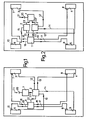
- a master brake cylinder 1 the brake fluid is pressurized in the direction of arrow 21 by actuating the brake pedal 20, and is supplied to the anti-lock modulator 2 via the line 23.
- the modulator has four outputs or an output with a four-way distributor and is connected via lines 12, 13, 14 and 15 to wheels 3, 4, 5 and 6, which are braked by brakes, not shown.
- Each wheel has a sensor 7 to 10, by means of which the deceleration rate of the respective wheel can be measured. From the sensors 7 to 10, signal lines 16 to 19 lead to a detection device 11, in which one of the four sensor signals is selected and converted into a control signal and is supplied via line 22 or 22 'to an anti-lock modulator 2 and / or 2'.
- the least heavily loaded wheel transmits the lowest braking force to the road and its effect will be negligible, especially if braking is too strong - and only for such an anti-lock device is provided. As a consequence, it can be assumed that even blocking this one wheel 5 with the lowest load does not have any negative effects on the braking behavior, the driving stability and the steerability of the vehicle.
- This wheel is recognized by the detection device 11 and switched off from influencing the control. Of the three remaining wheels 3, 4 and 6, one is strong and the other two are less heavily loaded or in good or less good frictional contact with the road.
- both rear wheels would be very weakly loaded in the event of very strong braking, the accidentally weaker one would be eliminated, and the other, which is still insufficient to be used for anti-lock braking, would be too weak braking of the remaining three in this case Effect wheels.
- the brake system on the rear wheels could also be equipped with a brake pressure limiter, which, depending on the vehicle type, limits the brake pressure to a fixed or a load-dependent maximum value.
- this principle can be used not only when cornering but also when there are other different friction conditions of the wheels of a vehicle.
- FIG. 2 shows a brake system with a diagonal division of two brake circuits, largely with the same reference numerals for the same parts as in FIG. 1.
- two anti-lock modulators 2 and 2 ' are connected via two lines 23, 23', each of which has two outputs, the two outputs of a modulator each being connected to two diagonally opposite wheels or their brake cylinders.
Landscapes
- Engineering & Computer Science (AREA)
- Transportation (AREA)
- Mechanical Engineering (AREA)
- Physics & Mathematics (AREA)
- Fluid Mechanics (AREA)
- Regulating Braking Force (AREA)
Claims (5)
Applications Claiming Priority (2)
| Application Number | Priority Date | Filing Date | Title |
|---|---|---|---|
| CH8348/80 | 1980-11-11 | ||
| CH8348/80A CH650734A5 (de) | 1980-11-11 | 1980-11-11 | Antiblockiervorrichtung. |
Publications (3)
| Publication Number | Publication Date |
|---|---|
| EP0051801A2 EP0051801A2 (fr) | 1982-05-19 |
| EP0051801A3 EP0051801A3 (en) | 1985-07-03 |
| EP0051801B1 true EP0051801B1 (fr) | 1987-04-22 |
Family
ID=4338954
Family Applications (1)
| Application Number | Title | Priority Date | Filing Date |
|---|---|---|---|
| EP81109096A Expired EP0051801B1 (fr) | 1980-11-11 | 1981-10-28 | Installation d'antiblocage |
Country Status (4)
| Country | Link |
|---|---|
| US (1) | US4451096A (fr) |
| EP (1) | EP0051801B1 (fr) |
| CH (1) | CH650734A5 (fr) |
| DE (1) | DE3176123D1 (fr) |
Cited By (1)
| Publication number | Priority date | Publication date | Assignee | Title |
|---|---|---|---|---|
| DE4034688C2 (de) * | 1989-11-29 | 2000-06-29 | Nisshin Spinning | Blockiergeschützte, hydraulische Diagonal-Zweikreis-Fahrzeugbremsanlage |
Families Citing this family (29)
| Publication number | Priority date | Publication date | Assignee | Title |
|---|---|---|---|---|
| DE3236534A1 (de) * | 1982-10-02 | 1984-04-05 | Robert Bosch Gmbh, 7000 Stuttgart | Antiblockierregelsystem |
| DE3314802A1 (de) * | 1983-04-23 | 1984-10-31 | Alfred Teves Gmbh, 6000 Frankfurt | Bremsschlupfgeregelte bremsanlage |
| DE3330482A1 (de) * | 1983-08-24 | 1985-03-07 | Alfred Teves Gmbh, 6000 Frankfurt | Verfahren und vorrichtung zur regelung der bremswirkung einer bremsschlupfgeregelten bremsanlage |
| DE3330483A1 (de) * | 1983-08-24 | 1985-03-07 | Alfred Teves Gmbh, 6000 Frankfurt | Bremsschlupfgeregelte bremsanlage fuer kraftfahrzeuge |
| DE3413738C2 (de) * | 1984-04-12 | 1993-11-04 | Teves Gmbh Alfred | Schlupfgeregelte bremsanlage fuer strassenfahrzeuge |
| DE3426455A1 (de) * | 1984-07-18 | 1986-01-30 | Alfred Teves Gmbh, 6000 Frankfurt | Schlupfgeregelte bremsanlage fuer kraftfahrzeuge |
| DE3426456C2 (de) * | 1984-07-18 | 1994-06-16 | Teves Gmbh Alfred | Bremsanlage mit Schlupfregelung |
| DE3430983A1 (de) * | 1984-08-23 | 1986-03-06 | Alfred Teves Gmbh, 6000 Frankfurt | Schaltungsanordnung zur steuerung des ein- und ausrueckens einer kupplung |
| DE3500745A1 (de) * | 1985-01-11 | 1986-07-17 | Alfred Teves Gmbh, 6000 Frankfurt | Verfahren und schaltungsanordnung zur anpassung der schlupfregelung an den momentanen reibwert |
| JPS6291352A (ja) * | 1985-09-13 | 1987-04-25 | Nippon Ee B S Kk | アンチスキツド装置用液圧制御装置 |
| JPS6271748A (ja) * | 1985-09-26 | 1987-04-02 | Nippon Ee B S Kk | アンチスキツド装置用液圧制御装置 |
| DE3671871D1 (de) * | 1985-12-05 | 1990-07-19 | Bosch Gmbh Robert | Antiblockierregelsystem fuer fahrzeuge. |
| DE3605057A1 (de) * | 1986-02-18 | 1987-08-20 | Bosch Gmbh Robert | Blockierschutzbremsanlage |
| JPH0775973B2 (ja) * | 1986-06-09 | 1995-08-16 | 日本エ−ビ−エス株式会社 | アンチスキツド装置用液圧制御装置 |
| JPH0717190B2 (ja) * | 1986-06-11 | 1995-03-01 | 日本エービーエス株式会社 | アンチスキツド装置用液圧制御装置 |
| US4971401A (en) * | 1986-07-31 | 1990-11-20 | Nippon A B S, Ltd. | Anti-skid control apparatus for braking system |
| US4776644A (en) * | 1986-09-05 | 1988-10-11 | Nippon A B S, Ltd. | Anti-skid control apparatus for a vehicle braking system |
| US4755945A (en) * | 1986-09-24 | 1988-07-05 | General Motors Corporation | Adaptive mode anti-lock brake controller |
| US4753493A (en) * | 1986-10-08 | 1988-06-28 | Nippon A B S, Ltd. | Anti-skid control apparatus for a vehicle braking system |
| JPH0775974B2 (ja) * | 1986-10-16 | 1995-08-16 | 日本エ−ビ−エス株式会社 | アンチスキツド装置用液圧制御装置 |
| JPS63130457A (ja) * | 1986-11-19 | 1988-06-02 | Nippon Ee B S Kk | アンチスキツド装置用液圧制御装置 |
| JPH0620880B2 (ja) * | 1987-01-26 | 1994-03-23 | 本田技研工業株式会社 | 車両のアンチロツク制御方法 |
| GB2200701B (en) * | 1987-02-09 | 1991-12-18 | Nippon Abs Ltd | Anti-skid braking system for vehicles. |
| JPH089325B2 (ja) * | 1987-02-18 | 1996-01-31 | 日本エ−ビ−エス株式会社 | アンチスキッド装置用液圧制御装置 |
| JP2689405B2 (ja) * | 1988-12-24 | 1997-12-10 | 住友電気工業株式会社 | アンチロック制御装置 |
| DE4023950C2 (de) * | 1989-07-31 | 1997-03-13 | Nippon Abs Ltd | Antiblockiersystems für ein Fahrzeug mit zwei Vorderrädern und zwei Hinterrädern, die jeweils paarweise diagonal in einem Zweikreis-Bremssystem miteinander verbunden sind |
| JP3144557B2 (ja) * | 1990-05-09 | 2001-03-12 | 曙ブレーキ工業株式会社 | 車両のアンチロック制御方法 |
| US5033002A (en) * | 1990-06-11 | 1991-07-16 | Ford Motor Company | Vehicle traction controller/road friction and hill slope tracking system |
| GB2454223B (en) | 2007-11-01 | 2011-09-21 | Haldex Brake Products Ltd | Vehicle stability control method |
Citations (2)
| Publication number | Priority date | Publication date | Assignee | Title |
|---|---|---|---|---|
| US794389A (en) * | 1904-02-04 | 1905-07-11 | Nat Tube Co | Cutting-off machine. |
| US2840278A (en) * | 1956-12-18 | 1958-06-24 | United States Borax Chem | Valve adapted for use in powder dispensers |
Family Cites Families (12)
| Publication number | Priority date | Publication date | Assignee | Title |
|---|---|---|---|---|
| US3493271A (en) * | 1967-10-23 | 1970-02-03 | Chrysler Corp | Anti-skid system |
| US3450444A (en) * | 1968-02-09 | 1969-06-17 | Hurst Campbell Inc | Anti-skid system |
| GB1259629A (fr) * | 1968-03-22 | 1972-01-05 | ||
| DE2119590A1 (de) * | 1971-04-22 | 1972-11-02 | Teldix Gmbh, 6900 Heidelberg | Antiblockierregelsystem für die gemeinsame Regulierung des Bremsdruckes an den Rädern einer Fahrzeugachse |
| US3764182A (en) * | 1971-06-23 | 1973-10-09 | Philco Ford Corp | Automotive anti-skid braking |
| DE2231166C2 (de) * | 1972-06-26 | 1985-02-14 | Robert Bosch Gmbh, 7000 Stuttgart | Antiblockierregelsystem für druckmittelbetätigte Fahrzeugbremsen |
| DE2243260A1 (de) * | 1972-09-02 | 1974-03-07 | Teldix Gmbh | Antiblockierregelsystem fuer die gemeinsame regulierung des bremsdruckes an mehreren raedern |
| DE2259929A1 (de) * | 1972-12-07 | 1974-06-27 | Teldix Gmbh | Antiblockierregelsystem |
| US3794389A (en) * | 1972-12-21 | 1974-02-26 | Bendix Corp | Adaptive braking system |
| US3802749A (en) * | 1973-05-04 | 1974-04-09 | Bendix Corp | Adaptive braking system control wheel selection by velocity comparison |
| DE2518196C2 (de) * | 1975-04-24 | 1986-10-09 | Robert Bosch Gmbh, 7000 Stuttgart | Steueranordnung in einem Antiblockierregelsystem für Fahrzeuge |
| GB1581943A (en) * | 1977-04-12 | 1980-12-31 | Bosch Gmbh Robert | Anti-lock ontrol systems for braking systems for vehicles |
-
1980
- 1980-11-11 CH CH8348/80A patent/CH650734A5/de not_active IP Right Cessation
-
1981
- 1981-10-28 DE DE8181109096T patent/DE3176123D1/de not_active Expired
- 1981-10-28 EP EP81109096A patent/EP0051801B1/fr not_active Expired
- 1981-11-10 US US06/320,137 patent/US4451096A/en not_active Expired - Lifetime
Patent Citations (2)
| Publication number | Priority date | Publication date | Assignee | Title |
|---|---|---|---|---|
| US794389A (en) * | 1904-02-04 | 1905-07-11 | Nat Tube Co | Cutting-off machine. |
| US2840278A (en) * | 1956-12-18 | 1958-06-24 | United States Borax Chem | Valve adapted for use in powder dispensers |
Cited By (1)
| Publication number | Priority date | Publication date | Assignee | Title |
|---|---|---|---|---|
| DE4034688C2 (de) * | 1989-11-29 | 2000-06-29 | Nisshin Spinning | Blockiergeschützte, hydraulische Diagonal-Zweikreis-Fahrzeugbremsanlage |
Also Published As
| Publication number | Publication date |
|---|---|
| US4451096A (en) | 1984-05-29 |
| EP0051801A3 (en) | 1985-07-03 |
| EP0051801A2 (fr) | 1982-05-19 |
| DE3176123D1 (de) | 1987-05-27 |
| CH650734A5 (de) | 1985-08-15 |
Similar Documents
| Publication | Publication Date | Title |
|---|---|---|
| EP0051801B1 (fr) | Installation d'antiblocage | |
| DE3413738C2 (de) | Schlupfgeregelte bremsanlage fuer strassenfahrzeuge | |
| EP0529280B1 (fr) | Installation de réglage de la pression de freinage dans un véhicule automobile | |
| EP0512216B1 (fr) | Véhicule avec essieu auto-pivotable rétractable | |
| DE102015015922A1 (de) | Verfahren zum Einstellen von Bremsdrücken an pneumatisch betätigten Radbremsen eines Fahrzeugs, Bremsanlage zur Durchführung des Verfahrens sowie Fahrzeug | |
| DE3502051A1 (de) | Bremsdruckregeleinrichtung | |
| DE3201047C2 (fr) | ||
| EP2049372B1 (fr) | Procédé de distribution de la pression de freinage aux essieux d'un véhicule | |
| DE2757911A1 (de) | Blockierschutz-regeleinrichtung | |
| DE3627550C2 (fr) | ||
| DE4036940A1 (de) | Bremsanlage fuer ein fahrzeug | |
| EP0209664B1 (fr) | Système d'anti-blocage | |
| DE2424217A1 (de) | Antiblockierregelsystem fuer vierradfahrzeuge | |
| DE2610585A1 (de) | Blockierschutz-regeleinrichtung fuer kraftfahrzeuge | |
| DE3805087A1 (de) | Blockierschutzeinrichtung fuer ein fahrzeugbremssystem | |
| DE2545593A1 (de) | Blockierschutzregelsystem | |
| DE2933085C2 (fr) | ||
| DE3201045A1 (de) | "antiblockiersystem fuer fahrzeuge" | |
| EP0002073B1 (fr) | Dispositif de commande pour un essieu relevable d'un véhicule utilitaire | |
| DE4014295A1 (de) | Hydraulische zweikreisbremsanlage | |
| DE19713920A1 (de) | Verfahren zur Abbremsung eines Fahrzeugs | |
| EP0487862B1 (fr) | Système antiblocage pour véhicules à traction sur les quatres roues | |
| EP0882631B1 (fr) | Procédé de freinage d'un véhicule | |
| DE3505268C2 (de) | Blockierschutzelektronik für ein Straßenfahrzeug | |
| DE3737316A1 (de) | Schlupfgeregelte hydraulische kraftfahrzeug-bremsanlage |
Legal Events
| Date | Code | Title | Description |
|---|---|---|---|
| PUAI | Public reference made under article 153(3) epc to a published international application that has entered the european phase |
Free format text: ORIGINAL CODE: 0009012 |
|
| AK | Designated contracting states |
Designated state(s): DE FR GB IT SE |
|
| RAP1 | Party data changed (applicant data changed or rights of an application transferred) |
Owner name: ALFRED TEVES GMBH |
|
| 17P | Request for examination filed |
Effective date: 19840919 |
|
| PUAL | Search report despatched |
Free format text: ORIGINAL CODE: 0009013 |
|
| AK | Designated contracting states |
Designated state(s): DE FR GB IT SE |
|
| 17Q | First examination report despatched |
Effective date: 19860922 |
|
| GRAA | (expected) grant |
Free format text: ORIGINAL CODE: 0009210 |
|
| AK | Designated contracting states |
Kind code of ref document: B1 Designated state(s): DE FR GB IT SE |
|
| REF | Corresponds to: |
Ref document number: 3176123 Country of ref document: DE Date of ref document: 19870527 |
|
| ITF | It: translation for a ep patent filed | ||
| ET | Fr: translation filed | ||
| PLBI | Opposition filed |
Free format text: ORIGINAL CODE: 0009260 |
|
| 26 | Opposition filed |
Opponent name: KNORR-BREMSE AG Effective date: 19880122 |
|
| PLBN | Opposition rejected |
Free format text: ORIGINAL CODE: 0009273 |
|
| STAA | Information on the status of an ep patent application or granted ep patent |
Free format text: STATUS: OPPOSITION REJECTED |
|
| 27O | Opposition rejected |
Effective date: 19891223 |
|
| ITTA | It: last paid annual fee | ||
| EAL | Se: european patent in force in sweden |
Ref document number: 81109096.8 |
|
| PGFP | Annual fee paid to national office [announced via postgrant information from national office to epo] |
Ref country code: DE Payment date: 19981207 Year of fee payment: 18 |
|
| PGFP | Annual fee paid to national office [announced via postgrant information from national office to epo] |
Ref country code: GB Payment date: 19990921 Year of fee payment: 19 |
|
| PGFP | Annual fee paid to national office [announced via postgrant information from national office to epo] |
Ref country code: FR Payment date: 19991018 Year of fee payment: 19 |
|
| PGFP | Annual fee paid to national office [announced via postgrant information from national office to epo] |
Ref country code: SE Payment date: 19991028 Year of fee payment: 19 |
|
| PG25 | Lapsed in a contracting state [announced via postgrant information from national office to epo] |
Ref country code: DE Free format text: LAPSE BECAUSE OF NON-PAYMENT OF DUE FEES Effective date: 20000801 |
|
| PG25 | Lapsed in a contracting state [announced via postgrant information from national office to epo] |
Ref country code: GB Free format text: LAPSE BECAUSE OF NON-PAYMENT OF DUE FEES Effective date: 20001028 |
|
| PG25 | Lapsed in a contracting state [announced via postgrant information from national office to epo] |
Ref country code: SE Free format text: THE PATENT HAS BEEN ANNULLED BY A DECISION OF A NATIONAL AUTHORITY Effective date: 20001030 |
|
| EUG | Se: european patent has lapsed |
Ref document number: 81109096.8 |
|
| GBPC | Gb: european patent ceased through non-payment of renewal fee |
Effective date: 20001028 |
|
| PG25 | Lapsed in a contracting state [announced via postgrant information from national office to epo] |
Ref country code: FR Free format text: LAPSE BECAUSE OF NON-PAYMENT OF DUE FEES Effective date: 20010629 |
|
| REG | Reference to a national code |
Ref country code: FR Ref legal event code: ST |