EP0530485A2 - Durch Zusammendrücken lösbare Schnellverbindung - Google Patents
Durch Zusammendrücken lösbare Schnellverbindung Download PDFInfo
- Publication number
- EP0530485A2 EP0530485A2 EP92112668A EP92112668A EP0530485A2 EP 0530485 A2 EP0530485 A2 EP 0530485A2 EP 92112668 A EP92112668 A EP 92112668A EP 92112668 A EP92112668 A EP 92112668A EP 0530485 A2 EP0530485 A2 EP 0530485A2
- Authority
- EP
- European Patent Office
- Prior art keywords
- body portion
- retaining ring
- quick connector
- axially
- beam members
- Prior art date
- Legal status (The legal status is an assumption and is not a legal conclusion. Google has not performed a legal analysis and makes no representation as to the accuracy of the status listed.)
- Granted
Links
Images

Classifications
-
- F—MECHANICAL ENGINEERING; LIGHTING; HEATING; WEAPONS; BLASTING
- F16—ENGINEERING ELEMENTS AND UNITS; GENERAL MEASURES FOR PRODUCING AND MAINTAINING EFFECTIVE FUNCTIONING OF MACHINES OR INSTALLATIONS; THERMAL INSULATION IN GENERAL
- F16L—PIPES; JOINTS OR FITTINGS FOR PIPES; SUPPORTS FOR PIPES, CABLES OR PROTECTIVE TUBING; MEANS FOR THERMAL INSULATION IN GENERAL
- F16L37/00—Couplings of the quick-acting type
- F16L37/08—Couplings of the quick-acting type in which the connection between abutting or axially overlapping ends is maintained by locking members
- F16L37/084—Couplings of the quick-acting type in which the connection between abutting or axially overlapping ends is maintained by locking members combined with automatic locking
-
- Y—GENERAL TAGGING OF NEW TECHNOLOGICAL DEVELOPMENTS; GENERAL TAGGING OF CROSS-SECTIONAL TECHNOLOGIES SPANNING OVER SEVERAL SECTIONS OF THE IPC; TECHNICAL SUBJECTS COVERED BY FORMER USPC CROSS-REFERENCE ART COLLECTIONS [XRACs] AND DIGESTS
- Y10—TECHNICAL SUBJECTS COVERED BY FORMER USPC
- Y10S—TECHNICAL SUBJECTS COVERED BY FORMER USPC CROSS-REFERENCE ART COLLECTIONS [XRACs] AND DIGESTS
- Y10S285/00—Pipe joints or couplings
- Y10S285/921—Snap-fit
Definitions
- the present invention relates to snap-fit connectors, and more particularly to such connectors which are employed in fluid conduit systems to facilitate assembly and disassembly.
- Snap-fit or quick connectors have been found to be useful in a wide range of applications. In particular, they are frequently employed for joining fluid carrying conduit in automotive and industrial applications. Such connectors have found general acceptance in as they are typically capable of being closed in a single uniaxial movement which facilitates automated assembly, and entail simple designs which are relatively inexpensive to produce.
- a further advantage of quick connect fittings is that they provide an effective seal for handling volatile or hazardous fluids such as gasoline while permitting ease of disassembly and reassembly during repair of a host system.
- tools are often required to effect release of quick connect fittings, designs such as those described in United States patents 3,990,727 and 4,844,512 provide for manual release of the fitting without the necessity of separate tools.
- squeeze-to-release designs often have certain shortcomings.
- the present invention overcomes the above described shortcomings of the prior art by providing a connector which is suitable for long term operation, is inexpensive to manufacture, is compact and is capable of being assembled by robots.
- the inventive quick connector is adapted for selective locking engagement with a male member of the type including an outwardly extending abutment surface.
- the connector includes a generally cylindrical, elongated body portion which is open at one end for receiving the male member and has a conduit receiving adapter formed at the other end.
- An annular retaining ring is disposed concentrically with the body portion axially spaced from the open end and is attached thereto by two circumferentially opposed generally parallel, axially elongated beam members.
- Each beam member is affixed at one end to the retaining ring and at the other end to a mount located on the outside surface of the body portion axially spaced from the open end.
- two or more circumferentially spaced detents extend inwardly from the retaining ring which are operative to capture the abutment surface of the male member to effect positive axial engagement therebetween.
- the beam members extend axially a distance approximately equal to the characteristic inner diameter the body portion.
- the associated male member comprises a tubular conduit with a circumferential radially outwardly extending upset located adjacent and end thereof to define the male abutment surface.
- the beam members extend generally parallel to the outside surface of the body portion and are spaced slightly radially outwardly therefrom. This arrangement has the advantage of providing a relatively compact design suitable for incorporation in a close quarter environment.
- the present invention will be described in detail hereinbelow adapted for incorporation within a system of tubular conduits for conducting fluid flow. However, it is contemplated that in the broadest sense, the present inventive connector could be readily adapted for other applications in view of the present specification.
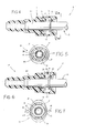
- Female connector part 11 includes a generally cylindrical elongated body portion 13 having a stepped bore 14 extending therethrough concentric with the body portion axis of elongation. As best seen in Figure 3, bore 14 exits rightwardly from body portion 13 to define an opening 15 for receiving male connector part 12. Body portion 13 transitions leftwardly into a conduit receiving adapter 16 which is generally tubular and through which bore 14 emerges leftwardly. The outer surface of adapter 16 defines two or more circumferential barbs 17 axially spaced therealong for engaging the inner diameter of a rubber or otherwise suitable conduit (not shown) in the usual manner.
- a central segment 18 of stepped bore 14 is dimensioned to form a slip fit with the nominal outside diameter of male connector part 12, as best shown in Figure 4.
- a radial step 19 delineates central segment 18 with a left reduced diameter segment 20 of bore 14 extending through adapter 16. Step 19 serves as an abutment surface for the leading edge of male connector part 12.
- a second radial step 21 delineates central segment 18 and a right increased diameter segment 22 of bore 14 which emerges rightwardly as opening 15.
- a radially inwardly directed circumferential retaining rib 23 is formed within bore segment 22 axially interspaced between step 21 and opening 15. The radially outwardmost portion of bore segment 22 intermediate step 21 and rib 23 is designated as a seal receiving recess 24.
- annular elastic seal such as an O-ring (see Figure 4) would be disposed within recess 24 and retained in position by rib 23 for providing sealing engagement between bore 14 of body portion 13 and the outer diameter surface of male connector part 12.
- An annular retaining ring 25 is disposed concentrically about the axis of elongation of body portion 13 and is axially spaced rightwardly (as viewed in Figure 3) from opening 15.
- the degree of axial spacing between retaining ring 25 and opening 15 is not deemed critical. The two need only by separated sufficiently to ensure that ring 25 can be manipulated without interference from the adjacent end of body portion 13. In the preferred embodiment, sufficient spacing is provided to accommodate an upset or flange of male connector part 12.
- Retaining ring 25 is joined with the remainder of connector part 11 by two circumferentially opposed, generally parallel, axially elongated beam members 26 and 27. Beam members 26 and 27 are each joined at one end to the transverse face of retaining ring 25 nearest opening 15.
- beam members 26 and 27 are joined to body portion 13 through intermediate respective mounting bosses 28 and 29 extending radially outwardly from body portion 13.
- beam members have a pentagon-shaped cross-section as seen in Figures 2 and 8.
- rhombic, diamond, lozenge or similar cross-section profiles could be substituted.
- Retaining ring 25 has a central opening 30 which has a characteristic diameter exceeding that of bore segment 22 for providing clearance for male connector part 12 as best viewed in Figures 4 through 7.
- Two circumferentially spaced detents extend radially inwardly from retaining ring 25 within central opening 30. Each detent is angularly aligned with one of the beam members 26, 27 (see Figure 2) and forms a radially tapering ramp surface 32 on a side of each detent 31 facing away from opening 15 and a radially transverse abutment surface 33 on a side thereof facing opening 15.
- Detents 31 extend radially inwardly within central opening 30 such as to have a diametrical spacing therebetween which is greater than the diameter of bore segment 18 and slightly less than the diameter of bore segment 22 which, as viewed in Figure 3, is designated D.
- Beam members 26 and 27 extend an axial length designated L between retaining ring 25 and mounting bosses 28 and 29, respectively. As will be described in detail hereinbelow, in the preferred embodiment of the invention, dimensions D and L are generally equal.
- mounting bosses 28 and 29 are axially positioned intermediate opening 15 and adapter 16, preferably axially coextensive with radial Step 21 of body portion 13.
- Such positioning provides a substantially rigid base for mounting beam members 26 and 27 which is well spaced axially leftwardly from opening 15 to permit distention of retaining ring 25, as will be described in detail hereinbelow without distortion of the open end of body portion 13. Furthermore, beam members are spaced radially outwardly of and generally parallel to (in the relaxed condition) body portion 13, and transition into bosses 28, 29 and retaining ring 25 through contoured tapers to avoid abrupt transitions which can create stress raisers.
- retaining ring 25 is provided with a specific profile in the transverse plane to enhance its advantageous operation as described herein.
- retaining ring 25 is preferably formed from upper and lower crescent portions 34 and 35 joined at the ends thereof through web members 37 and 38.
- the thickest section of crescent portions 34 and 35 is formed in the circumferential center thereof to positionally coincide or angularly align with beam members 26 and 27, respectively.
- Web members 36 and 37 are locally thickened to provide relatively flat grip surfaces 38 and 39, respectively, which can be serrated or dimpled to enhance their gripworthiness.
- the entire female connector part 11 is preferably injection molded as a single homogeneous piece from suitable material such as Nylon 66 unfilled. Although many materials would be suitable for practicing the present invention, Nylon 66 has been found to be particularly advantageous in certain automotive applications.
- suitable material such as Nylon 66 unfilled.
- Nylon 66 has been found to be particularly advantageous in certain automotive applications.
- the retaining ring 25 is configured as described hereinabove, the portions thereof adjacent beam members 26 and 27 are relatively stiff while web members 36 and 37 are relatively compliant.
- connector assembly 10 can be released to enable uniaxial separation of female connector part 11 and male connector part 12 simply by grasping and squeezing together of grip surfaces 38 and 39.
- the crescent- shape configuration furthermore provides for greater travel of web members 36 and 37 from their illustrated relaxed position in which detents 31 engage the male connector part 12 to a release condition in which detents 31 are momentarily radially displaced outwardly to effect release of the male connector part 12.
- This configuration has been found to provide substantially easier release of the connector assembly 10 as compared to prior art approaches involving release rings with uniform diameter and/or cross-sectional area.
- male connector part 11 is a standard tube end with an upset or radially outwardly extending circumferential ridge formed therein adjacent and end which is matingly received within bore 14 of connector part 11.
- male connector part 12 includes a leading end 40 with a conventional upset 41 positioned slightly rearwardly therefrom.
- the leading edge of upset 41 comprises a ramp surface 42 and the trailing edge thereof comprises an abutment surface 43.
- male connector part 12 engages female part 11 whereby ramp surface 42 engages ramp surface 32 of detents 31 to momentarily distend retaining ring 25 until upset 41 passes leftwardly of abutment surface 33.
- the natural resiliency of the material of retaining ring 25 causes it to reassume its original shape whereinafter removal of male part 12 is prevented by engagement of abutment surfaces 33 and 43.
- Connector assembly 10 is decoupled by the application of fingertip pressure radially inwardly at gripping surfaces 38 and 39 as illustrated by arrows 44 in Figure 7. As described hereinabove, the application of such pressure distends retaining ring 25, causing detents 31 to move radially outwardly as best seen in Figure 6. Once the innermost portion of detents 31 is positioned radially outwardly of upset 41, male connector part 12 can be decoupled from female connector part 11 by axially withdrawing it in the usual manner.
- a principle advantage of the present invention lies in the provision of beam members 26 and 27 in that the respective ends thereof find relatively rigid support in either the thickest sectioned area of the retaining ring 25 or the mounting boss 28, 29. This permits distention of retaining ring 25 from the configuration shown in Figures 4 and 5 to the configuration shown in Figure 6 and 7 with the application of relatively little effort by the user while, simultaneously, maintaining structural rigidity both at the opening 15 as well as the circumferential positioning of detents 31. This represents a substantial improvement over known prior art designs which either are so rigid as to make release extremely difficult and require the exercise of large effort or, so flimsy that the detents tend to self- rotate in distortion and not release the male part.
- Such self-rotation can be envision by a slight rotation of each detent 31, causing a corner of each abutment surface 33 to remain engaged with abutment surface 42 of male part 12.
- the propensity of such circumferential distortion is substantially reduced with the present design.
- many prior art designs tend to have large inherent stress risers, resulting in premature fracture failures.
- the provision of relatively long beam members 26 and 28 in the present invention distributes the forces of distention along the beam and significantly reduces the likelihood of failure while permitting great design flexibility in material selection for specific applications.
- a circumferential skirt 45 extends axially outwardly from detents 31 to serve as a guide for leading end 40 of male part 12 during the insertion process, as well as permitting use of a reduced overall wall thickness in retaining ring 25 to further enhance ease of decoupling without degrading pull-apart strength.
- a beam member is deemed to be any structure that functions as a load disturbing beam subjected primarily to bending rather than tension and compression which is connected at one point to the body portion and at another point to the retaining ring. Accordingly, the foregoing is not to be construed in a limiting sense.
Landscapes
- Engineering & Computer Science (AREA)
- General Engineering & Computer Science (AREA)
- Mechanical Engineering (AREA)
- Quick-Acting Or Multi-Walled Pipe Joints (AREA)
Applications Claiming Priority (2)
| Application Number | Priority Date | Filing Date | Title |
|---|---|---|---|
| US07/753,758 US5213376A (en) | 1991-09-03 | 1991-09-03 | Squeeze-to-release quick connector |
| US753758 | 1991-09-03 |
Publications (3)
| Publication Number | Publication Date |
|---|---|
| EP0530485A2 true EP0530485A2 (de) | 1993-03-10 |
| EP0530485A3 EP0530485A3 (en) | 1993-04-21 |
| EP0530485B1 EP0530485B1 (de) | 1996-05-15 |
Family
ID=25032033
Family Applications (1)
| Application Number | Title | Priority Date | Filing Date |
|---|---|---|---|
| EP92112668A Expired - Lifetime EP0530485B1 (de) | 1991-09-03 | 1992-07-24 | Durch Zusammendrücken lösbare Schnellverbindung |
Country Status (4)
| Country | Link |
|---|---|
| US (1) | US5213376A (de) |
| EP (1) | EP0530485B1 (de) |
| DE (1) | DE69210719T2 (de) |
| ES (1) | ES2087361T3 (de) |
Cited By (10)
| Publication number | Priority date | Publication date | Assignee | Title |
|---|---|---|---|---|
| EP0679828A1 (de) * | 1994-04-28 | 1995-11-02 | Kaltenbach & Voigt Gmbh & Co. | Steckverbindung, insbesondere für eine pneumatische, hydraulische oder elektrische Verbindungsleitung |
| EP0680736A1 (de) * | 1994-05-06 | 1995-11-08 | E.R. Squibb & Sons, Inc. | Ostomiekupplung |
| CN1044034C (zh) * | 1994-04-27 | 1999-07-07 | 樱护谟株式会社 | 连接装置 |
| EP0982525A1 (de) * | 1998-08-25 | 2000-03-01 | Nobel Plastiques | Einteilige Schnappkupplung |
| WO2002037014A1 (fr) | 2000-11-03 | 2002-05-10 | Nobel Plastiques | Raccord encliquetable monocorps |
| FR2829554A1 (fr) | 2001-09-13 | 2003-03-14 | Nobel Plastiques | Raccord encliquetable monocorps |
| EP0691501B2 (de) † | 1994-07-08 | 2004-03-24 | Voss Automotive GmbH | Steckverbinder für Schlauch- und/oder Rohrleitungen |
| FR2850155A1 (fr) * | 2003-01-16 | 2004-07-23 | Cf Gomma Spa | Dispositif de connexion pour le degazage |
| DE10156750B4 (de) * | 2000-11-22 | 2009-09-03 | Draeger Ltd., Blyth | Schließverbindung zwischen Atemgasversorgung und Atemmaske |
| FR2963078A1 (fr) * | 2010-07-21 | 2012-01-27 | Delfingen Fr Anteuil Sa | Tube destine a recevoir une tubulure telle qu'un connecteur |
Families Citing this family (62)
| Publication number | Priority date | Publication date | Assignee | Title |
|---|---|---|---|---|
| US5277402A (en) * | 1991-10-08 | 1994-01-11 | Itt Corporation | Quick connect fluid coupling with check valve |
| IL105065A (en) * | 1992-03-28 | 1995-05-26 | Smiths Ind Public Ltd | author |
| US5466017A (en) * | 1993-09-17 | 1995-11-14 | Itt Corporation | Squeeze-to-release quick connector |
| US5378025A (en) * | 1993-11-03 | 1995-01-03 | Itt Corporation | Quick connector with integral release member |
| DE4344665A1 (de) * | 1993-12-27 | 1995-06-29 | Raymond A & Cie | Schutzkappe für eine lösbare Schnellschlußkupplung |
| FR2721088B1 (fr) * | 1994-06-10 | 1997-09-12 | Bosch Gmbh Robert | Raccord de conduites de carburant comportant un ajutage et un dispositif de son blocage axial dans le perçage de branchement. |
| WO1996008078A1 (en) * | 1994-09-02 | 1996-03-14 | Philips Electronics N.V. | Receiver with quadrature decimation stage, method of processing digital signals |
| US5537727A (en) * | 1994-09-28 | 1996-07-23 | Itt Corporation | Release tool for quick connector with integral release member |
| US5533761A (en) * | 1994-10-26 | 1996-07-09 | Itt Corporation | Quick connector release member |
| US5568946A (en) | 1994-12-14 | 1996-10-29 | Itt Corporation | Squeeze-to-release quick connector with snap-in retainer |
| US5951063A (en) * | 1995-06-07 | 1999-09-14 | Itt Manufacturing Enterprises, Inc. | Quick connector with snap-on retainer having enhanced engagement |
| US5742976A (en) * | 1995-12-18 | 1998-04-28 | Black & Decker Inc. | Holding device for an end of a hose in a vacuum apparatus |
| US5711553A (en) * | 1996-09-04 | 1998-01-27 | Stmc-Llc | Quick connect fluid coupling |
| US5873610A (en) * | 1996-12-19 | 1999-02-23 | Itt Automotive, Inc. | Female connector member for large tolerance male member endforms |
| US5897142A (en) * | 1996-12-19 | 1999-04-27 | Itt Automotive, Inc. | Push-to-release quick connector |
| US5823508A (en) * | 1996-12-20 | 1998-10-20 | Itt Automotive, Inc. | One piece quick connect |
| US5863077A (en) * | 1996-12-20 | 1999-01-26 | Itt Automotive, Inc. | Quick connector with snap-on frangible retainer |
| US6293596B1 (en) | 1999-01-06 | 2001-09-25 | Itt Manufacturing Enterprises, Inc. | Quick connector with after incident indicator clip |
| JP2000274579A (ja) * | 1999-03-24 | 2000-10-03 | Nifco Inc | チューブ |
| JP3771745B2 (ja) * | 1999-04-15 | 2006-04-26 | 松下電器産業株式会社 | セラミックグリーンシートの孔明け加工用シート押えおよび孔明け装置 |
| JP3724360B2 (ja) * | 1999-11-09 | 2005-12-07 | 東海ゴム工業株式会社 | コネクタ |
| US6688654B2 (en) * | 2000-12-08 | 2004-02-10 | Newfrey Llc | One piece quick connector |
| ATE278141T1 (de) * | 2000-12-15 | 2004-10-15 | Zodiac Pool Care Europe Sas | Drehkupplung für eine rohrleitung |
| US6802491B1 (en) | 2002-04-30 | 2004-10-12 | Itt Manufacturing Enterprises, Inc. | Fluid shut off valve cartridge with quick connection |
| FR2845607B1 (fr) * | 2002-10-10 | 2005-06-24 | Vygon | Connecteur de fluide a usage medical et ses applications |
| US7413366B2 (en) * | 2003-12-09 | 2008-08-19 | Unger Marketing International, Llc | Connecting members and methods for connecting implements to extension poles |
| JP2006200738A (ja) * | 2004-12-24 | 2006-08-03 | Tokai Rubber Ind Ltd | 流体輸送用のチューブ |
| USD639398S1 (en) * | 2006-07-26 | 2011-06-07 | Colder Products Company | Fluid coupling |
| WO2008079828A2 (en) * | 2006-12-20 | 2008-07-03 | Onset Medical Corporation | Expandable trans-septal sheath |
| US20090188575A1 (en) * | 2008-01-28 | 2009-07-30 | Colder Products Company | Quick Connect/Disconnect Coupling Assemblies |
| US7954515B2 (en) * | 2008-08-15 | 2011-06-07 | Colder Products Company | Combination cap and plug assembly |
| USD612019S1 (en) | 2009-01-28 | 2010-03-16 | Colder Products Company | Coupling body |
| USD602128S1 (en) | 2009-01-28 | 2009-10-13 | Colder Products Company | Coupling insert |
| US10441120B1 (en) | 2010-04-30 | 2019-10-15 | Unger Marketing International, Llc | Universal connecting members |
| USD634087S1 (en) | 2010-04-30 | 2011-03-08 | Unger Marketing International, Llc | Cleaning tool grip |
| DE102010035027A1 (de) | 2010-08-20 | 2012-02-23 | Voss Automotive Gmbh | Verriegelungselement für einen Steckverbinder und Steckverbinder mit einem solchen Verriegelungselement |
| CA3177636A1 (en) | 2011-06-03 | 2012-12-06 | Fisher & Paykel Healthcare Limited | Medical tubes and methods of manufacture |
| US9649436B2 (en) | 2011-09-21 | 2017-05-16 | Bayer Healthcare Llc | Assembly method for a fluid pump device for a continuous multi-fluid delivery system |
| GB2541301B (en) | 2012-03-15 | 2017-07-12 | Fisher & Paykel Healthcare Ltd | Respiratory gas humidification system |
| GB2577634B (en) | 2012-04-27 | 2020-09-30 | Fisher & Paykel Healthcare Ltd | Respiratory humidification apparatus |
| CN104955510B (zh) | 2012-11-14 | 2017-05-10 | 费雪派克医疗保健有限公司 | 用于呼吸回路的分区加热 |
| JP6412879B2 (ja) | 2012-12-04 | 2018-10-24 | フィッシャー アンド ペイケル ヘルスケア リミテッド | 医療用チューブおよびその製造方法 |
| GB2583046B8 (en) | 2013-09-13 | 2021-04-28 | Fisher & Paykel Healthcare Ltd | Resilient probe mount for a humidification system |
| EP3622993B8 (de) | 2013-09-13 | 2021-08-25 | Fisher & Paykel Healthcare Limited | Heizsockel mit einem schutz zur steuerung der bewegung einer befeuchterkammer |
| US10814091B2 (en) | 2013-10-24 | 2020-10-27 | Fisher & Paykel Healthcare Limited | System for delivery of respiratory gases |
| GB2558102B (en) | 2013-12-20 | 2018-11-28 | Fisher & Paykel Healthcare Ltd | Humidification system connections |
| US10449319B2 (en) | 2014-02-07 | 2019-10-22 | Fisher & Paykel Healthcare Limited | Respiratory humidification system |
| CN111265754B (zh) | 2014-03-17 | 2023-06-06 | 费雪派克医疗保健有限公司 | 用于呼吸系统的医用管 |
| WO2015167347A1 (en) | 2014-05-02 | 2015-11-05 | Fisher & Paykel Healthcare Limited | Gas humidification arrangement |
| EP3142737B1 (de) | 2014-05-13 | 2020-07-08 | Fisher & Paykel Healthcare Limited | Eine anschlusskappe für eine vorrichtung zum anfeuchten von gasen und eine vorrichtung zum anfeuchten von gasen |
| EP3607988B1 (de) | 2014-06-03 | 2025-09-10 | Fisher & Paykel Healthcare Limited | Befeuchtungskammer für eine atemtherapievorrichtung |
| EP3220992B1 (de) | 2014-11-17 | 2021-06-23 | Fisher & Paykel Healthcare Limited | Befeuchtung von atemgasen |
| ES3030489T3 (en) | 2015-01-09 | 2025-06-30 | Bayer Healthcare Llc | Multiple fluid delivery system with multi-use disposable set and features thereof |
| US10385999B2 (en) * | 2015-07-09 | 2019-08-20 | Terumo Cardiovascular Systems Corporation | Fluid coupling devices |
| JP7014717B2 (ja) | 2015-09-09 | 2022-02-01 | フィッシャー アンド ペイケル ヘルスケア リミテッド | 呼吸回路用の区域加熱 |
| SG10202106016TA (en) | 2016-12-07 | 2021-07-29 | Fisher and paykel healthcare ltd | Sensing arrangements for medical devices |
| US11311695B2 (en) | 2016-12-22 | 2022-04-26 | Fisher & Paykel Healthcare Limited | Medical tubes and methods of manufacture |
| BR112020022834A2 (pt) * | 2018-05-08 | 2021-02-02 | Baylis Medical Company Inc. | mecanismos de acoplamento para dispositivos |
| USD937411S1 (en) | 2019-08-30 | 2021-11-30 | Fisher & Paykel Healthcare Limited | Unit end connector |
| EP3812599B1 (de) * | 2019-10-24 | 2024-10-02 | Illinois Tool Works Inc. | Befestigungsmittel und ein teil damit |
| DE202020003252U1 (de) | 2020-07-29 | 2021-11-02 | Till Geier | Vorrichtung zur Erzeugung stehender Wellen |
| US20250216013A1 (en) * | 2023-12-30 | 2025-07-03 | Cooper-Standard Automotive Inc. | Two-Sided Adaptor |
Family Cites Families (6)
| Publication number | Priority date | Publication date | Assignee | Title |
|---|---|---|---|---|
| US3588149A (en) * | 1969-08-13 | 1971-06-28 | Amp Inc | Vacuum or pressure coupling devices |
| US3990727A (en) * | 1976-01-26 | 1976-11-09 | Stephen Franics Gallagher | Quick detachable coupler |
| FR2617943B1 (fr) * | 1987-07-06 | 1990-10-05 | Inventa Ag | Raccord rapide destine a relier une conduite flexible ou rigide |
| US4793639A (en) * | 1988-04-29 | 1988-12-27 | Chrysler Motors Corporation | Tube coupling mechanism |
| JPH0674875B2 (ja) * | 1988-12-07 | 1994-09-21 | エムス − インヴエンタ・アクチエンゲゼルシヤフト | 迅速断ち継ぎ継手 |
| GB2227064B (en) * | 1988-12-07 | 1992-08-05 | Inventa Ag | Pipe connector |
-
1991
- 1991-09-03 US US07/753,758 patent/US5213376A/en not_active Expired - Lifetime
-
1992
- 1992-07-24 DE DE69210719T patent/DE69210719T2/de not_active Expired - Lifetime
- 1992-07-24 EP EP92112668A patent/EP0530485B1/de not_active Expired - Lifetime
- 1992-07-24 ES ES92112668T patent/ES2087361T3/es not_active Expired - Lifetime
Cited By (14)
| Publication number | Priority date | Publication date | Assignee | Title |
|---|---|---|---|---|
| CN1044034C (zh) * | 1994-04-27 | 1999-07-07 | 樱护谟株式会社 | 连接装置 |
| EP0679828A1 (de) * | 1994-04-28 | 1995-11-02 | Kaltenbach & Voigt Gmbh & Co. | Steckverbindung, insbesondere für eine pneumatische, hydraulische oder elektrische Verbindungsleitung |
| EP0680736A1 (de) * | 1994-05-06 | 1995-11-08 | E.R. Squibb & Sons, Inc. | Ostomiekupplung |
| EP0691501B2 (de) † | 1994-07-08 | 2004-03-24 | Voss Automotive GmbH | Steckverbinder für Schlauch- und/oder Rohrleitungen |
| EP0982525A1 (de) * | 1998-08-25 | 2000-03-01 | Nobel Plastiques | Einteilige Schnappkupplung |
| FR2782772A1 (fr) * | 1998-08-25 | 2000-03-03 | Nobel Plastiques | Raccord encliquetable monocorps |
| WO2002037014A1 (fr) | 2000-11-03 | 2002-05-10 | Nobel Plastiques | Raccord encliquetable monocorps |
| FR2816390A1 (fr) | 2000-11-03 | 2002-05-10 | Nobel Plastiques | Raccord encliquetable monocorps |
| DE10156750B4 (de) * | 2000-11-22 | 2009-09-03 | Draeger Ltd., Blyth | Schließverbindung zwischen Atemgasversorgung und Atemmaske |
| FR2829554A1 (fr) | 2001-09-13 | 2003-03-14 | Nobel Plastiques | Raccord encliquetable monocorps |
| WO2003025449A1 (fr) | 2001-09-13 | 2003-03-27 | Nobel Plastiques | Raccord encliquetable monocorps |
| US6916050B2 (en) | 2001-09-13 | 2005-07-12 | Nobel Plastiques | Single-piece snap-on connection |
| FR2850155A1 (fr) * | 2003-01-16 | 2004-07-23 | Cf Gomma Spa | Dispositif de connexion pour le degazage |
| FR2963078A1 (fr) * | 2010-07-21 | 2012-01-27 | Delfingen Fr Anteuil Sa | Tube destine a recevoir une tubulure telle qu'un connecteur |
Also Published As
| Publication number | Publication date |
|---|---|
| US5213376A (en) | 1993-05-25 |
| EP0530485A3 (en) | 1993-04-21 |
| DE69210719T2 (de) | 1996-10-31 |
| ES2087361T3 (es) | 1996-07-16 |
| EP0530485B1 (de) | 1996-05-15 |
| DE69210719D1 (de) | 1996-06-20 |
Similar Documents
| Publication | Publication Date | Title |
|---|---|---|
| US5213376A (en) | Squeeze-to-release quick connector | |
| US5466017A (en) | Squeeze-to-release quick connector | |
| EP0796405B1 (de) | Eine durch quetschen lösbare schnellkupplung mit schnappverschluss | |
| US4991882A (en) | Fluid-tight connector | |
| EP0946841B1 (de) | Durch drücken lösbare schnellkupplung | |
| US5468030A (en) | Tube clamp and coupling | |
| US5181751A (en) | Quick connector | |
| AU613067B2 (en) | Quick connect coupling | |
| US4181329A (en) | Releasable tube coupling | |
| US5730481A (en) | Quick connector with snap-on retainer | |
| US7866710B2 (en) | Two piece quick connect retainer | |
| US5193857A (en) | Connector | |
| CA1292256C (en) | Coupling device for tubular members | |
| EP1235023B1 (de) | Kupplungsvorrichtung | |
| EP0397942A1 (de) | Lösbare Schnellkupplung | |
| EP1298377B1 (de) | Kupplungsvorrichtung | |
| GB2236567A (en) | A hose coupling | |
| JPH0211993A (ja) | ホース継手 | |
| US5711553A (en) | Quick connect fluid coupling | |
| US6234544B1 (en) | Quick connector with confirmation feature | |
| US5551732A (en) | Quick connector | |
| US5171028A (en) | Snap and lock quick connector | |
| US20020117853A1 (en) | Quick connector | |
| US5772263A (en) | One piece quick connector and integral retainer | |
| EP0660907B1 (de) | Gesteckte rohranschlussvorrichtung und herstellung |
Legal Events
| Date | Code | Title | Description |
|---|---|---|---|
| PUAI | Public reference made under article 153(3) epc to a published international application that has entered the european phase |
Free format text: ORIGINAL CODE: 0009012 |
|
| PUAL | Search report despatched |
Free format text: ORIGINAL CODE: 0009013 |
|
| 17P | Request for examination filed |
Effective date: 19920724 |
|
| AK | Designated contracting states |
Kind code of ref document: A2 Designated state(s): DE ES FR GB IT SE |
|
| AK | Designated contracting states |
Kind code of ref document: A3 Designated state(s): DE ES FR GB IT SE |
|
| 17Q | First examination report despatched |
Effective date: 19950105 |
|
| ITF | It: translation for a ep patent filed | ||
| GRAH | Despatch of communication of intention to grant a patent |
Free format text: ORIGINAL CODE: EPIDOS IGRA |
|
| GRAA | (expected) grant |
Free format text: ORIGINAL CODE: 0009210 |
|
| AK | Designated contracting states |
Kind code of ref document: B1 Designated state(s): DE ES FR GB IT SE |
|
| REG | Reference to a national code |
Ref country code: ES Ref legal event code: BA2A Ref document number: 2087361 Country of ref document: ES Kind code of ref document: T3 |
|
| REF | Corresponds to: |
Ref document number: 69210719 Country of ref document: DE Date of ref document: 19960620 |
|
| ET | Fr: translation filed | ||
| REG | Reference to a national code |
Ref country code: ES Ref legal event code: FG2A Ref document number: 2087361 Country of ref document: ES Kind code of ref document: T3 |
|
| PLBE | No opposition filed within time limit |
Free format text: ORIGINAL CODE: 0009261 |
|
| STAA | Information on the status of an ep patent application or granted ep patent |
Free format text: STATUS: NO OPPOSITION FILED WITHIN TIME LIMIT |
|
| 26N | No opposition filed | ||
| REG | Reference to a national code |
Ref country code: GB Ref legal event code: IF02 |
|
| PGFP | Annual fee paid to national office [announced via postgrant information from national office to epo] |
Ref country code: FR Payment date: 20110727 Year of fee payment: 20 |
|
| PGFP | Annual fee paid to national office [announced via postgrant information from national office to epo] |
Ref country code: SE Payment date: 20110712 Year of fee payment: 20 Ref country code: DE Payment date: 20110720 Year of fee payment: 20 Ref country code: ES Payment date: 20110817 Year of fee payment: 20 Ref country code: GB Payment date: 20110720 Year of fee payment: 20 |
|
| PGFP | Annual fee paid to national office [announced via postgrant information from national office to epo] |
Ref country code: IT Payment date: 20110714 Year of fee payment: 20 |
|
| REG | Reference to a national code |
Ref country code: DE Ref legal event code: R071 Ref document number: 69210719 Country of ref document: DE |
|
| REG | Reference to a national code |
Ref country code: DE Ref legal event code: R071 Ref document number: 69210719 Country of ref document: DE |
|
| REG | Reference to a national code |
Ref country code: GB Ref legal event code: PE20 Expiry date: 20120723 |
|
| REG | Reference to a national code |
Ref country code: SE Ref legal event code: EUG |
|
| PG25 | Lapsed in a contracting state [announced via postgrant information from national office to epo] |
Ref country code: DE Free format text: LAPSE BECAUSE OF EXPIRATION OF PROTECTION Effective date: 20120725 Ref country code: GB Free format text: LAPSE BECAUSE OF EXPIRATION OF PROTECTION Effective date: 20120723 |
|
| REG | Reference to a national code |
Ref country code: ES Ref legal event code: FD2A Effective date: 20130722 |