EP0532018B1 - Machine et procédé pour la fabrication des armatures métalliques cylindriques ou coniques en forme de spirale - Google Patents
Machine et procédé pour la fabrication des armatures métalliques cylindriques ou coniques en forme de spirale Download PDFInfo
- Publication number
- EP0532018B1 EP0532018B1 EP92115554A EP92115554A EP0532018B1 EP 0532018 B1 EP0532018 B1 EP 0532018B1 EP 92115554 A EP92115554 A EP 92115554A EP 92115554 A EP92115554 A EP 92115554A EP 0532018 B1 EP0532018 B1 EP 0532018B1
- Authority
- EP
- European Patent Office
- Prior art keywords
- spiral
- coil
- longitudinal
- bars
- machine
- Prior art date
- Legal status (The legal status is an assumption and is not a legal conclusion. Google has not performed a legal analysis and makes no representation as to the accuracy of the status listed.)
- Expired - Lifetime
Links
Images
Classifications
-
- B—PERFORMING OPERATIONS; TRANSPORTING
- B21—MECHANICAL METAL-WORKING WITHOUT ESSENTIALLY REMOVING MATERIAL; PUNCHING METAL
- B21F—WORKING OR PROCESSING OF METAL WIRE
- B21F27/00—Making wire network, i.e. wire nets
- B21F27/12—Making special types or portions of network by methods or means specially adapted therefor
- B21F27/121—Making special types or portions of network by methods or means specially adapted therefor of tubular form, e.g. as reinforcements for pipes or pillars
- B21F27/122—Making special types or portions of network by methods or means specially adapted therefor of tubular form, e.g. as reinforcements for pipes or pillars by attaching a continuous stirrup to longitudinal wires
- B21F27/124—Making special types or portions of network by methods or means specially adapted therefor of tubular form, e.g. as reinforcements for pipes or pillars by attaching a continuous stirrup to longitudinal wires applied by rotation
Definitions
- the invention relates to a method for the realization of spiral-shaped metal reinforcements, as described in the introductory part of claim 1.
- a method of this kind is known from US-A-3 726 461.
- a spiral is formed directly against and fixed to longitudinal rods. These rods temporarily support the spiral. Reinforcement rods are connected in a later stage to the preformed spiral cage.
- the method according to the invention as characterized in claim 1 allows a considerable saving of time and energy for the operators, as the spiral coil is separately formed around the longitudinal reinforcement bars which are supported in the center of the spiral while this is being formed. After forming of the spiral, the reinforcement rods only have to be lifted against the inner side of the spiral and connected therewith.
- the invention also relates to a machine for producing spiral-shaped metal reinforcements as characterized in claim 2.
- Preferred embodiments are defined in the subclaims.
- the first step when using the inventive method and machine is the positioning on the forks of the reinforcement longitudinal bars, that afterwards will be fixed longitudinally along the spiral; these forks are positioned between the two front parallel cylinders, that are long enough to support the spiral in its complete development.
- the forks are raised higher than the parallel cylinders, so that the forming spiral doesn't touch the bars during the rotation.
- the two parallel cylinders rotate in the same direction, thus making the feed of the spiral itself easier.
- a shear is positioned in correspondence of the exit of the iron from the second bending machine.
- the desired length that has been prefixed by means of special commands, is reached, the bending process is stopped.
- the shear is brought near the iron, in one of its points near the exit from the second bending machine and then the shear is operated, cutting the iron and separating the whole spiral just produced from the iron hank that has still to be bent.
- positioning forks On the machine, besides the forks that keep all the longitudinal bars inside the spiral, there is a second series of forks, called positioning forks, the upper part of which has an upper vertical notch slightly wider than the diameter of a single bar.
- the positioning forks are raised; thanks to their shape, these positioning forks raise only one longitudinal bar and from inside bring it near the upper part of the spiral.
- the bar can be welded to the spiral by the automatic welding machines.
- Each one of these automatic welding machines is mounted on a trolley running on one or more special rails, that are parallel to the cylinders that support the spiral.
- the torch of the welding machine is mounted on the trolley by means of some mobile arms that bring the torch near the welding point, take the torch away from the welding point and rotate it around the welding point. Also some feelers are mounted on the trolley: they locate the point on which the welding has to be made, that is, the contact point between the longitudinal bar and the spiral.
- the welding machine For each longitudinal bar raised by the positioning forks, the welding machine is brought near the spiral and the feelers are positioned on the longitudinal bar. After that, the trolley advances and the feelers travel on the longitudinal bar.
- feelers When the feelers locate the contact point between the longitudinal bar and a tract of the spiral, they stop the trolley and operate the successive approach of the welding machine torch, that carries out the welding at the corresponding point.
- the positioning forks are lowered and the whole spiral rotates on the cylinders for the required angle.
- the whole cycle is repeated, that is, the positioning forks are raised again to bring another longitudinal bar in contact with the spiral and the trolley with the welding machine slides again to weld the new bar to the spiral.
- Both the feelers and the torch of the welding machine are mounted on a adjustable structure positioned on the trolley, so that they can adapt to the different sizes of the reinforcements to be realized.
- the operation of the shear, of the positioning forks, of the trolleys, of the feelers and of the welding machines is controlled by a specific electric/electronic circuit.
- the overturning scythe-shaped parts rotate on a plane that is perpendicular to the longitudinal bars; hooks equipped with a catch are hinged on their free end, in order to avoid the uncontrolled sliding of the reinforcement along the hooks themselves.
- These hooks are hinged to the scythe-shaped parts, so that their rotation with respect to the scythe-shaped parts themselves can be limited; a catch near the pivot of each hook doesn't allow them to rotate in the direction opposite to the reinforcement lifting direction, past the approximately aligned position of the hook with the scythe-shaped part.
- the upper mobile cylinder is raised in such a way as not to interfere with the working.
- the inclined roller is coupled with a new series of bending rollers with a variable bending direction, depending on the spiral pitch. This way the spiral, after coming out of the bending machine, meets another series of rolls for the side bending.
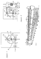
- Figure 1 shows the machine provided with equipment for bending irons (B), provided with a roller (C) that is inclined with respect to the coil (X) plane and inclined downward, that causes the lateral bending of the iron and directs the coil (X) itself toward the idle upper roller (D), that realizes the spiral diameter.
- the mobile idle upper roller (D) can be moved manually or electromechanically, it can also move upward or downward to vary the diameter and parallely to the bending plane to conform with the coil (X) pitch.
- the two front cylinders (E) support the spiral (X) in its formation and they both rotate in the same direction to help the feed of the forming spiral (X).
- Figure 2 shows an axonometric view of the machine, in which it is possible to notice the parallel cylinders (E), that support the spiral (X) for its whole length; at one end of the cylinders (E) there is the bending equipment (B).
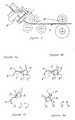
- Figure 3 shows the bending unit of the machine, in case a very long-pitched spiral must be realized; it is possible to notice the bending rollers (B), the inclined roller (C) coupled with a second series of rollers (M), where the iron (X) is bent laterally.
- Figures 4a, 4b, 4c, 4d show in detail the movement of one overturning scythe-shaped part (N), equipped with hook (G), that rests on and then grasps one bar (L) of the metal structure (R), resting on the parallel cylinders (E) and that rotating around the pivot (Q) raises and extracts the metal structure (R) from the machine.
- Each hook (G) is provided with a catch that hinders the sliding of the structure along the hook (G) itself; besides, a tooth near the pivot (P) of each hook (G) doesn't allow the hook (G) itself to rotate in the direction opposite to that of the structure (R) lifting, past the approximately aligned position of the hook (G) with the scythe-shaped metal part (N).
- the upper part of the positioning forks (Fp) is rhomboid-shaped, with an upper vertical notch slightly wider than a longitudinal bar (B).
- these positioning forks (Fp) are raised, due to their form they take a single bar (B) from the group of longitudinal bars (B) to be welded and they raise it until the upper point inside the spiral (S), and then it has to be welded.
- a shear for example, an electropneumatic shear (A) is placed at the exit of the iron from the bending cylinders (B); it is controlled by an electromechanism connected with the machine, that provides for cutting the iron of the spiral (S), thus separating the spiral itself (S).
- a shear for example, an electropneumatic shear (A)
- A is placed at the exit of the iron from the bending cylinders (B); it is controlled by an electromechanism connected with the machine, that provides for cutting the iron of the spiral (S), thus separating the spiral itself (S).
- the feelers (T) and the torch (Z) of the welding machine are mounted on this trolley (I); on the edge of the trolley (I) there is also the welding machine (U).
- the feelers (T) that can be of any kind, preferably consist of a stem equipped with an electric contact that passes near the longitudinal bar (L) to be welded.
- the trolley provides for positioning the feeler (T) near this longitudinal bar (L) and for dragging it for the whole length of the bar itself.
- the torch (Z) is retracted and/or rotated and the trolley (I) is set into motion again until when the feeler (T) doesn't find another contact point between the bar (L) and the spiral (S).
Landscapes
- Engineering & Computer Science (AREA)
- Mechanical Engineering (AREA)
- Wire Processing (AREA)
- Iron Core Of Rotating Electric Machines (AREA)
- Reinforcement Elements For Buildings (AREA)
- Piles And Underground Anchors (AREA)
- Diaphragms For Electromechanical Transducers (AREA)
- Springs (AREA)
Claims (9)
- Procédé pour la fabrication d'armatures métalliques (R) en forme de spirales comprenant les opérations suivantes : former un enroulement (X) et fixer un certain nombre de barres d'armature longitudinales (L) sur l'intérieur de l'enroulement, caractérisé par le support dudit nombre de barres longitudinales d'armature (L) proches l'une de l'autre, former l'enroulement, tout en le faisant tourner, de manière que l'enroulement se développe autour des barres longitudinales supportées, après formation de l'enroulement, arrêter sa rotation et déplacer successivement les barres longitudinales d'armature (L) contre l'intérieur de l'enroulement, puis fixer ces barres (L) à l'enroulement (X) au moyen d'une machine de fixation (U) qui est mobile dans la direction longitudinale de l'enroulement.
- Machine pour la production d'armatures métalliques (R) en forme de spirales, comprenant un équipement de cintrage pour former un enroulement comprenant une série de rouleaux de cintrage (B), et au moins un, rouleau successif (C) incliné et déplacé par rapport au plan des rouleaux de cintrage (B), une série de fourchettes, mobiles verticalement (F), placées dans une direction longitudinale et équipées de moyens supports pour supporter les barres longitudinales d'armature (L), cet équipement de cintrage étant agencé en poste fixe de manière que le plan des rouleaux de cintrage soit perpendiculaire à la direction longitudinale, comprenant encore des moyens pour faire tourner et supporter l'enroulement (S), de manière que l'enroulement pendant sa formation se développe autour des barres longitudinales (L), et des moyens (u) pour fixer individuellement les barres d'armature sur l'intérieur de l'enroulement, lesquelles sont mobiles dans la direction longitudinale de l'enroulement.
- Machine selon la revendication 2, comprenant des fourchettes de positionnement mobiles verticalement (Fp) ayant un siège supérieur apte à loger une barre longitudinale d'armature (L), et dans laquelle ces fourchettes (Fp), lorsqu'elles sont surélevées, soulèvent une seule barre longitudinale (L) au moyen du siège supérieur et l'amènent à proximité de la partie supérieure de la spirale (S) sur la face intérieure de cette dernière.
- Machine selon la revendication 3, comprenant au moins une machine de soudage (U) mobile au moyen d'actionneurs électromécaniques ou électropneumatiques, et au moins un palpeur (T) monté sur un chariot (T), mobile parallèlement aux barres longitudinales (T), ledit palpeur (T) étant capable de détecter le point de contact entre la spirale (S) et la barre longitudinale (T) soulevée par les fourchettes de positionnement (Fp), et capable de faire fonctionner directement ou par l'intermédiaire d'un circuit électrique/électronique ou de tout autre moyen, la machine de soudage (U) qui est amenée près du point de contact entre la spirale (S) et les barres (T) et effectue le soudage.
- Machine selon l'une quelconque des revendications 2 à 4, comprenant une seconde unité de cintrage (M) ayant trois rouleaux définissant une direction de cintrage qui n'est pas parallèle à celle de l'unité principale de cintrage (B), de sorte qu'elle est capable d'effectuer des spirales à très long pas, et dans laquelle la position de la seconde unité de cintrage (M) peut être modifiée à la main ou par un procédé électromécanique.
- machine selon l'une quelconque des revendications 2 à 5, comprenant un rouleau supérieur (D) placé au-dessus des rouleaux de cintrage (B) pour former le diamètre et le pas de la spirale (S), et dans laquelle ce rouleau supérieur (D) peut être déplacé à la main et/ou mécaniquement pour faire varier le pas et le diamètre de la spirale (S).
- Machine selon l'une quelconque des revendications 2 à 6, comprenant deux cylindres parallèles (E) perpendiculaires au plan des rouleaux de cintrage (B), de manière à supporter la spirale (S) pendant sa formation, lesdits cylindres (E) étant capables de tourner autour de leur axe dans le même sens, afin de faciliter l'avance de la spirale (S) en cours de fabrication.
- Machine selon l'une quelconque des revendications 2 à 7, comprenant une série de pièces métalliques (N) de retournement en forme de faucilles, équipées de crochets (G) et placées à côté d'un des cylindres parallèles (E) pour extraire l'armature finie (R), et dans laquelle ces crochets (G) sont équipés de crampons qui bloquent le glissement de l'armature (R) le long du crochet (G) lui-même, et avec des dents proches du pivot du crochet pour bloquer le crochet (G) en l'empêchant de tourner dans le sens opposé au sens de soulèvement de l'armature au-delà de la position du crochet (G) sensiblement alignée avec la pièce en forme de faucille (N).
- Machine selon l'une quelconque des revendications 2 à 8, comprenant une cisaille (A) qui sectionne automatiquement la spirale (S) lorsque cette dernière a atteint la longueur nécessaire.
Applications Claiming Priority (4)
| Application Number | Priority Date | Filing Date | Title |
|---|---|---|---|
| ITPD910155A IT1257979B (it) | 1991-09-11 | 1991-09-11 | Macchina per la realizzazione di armature in ferro a spirale cilindriche e/o coniche per pali o pilastri di fondazione |
| ITPD910155 | 1991-09-11 | ||
| ITPD920115 | 1992-06-26 | ||
| IT92PD000115A IT1278427B1 (it) | 1992-06-26 | 1992-06-26 | Macchina per la realizzazione di armature in ferro a spirale con posizionamento e saldature automatiche |
Publications (2)
| Publication Number | Publication Date |
|---|---|
| EP0532018A1 EP0532018A1 (fr) | 1993-03-17 |
| EP0532018B1 true EP0532018B1 (fr) | 1997-12-03 |
Family
ID=26331777
Family Applications (1)
| Application Number | Title | Priority Date | Filing Date |
|---|---|---|---|
| EP92115554A Expired - Lifetime EP0532018B1 (fr) | 1991-09-11 | 1992-09-11 | Machine et procédé pour la fabrication des armatures métalliques cylindriques ou coniques en forme de spirale |
Country Status (6)
| Country | Link |
|---|---|
| EP (1) | EP0532018B1 (fr) |
| AT (1) | ATE160712T1 (fr) |
| DE (1) | DE69223360T2 (fr) |
| DK (1) | DK0532018T3 (fr) |
| ES (1) | ES2109968T3 (fr) |
| GR (1) | GR3026234T3 (fr) |
Families Citing this family (5)
| Publication number | Priority date | Publication date | Assignee | Title |
|---|---|---|---|---|
| GB9909755D0 (en) * | 1999-04-29 | 1999-06-23 | Rom Limited | Helical winding machine |
| ITUD20010055A1 (it) * | 2001-03-19 | 2002-09-19 | Piegatrici Macch Elettr | Dispositivo e procedimento per il completamento di gabbie di armatura |
| WO2006119595A1 (fr) | 2005-05-10 | 2006-11-16 | Maria Helena Vieira Maccaferri | Systeme en ligne de decoupe et de cintrage de barres, tiges et rouleaux en acier pour la fabrication d’etriers et de fermes longitudinales, et assemblage d’armatures en acier pour poutres, piliers, semelles, blocs, pieux, tambours et autres elements structuraux en beton arme |
| CN107584053B (zh) * | 2017-09-06 | 2023-05-02 | 中国建筑第八工程局有限公司 | 半自动钢筋笼箍筋安装装置 |
| CN112958724B (zh) * | 2021-03-03 | 2022-07-29 | 中国十七冶集团有限公司 | 一种非标箍筋简易弯制方法 |
Family Cites Families (5)
| Publication number | Priority date | Publication date | Assignee | Title |
|---|---|---|---|---|
| US2903553A (en) * | 1958-02-03 | 1959-09-08 | American Pipe & Constr Co | Continuous cage-making machine |
| CH481339A (de) * | 1968-08-16 | 1969-11-15 | Halmstads Jarnverks Ab | Bewehrungseinheit für Betonrohre, Verfahren zu ihrer Herstellung und Vorrichtung zur Durchführung dieses Verfahrens |
| US3726461A (en) * | 1969-01-29 | 1973-04-10 | Nippon Concrete Ind Co Ltd | Apparatus for forming pc concrete pipe reinforcing |
| FR2123116A1 (fr) * | 1971-01-08 | 1972-09-08 | Commissariat Energie Atomique | Machine cintreuse-spiraleuse pour la fabrication de serpentins en tube ou fil metallique |
| US3875977A (en) * | 1973-03-23 | 1975-04-08 | Universal Oil Prod Co | Method for making cylindrical screens |
-
1992
- 1992-09-11 DE DE69223360T patent/DE69223360T2/de not_active Expired - Lifetime
- 1992-09-11 EP EP92115554A patent/EP0532018B1/fr not_active Expired - Lifetime
- 1992-09-11 ES ES92115554T patent/ES2109968T3/es not_active Expired - Lifetime
- 1992-09-11 DK DK92115554T patent/DK0532018T3/da active
- 1992-09-11 AT AT92115554T patent/ATE160712T1/de active
-
1998
- 1998-02-25 GR GR980400414T patent/GR3026234T3/el unknown
Also Published As
| Publication number | Publication date |
|---|---|
| EP0532018A1 (fr) | 1993-03-17 |
| GR3026234T3 (en) | 1998-05-29 |
| DE69223360T2 (de) | 1998-03-26 |
| ES2109968T3 (es) | 1998-02-01 |
| DK0532018T3 (da) | 1998-08-10 |
| DE69223360D1 (de) | 1998-01-15 |
| ATE160712T1 (de) | 1997-12-15 |
Similar Documents
| Publication | Publication Date | Title |
|---|---|---|
| CN110449540B (zh) | 一种钢筋笼焊接成型机 | |
| US7100642B2 (en) | Machine for the formation of metal mesh and relative method | |
| JP2587905B2 (ja) | 鉄筋籠製造装置 | |
| CN216212862U (zh) | 电感自动绕线机 | |
| JPH07252942A (ja) | 鉄筋コンクリート用金属フレーム及び該金属フレームを形成するための方法とその装置 | |
| EP0791416A1 (fr) | Procédé et dispositif pour la fabrication de cages métalliques pour béton armé | |
| EP0532018B1 (fr) | Machine et procédé pour la fabrication des armatures métalliques cylindriques ou coniques en forme de spirale | |
| DE60019405T2 (de) | Vorrichtung und Verfahren zur Herstellung von Hohlschäften | |
| CN113903594A (zh) | 电感自动绕线机及应用于该绕线机的十字绕线方法 | |
| EP1378302B1 (fr) | Méthode et dispositif de fabrication des cages d'armature | |
| CN115210012B (zh) | 一种用于建筑钢网的弯曲头 | |
| KR900000317B1 (ko) | 조립식 건축부재용 입체철망구조물 제작방법과 그 장치 | |
| US4228335A (en) | Machine for producing reinforcements, in particular for reinforced concrete, and the reinforcements produced thereby | |
| SU1804363A3 (ru) | Способ изготовления двухслойных, изогнутых в форме дуги сварных решетчатых каркасов и установка для его осуществления | |
| KR100419649B1 (ko) | 텐션릴 슬리브 인입장치 | |
| KR20060034483A (ko) | 콘크리트 수로관용 용접철망의 소켓 제조장치 | |
| JPH02197337A (ja) | 組立鉄筋の折り曲げ装置 | |
| EP0841110A2 (fr) | Machine d'assemblage d'armatures pour pieux de fondation | |
| CN113682880A (zh) | Wic超导线材编织机用收线自动换向装置及其控制方法 | |
| CA1260805A (fr) | Filiere d'etirage pour la fabrication de fil metallique | |
| DE4030623C2 (de) | Vorrichtung zum Zuführen von Fadenzuführspulen an einem Spulautomaten | |
| JP2004515360A (ja) | 鉄筋ケージ形成装置および鉄筋ケージ形成方法 | |
| JPS5966940A (ja) | 鉄筋篭の取出し装置 | |
| CN223185808U (zh) | 箍筋自动成型码放焊接设备及盾构管片钢筋笼生产系统 | |
| JPH0368525B2 (fr) |
Legal Events
| Date | Code | Title | Description |
|---|---|---|---|
| PUAI | Public reference made under article 153(3) epc to a published international application that has entered the european phase |
Free format text: ORIGINAL CODE: 0009012 |
|
| AK | Designated contracting states |
Kind code of ref document: A1 Designated state(s): AT BE CH DE DK ES FR GB GR LI LU NL PT SE |
|
| 17P | Request for examination filed |
Effective date: 19930917 |
|
| RAP1 | Party data changed (applicant data changed or rights of an application transferred) |
Owner name: HIGHSTONE VENTURE CAPITAL N.V. |
|
| 17Q | First examination report despatched |
Effective date: 19940805 |
|
| GRAG | Despatch of communication of intention to grant |
Free format text: ORIGINAL CODE: EPIDOS AGRA |
|
| GRAH | Despatch of communication of intention to grant a patent |
Free format text: ORIGINAL CODE: EPIDOS IGRA |
|
| GRAH | Despatch of communication of intention to grant a patent |
Free format text: ORIGINAL CODE: EPIDOS IGRA |
|
| GRAA | (expected) grant |
Free format text: ORIGINAL CODE: 0009210 |
|
| AK | Designated contracting states |
Kind code of ref document: B1 Designated state(s): AT BE CH DE DK ES FR GB GR LI LU NL PT SE |
|
| REF | Corresponds to: |
Ref document number: 160712 Country of ref document: AT Date of ref document: 19971215 Kind code of ref document: T |
|
| REG | Reference to a national code |
Ref country code: CH Ref legal event code: NV Representative=s name: ARNOLD & SIEDSMA AG Ref country code: CH Ref legal event code: EP |
|
| REF | Corresponds to: |
Ref document number: 69223360 Country of ref document: DE Date of ref document: 19980115 |
|
| ET | Fr: translation filed | ||
| REG | Reference to a national code |
Ref country code: ES Ref legal event code: FG2A Ref document number: 2109968 Country of ref document: ES Kind code of ref document: T3 |
|
| REG | Reference to a national code |
Ref country code: PT Ref legal event code: SC4A Free format text: AVAILABILITY OF NATIONAL TRANSLATION Effective date: 19980212 |
|
| REG | Reference to a national code |
Ref country code: DK Ref legal event code: T3 |
|
| PLBE | No opposition filed within time limit |
Free format text: ORIGINAL CODE: 0009261 |
|
| 26N | No opposition filed | ||
| REG | Reference to a national code |
Ref country code: GB Ref legal event code: IF02 |
|
| PGFP | Annual fee paid to national office [announced via postgrant information from national office to epo] |
Ref country code: LU Payment date: 20110926 Year of fee payment: 20 Ref country code: CH Payment date: 20110928 Year of fee payment: 20 |
|
| PGFP | Annual fee paid to national office [announced via postgrant information from national office to epo] |
Ref country code: PT Payment date: 20110826 Year of fee payment: 20 Ref country code: DE Payment date: 20110927 Year of fee payment: 20 Ref country code: GR Payment date: 20110928 Year of fee payment: 20 Ref country code: SE Payment date: 20110930 Year of fee payment: 20 Ref country code: AT Payment date: 20110927 Year of fee payment: 20 Ref country code: GB Payment date: 20110929 Year of fee payment: 20 |
|
| PGFP | Annual fee paid to national office [announced via postgrant information from national office to epo] |
Ref country code: NL Payment date: 20111004 Year of fee payment: 20 Ref country code: BE Payment date: 20110929 Year of fee payment: 20 Ref country code: ES Payment date: 20110930 Year of fee payment: 20 Ref country code: DK Payment date: 20110930 Year of fee payment: 20 Ref country code: FR Payment date: 20111010 Year of fee payment: 20 |
|
| REG | Reference to a national code |
Ref country code: DE Ref legal event code: R071 Ref document number: 69223360 Country of ref document: DE |
|
| REG | Reference to a national code |
Ref country code: DE Ref legal event code: R071 Ref document number: 69223360 Country of ref document: DE |
|
| REG | Reference to a national code |
Ref country code: DK Ref legal event code: EUP |
|
| REG | Reference to a national code |
Ref country code: PT Ref legal event code: MM4A Free format text: MAXIMUM VALIDITY LIMIT REACHED Effective date: 20120911 |
|
| REG | Reference to a national code |
Ref country code: NL Ref legal event code: V4 Effective date: 20120911 |
|
| REG | Reference to a national code |
Ref country code: CH Ref legal event code: PL |
|
| BE20 | Be: patent expired |
Owner name: *HIGHSTONE VENTURE CAPITAL N.V. Effective date: 20120911 |
|
| REG | Reference to a national code |
Ref country code: GB Ref legal event code: PE20 Expiry date: 20120910 |
|
| REG | Reference to a national code |
Ref country code: AT Ref legal event code: MK07 Ref document number: 160712 Country of ref document: AT Kind code of ref document: T Effective date: 20120911 |
|
| REG | Reference to a national code |
Ref country code: SE Ref legal event code: EUG |
|
| PG25 | Lapsed in a contracting state [announced via postgrant information from national office to epo] |
Ref country code: GB Free format text: LAPSE BECAUSE OF EXPIRATION OF PROTECTION Effective date: 20120910 Ref country code: DE Free format text: LAPSE BECAUSE OF EXPIRATION OF PROTECTION Effective date: 20120912 |
|
| PG25 | Lapsed in a contracting state [announced via postgrant information from national office to epo] |
Ref country code: PT Free format text: LAPSE BECAUSE OF EXPIRATION OF PROTECTION Effective date: 20120918 |
|
| REG | Reference to a national code |
Ref country code: GR Ref legal event code: MA Ref document number: 980400414 Country of ref document: GR Effective date: 20120912 |
|
| REG | Reference to a national code |
Ref country code: ES Ref legal event code: FD2A Effective date: 20130715 |
|
| PG25 | Lapsed in a contracting state [announced via postgrant information from national office to epo] |
Ref country code: ES Free format text: LAPSE BECAUSE OF EXPIRATION OF PROTECTION Effective date: 20120912 |