EP0533538B1 - Bildverstärkerröhre mit Helligkeitskorrektur - Google Patents
Bildverstärkerröhre mit Helligkeitskorrektur Download PDFInfo
- Publication number
- EP0533538B1 EP0533538B1 EP92402488A EP92402488A EP0533538B1 EP 0533538 B1 EP0533538 B1 EP 0533538B1 EP 92402488 A EP92402488 A EP 92402488A EP 92402488 A EP92402488 A EP 92402488A EP 0533538 B1 EP0533538 B1 EP 0533538B1
- Authority
- EP
- European Patent Office
- Prior art keywords
- image intensifier
- intensifier tube
- attenuating element
- attenuating
- tube
- Prior art date
- Legal status (The legal status is an assumption and is not a legal conclusion. Google has not performed a legal analysis and makes no representation as to the accuracy of the status listed.)
- Expired - Lifetime
Links
- 230000003287 optical effect Effects 0.000 claims description 11
- 230000000295 complement effect Effects 0.000 claims description 3
- 239000011521 glass Substances 0.000 description 8
- 230000002745 absorbent Effects 0.000 description 3
- 239000002250 absorbent Substances 0.000 description 3
- 230000005540 biological transmission Effects 0.000 description 3
- 230000007423 decrease Effects 0.000 description 3
- OAICVXFJPJFONN-UHFFFAOYSA-N Phosphorus Chemical compound [P] OAICVXFJPJFONN-UHFFFAOYSA-N 0.000 description 2
- 239000000853 adhesive Substances 0.000 description 2
- 230000001070 adhesive effect Effects 0.000 description 2
- 230000002238 attenuated effect Effects 0.000 description 2
- 238000009826 distribution Methods 0.000 description 2
- 239000003292 glue Substances 0.000 description 2
- 230000000149 penetrating effect Effects 0.000 description 2
- 239000012780 transparent material Substances 0.000 description 2
- 229920000297 Rayon Polymers 0.000 description 1
- 241001639412 Verres Species 0.000 description 1
- 238000004026 adhesive bonding Methods 0.000 description 1
- 238000013459 approach Methods 0.000 description 1
- 230000007547 defect Effects 0.000 description 1
- 230000000593 degrading effect Effects 0.000 description 1
- 230000000694 effects Effects 0.000 description 1
- 238000009776 industrial production Methods 0.000 description 1
- 239000000463 material Substances 0.000 description 1
- 238000000034 method Methods 0.000 description 1
- 230000007935 neutral effect Effects 0.000 description 1
- 230000005855 radiation Effects 0.000 description 1
- 239000002964 rayon Substances 0.000 description 1
- 230000000284 resting effect Effects 0.000 description 1
Images

Classifications
-
- H—ELECTRICITY
- H01—ELECTRIC ELEMENTS
- H01J—ELECTRIC DISCHARGE TUBES OR DISCHARGE LAMPS
- H01J31/00—Cathode ray tubes; Electron beam tubes
- H01J31/08—Cathode ray tubes; Electron beam tubes having a screen on or from which an image or pattern is formed, picked up, converted, or stored
- H01J31/50—Image-conversion or image-amplification tubes, i.e. having optical, X-ray, or analogous input, and optical output
- H01J31/501—Image-conversion or image-amplification tubes, i.e. having optical, X-ray, or analogous input, and optical output with an electrostatic electron optic system
-
- H—ELECTRICITY
- H01—ELECTRIC ELEMENTS
- H01J—ELECTRIC DISCHARGE TUBES OR DISCHARGE LAMPS
- H01J29/00—Details of cathode-ray tubes or of electron-beam tubes of the types covered by group H01J31/00
- H01J29/86—Vessels; Containers; Vacuum locks
- H01J29/89—Optical or photographic arrangements structurally combined or co-operating with the vessel
Definitions
- the invention relates to image intensifier tubes, in particular of the radiological type. It particularly relates to optical means making it possible to correct the distribution of the light intensity at the output of the image intensifier tube.
- Image intensifier tubes are vacuum tubes comprising an input screen, located at the front of the tube, an electronic optical system, and a visible image observation screen located at the rear of the tube, on the side of an exit window of the latter.
- the input screen further includes a scintillator screen which converts the incident x photons into visible photons.
- Visible photons excite a photocathode which in response generates a flow of electrons.
- This flow of electrons is then transmitted by the electronic optical system which focuses the electrons, and directs them on the observation screen, more precisely on a cathodoluminescent screen generally constituted by one or more layers of luminophoric grains; the cathodoluminescent screen then emits visible light.
- Figure 1 schematically shows such an image intensifier tube of the radiological type.
- the intensifier tube 1 comprises a glass envelope 2, one end of which, at the front of the tube, is closed by an entry window 3 exposed to x-ray photon radiation.
- the second end of the envelope forming the rear of the tube is closed by an exit window 4 transparent to light.
- the x-rays are converted into light rays by a scintillator screen 5.
- the light rays excite a photocathode 6 which in response produces electrons.
- These electrons are extracted from photocathode 5 accelerated towards the exit window 4 using different electrodes 7, and an anode 8 arranged along a longitudinal axis 9 of the tube and which form the electronic optical system.
- the outlet window 4 is formed by a transparent piece of glass attached in a sealed manner to the envelope 2.
- This piece of glass furthermore constitutes, in the example shown, a support which carries a cathodoluminescent screen 10, made of phosphors for example.
- the impact of the electrons on the cathodoluminescent screen 10 makes it possible to reconstitute an image (amplified in luminance) which initially was formed on the surface of the photocathode 6.
- the exit window 4 made of glass forms part of the envelope 2, in such a way that an outside face 13 of this window, opposite to the phosphor layer 10, constitutes an outside part of the tube 1.
- the image displayed by the lumiminophore layer 10 is visible through the glass piece which constitutes the exit window 4.
- optical sensor devices (not shown) are arranged outside the tube near the exit window 4 to capture this image through it and allow its observation.
- the intensifier tube 1 may further include, as in the example shown, a transparent blade 14 secured by a layer of adhesive 15 to the outer face 13 of the outlet window 4.
- the function of the transparent blade 14 is to improve the contrast, and for this purpose it includes a significant thickness E 10 mm for example.
- the surface of the input screen that is to say the surfaces of the input window 3 as well as of the scintillator and of the photocathode 5, 6 are not flat but curved.
- the electronic density generated by the entry screen is not uniform, and this is reflected at the exit of the tube on the brightness curve, along a diameter D of the exit window 4: the brightness curve represents the light intensity at each point of the diameter D of the exit window 4.
- this curve is generally in the shape of an arc of a circle: the brightness is maximum towards the center, and decreases markedly as one approaches the edges.
- the decrease in gloss at the edges relative to the center is commonly between 25% and 30%, and can reach 35% for intensifier tubes having large entry windows.
- One of the aims of the invention is to improve the brightness curve of an image intensifier tube by reducing the difference between the center and the edges, in a simpler way and more compatible with industrial requirements, without degrading the other characteristics.
- the correction of the brightness curve is accomplished at the exit window, using a light attenuator interposed on the path of the light rays emitted by the cathodoluminescent screen in the direction from the outside of the intensifier tube, and by giving this attenuator a non-uniform opacity which achieves the desired compensation.
- an image intensifier tube comprising an outlet window, a cathodoluminescent screen providing a visible image outside said intensifier tube through the outlet window, is characterized in that it further comprises a light attenuation device disposed facing the exit window and, have a greater opacity to light facing a central area of the exit window than towards the edges of the latter.
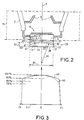
- FIG. 2 is an enlarged view of a box 19 in FIG. 1, in order to more particularly represent the outlet window 4 of an image intensifier tube.
- the tube 1 has an outlet window 4 carrying, inside the tube, the cathodoluminescent layer 10, in the same manner as in the example of FIG. 1.
- the exit window 4 carries on its face 13, opposite the cathodoluminescent screen 10, a light attenuating device 20 whose opacity to light varies between its edges 21 and its center O; the center O being located on the longitudinal axis 9 of the tube, it also corresponds to the center of the outlet window 4.
- the attenuating device comprises an attenuating element 25 made of a semi-transparent material.
- the thickness of the attenuating element 25 varies, from a large thickness EF in the region of the center O, to a reduced thickness ER on the edges 21 of this attenuating element.
- the attenuating element 25 is produced, for example, from mass-tinted glass (neutral tint for example), a material which is commonly found on the market with different light transmission values which can be for example between 50% and 80%.
- the attenuating element 25 has the general shape of a lens of the plano-convex type.
- the compensation provided on the gloss curve by the attenuating element 25 is all the greater the greater the thickness at the center O and weak at the edges 21.
- the edges 21 can have a non-negligible thickness ER with respect to the large thickness EF of the center O, as shown in the example of FIG. 2.
- FIG. 3 shows a brightness curve 40 in solid lines obtained at the output of an image intensifier tube, along the diameter of the outlet window 4 and more precisely along the diameter D1 of the attenuating element 25, with the conditions above mentioned.
- the diameter D1 has been plotted on the abscissa and the brightness measured, of course, with the attenuating device 25 interposed on the ordinate.
- the curve 40 shows a maximum of brightness towards the center O and a fairly pronounced decrease towards the edges 21; with a zero value before the edges 21, which shows that the diameter D1 of the attenuating element 25 is a little larger than the diameter of the useful field at the outlet of the tube 1.
- the curve has the shape of an arc of a circle flattened towards the center O.
- the attenuating element the attenuation coefficient and the profile which would make it possible to obtain a substantially straight curve and horizontal, or even overcompensation to take into account in some cases the requirements of optical sensor devices intended to observe the image.
- the attenuation device constitutes an optical doublet with parallel faces 28, 29: it consists of two complementary parts 25, 27 of which the first is the element attenuator 25, in the form of plano-convex lenses, and the second of which is complementary to the first, that is to say of plano-concave shape, and constitutes a cradle 27 at the convex part 30 of the attenuating element 25 ; of course the cradle 27 is transparent to light.
- the two faces 28, 29 are mutually parallel and parallel to the planes of the outlet window 4 and of the cathodoluminescent screen 10.
- the attenuating element 25 can also be directly secured to the outlet window 4 by gluing, for example.
- the simplest and most natural way of attaching the attenuating element 25 to the exit window is not the most suitable.
- the simplest way to fix the attenuating element 25 to the window 4 consists in placing it on the latter with the flat face 28 of this attenuating element 25 resting on the outlet window, that is to say say directed towards the cathodoluminescent screen 10.
- the attenuating element 4 is fixed with the opposite orientation, that is to say with its convex part 30 oriented towards the exit window 4 and therefore towards the cathodoluminescent screen 10, for reasons explained below, this as well in the case where the attenuating element 25 is mounted in an optical doublet as in the case where it is mounted directly on the outlet window 4.
- the space occupied by the cradle 27 shown in Figure 2 is filled with glue; commercially available adhesives are transparent to light and have various indices of refraction which can therefore be chosen to be very close to the indices of the transparent materials used.
- the attenuating element 25 corrects the gloss curve at the outlet of the tube in the same way for one or the other of the two possible orientations defined above.
- the presence of the attenuating element 25 provides an additional advantageous effect, which is manifested by a strong improvement in contrast.
- This improvement in contrast results from the fact that, by mounting an element on the exit window 4 which reduces light transmission, the rays parallel to the plane of the exit window are attenuated less, that is to say parallel to the longitudinal axis 9, and the inclined rays are more attenuated because they cross a greater absorbent length; the inclined rays being those which degrade the contrast.
- the attenuating element is mounted with its convex part 30 oriented towards the outlet window 4, as shown in FIG. 2, and as it is recommended to do, the attenuation due to the absorbent length crossed L a (in l the attenuating element) is the same for radii r1, r2 inclined by the same angle value a1 and penetrating into the attenuating element 25 at the same point B, but with different directions.
- the attenuating element 25 is mounted with the opposite orientation (not shown), that is to say with its planar face 26 bearing on the outlet window 4, for inclined radii such as r1, r2 penetrating into the attenuator 25 at the same point on its flat face 26, the absorbent lengths are different ; which leads to a variable attenuation of the inclined rays as a function of their direction.
- the correction of the brightness curve in accordance with the invention can be applied in substantially the same way to all types of image intensifier tubes, with scintillator screen or not, because the attenuating element 25 which achieves this correction, can be mounted outside the intensifier tube. Therefore, another important advantage is that the intensifier tube and the attenuating element 25 can be constructed independently of each other. An attenuator element 25 already mounted can thus possibly be replaced by another carrying out a different correction, and this without damage to the intensifier tube.
Landscapes
- Image-Pickup Tubes, Image-Amplification Tubes, And Storage Tubes (AREA)
Claims (10)
- Bildverstärkerröhre mit einem Ausgangsfenster (4), einem Kathodolumineszenzschirm (10), der durch das Ausgangsfenster hindurch außerhalb der Bildverstärkerröhre (1) ein sichtbares Bild liefert, dadurch gekennzeichnet, daß sie ferner eine Vorrichtung (20) zum Dämpfen der Lichtintensität aufweist, die in Ausrichtung auf das Ausgangsfenster (4) angeordnet ist und im Bereich einer Mittelzone (O) eine größere Opazität für das Licht als zu den Rändern (21) des Ausgangsfensters (4) hin aufweist.
- Verstärkerröhre nach Anspruch 1, dadurch gekennzeichnet, daß die Dämpfungsvorrichtung (20) ein Dämpfungselement (25) enthält, dessen Opazität für das Licht mit seiner Dicke (EF, ER) zunimmt.
- Verstärkerröhre nach Anspruch 2, dadurch gekennzeichnet, daß das Dämpfungselement (25) bei seiner Mitte (O) eine größere Dicke (EF) als zu seinen Rändern (21) hin aufweist.
- Verstärkerröhre nach Anspruch 3, dadurch gekennzeichnet, daß das Dämpfungselement (25) die allgemeine Form einer plan-konvexen Linse hat.
- Verstärkerröhre nach einem der Ansprüche 2 oder 3 oder 4, dadurch gekennzeichnet, daß das Dämpfungselement (25) eine ebene Fläche (28) aufweist und daß seine Dicke (EF, ER) sich in bezug auf diese ebene Fläche ändert.
- Verstärkerröhre nach Anspruch 5, dadurch gekennzeichnet, daß die ebene Fläche (28) des Dämpfungselements (25) entgegengesetzt zum Kathodolumineszenzschirm (10) gerichtet ist.
- Verstärkerröhre nach einem der vorhergehenden Ansprüche, dadurch gekennzeichnet, daß die Dämpfungsvorrichtung (20) am Ausgangsfenster (4) außerhalb der Verstärkerröhre befestigt ist.
- Verstärkerröhre nach einem der Ansprüche 2 bis 6, dadurch gekennzeichnet, daß das Dämpfungselement (25) durch Kleben am Ausgangsfenster (4) befestigt ist.
- Verstärkerröhre nach einem der Ansprüche 2 bis 7, dadurch gekennzeichnet, daß die Dämpfungsvorrichtung (20) ferner ein für Licht durchlässiges Teil (27) enthält, dessen Form komplementär zu der des Dämpfungselements (25) ist, damit sie mit letzterem eine Doppeloptik mit parallelen Flächen (28, 29) bildet.
- Bildverstärkerröhre nach einem der vorhergehenden Ansprüche, dadurch gekennzeichnet, daß sie eine Röhre vom Röntgentyp ist.
Applications Claiming Priority (2)
| Application Number | Priority Date | Filing Date | Title |
|---|---|---|---|
| FR9111608A FR2681727B1 (fr) | 1991-09-20 | 1991-09-20 | Tube intensificateur d'image a correction de brillance. |
| FR9111608 | 1991-09-20 |
Publications (2)
| Publication Number | Publication Date |
|---|---|
| EP0533538A1 EP0533538A1 (de) | 1993-03-24 |
| EP0533538B1 true EP0533538B1 (de) | 1994-07-13 |
Family
ID=9417137
Family Applications (1)
| Application Number | Title | Priority Date | Filing Date |
|---|---|---|---|
| EP92402488A Expired - Lifetime EP0533538B1 (de) | 1991-09-20 | 1992-09-11 | Bildverstärkerröhre mit Helligkeitskorrektur |
Country Status (5)
| Country | Link |
|---|---|
| US (1) | US5248874A (de) |
| EP (1) | EP0533538B1 (de) |
| JP (1) | JPH05205693A (de) |
| DE (1) | DE69200238T2 (de) |
| FR (1) | FR2681727B1 (de) |
Families Citing this family (4)
| Publication number | Priority date | Publication date | Assignee | Title |
|---|---|---|---|---|
| US5519208A (en) * | 1994-09-29 | 1996-05-21 | Esparza; Joel | Infrared aided method and apparatus for venous examination |
| FR2758002B1 (fr) * | 1996-12-27 | 2004-07-02 | Thomson Tubes Electroniques | Systeme de visualisation avec ecran d'observation luminescent |
| US6069352A (en) * | 1997-09-09 | 2000-05-30 | Interscience, Inc. | Intensity control system for intensified imaging systems |
| GB9820655D0 (en) | 1998-09-22 | 1998-11-18 | British Telecomm | Packet transmission |
Family Cites Families (12)
| Publication number | Priority date | Publication date | Assignee | Title |
|---|---|---|---|---|
| BE467895A (de) * | 1945-07-09 | |||
| US3443104A (en) * | 1966-02-17 | 1969-05-06 | Rauland Corp | Image intensifier tube with shading compensation |
| US4069121A (en) * | 1975-06-27 | 1978-01-17 | Thomson-Csf | Method for producing microscopic passages in a semiconductor body for electron-multiplication applications |
| FR2318474A1 (fr) * | 1975-07-17 | 1977-02-11 | Thomson Csf | Dispositif d'affichage par electrophorese |
| DE2808043C3 (de) * | 1978-02-24 | 1981-10-22 | Optische Werke G. Rodenstock, 8000 München | Optisches Systems für Nachsichtbrillen |
| FR2492160A1 (fr) * | 1980-10-14 | 1982-04-16 | Thomson Csf | Cible pyroelectrique et tube de prise de vues muni d'une telle cible |
| JPS61185852A (ja) * | 1985-02-12 | 1986-08-19 | Mitsubishi Electric Corp | 陰極線管 |
| JPH0754675B2 (ja) * | 1986-03-31 | 1995-06-07 | 株式会社東芝 | X線イメ−ジインテンシフアイア |
| US4755718A (en) * | 1986-11-26 | 1988-07-05 | The United States Of America As Represented By The Secretary Of The Army | Wide angle and graded acuity intensifier tubes |
| JP2514952B2 (ja) * | 1987-03-13 | 1996-07-10 | 株式会社東芝 | X線イメ−ジ管 |
| FR2629267B1 (fr) * | 1988-03-22 | 1996-01-26 | Thomson Csf | Dispositif de conversion chromatique d'une image obtenue en rayonnement electromagnetique et procede de fabrication correspondant |
| NL8900040A (nl) * | 1989-01-09 | 1990-08-01 | Philips Nv | Roentgenbeeldversterkerbuis met selectief filter. |
-
1991
- 1991-09-20 FR FR9111608A patent/FR2681727B1/fr not_active Expired - Fee Related
-
1992
- 1992-09-04 US US07/941,162 patent/US5248874A/en not_active Expired - Fee Related
- 1992-09-11 DE DE69200238T patent/DE69200238T2/de not_active Expired - Fee Related
- 1992-09-11 EP EP92402488A patent/EP0533538B1/de not_active Expired - Lifetime
- 1992-09-18 JP JP4249636A patent/JPH05205693A/ja active Pending
Also Published As
| Publication number | Publication date |
|---|---|
| FR2681727B1 (fr) | 1993-11-05 |
| US5248874A (en) | 1993-09-28 |
| DE69200238T2 (de) | 1994-11-17 |
| DE69200238D1 (de) | 1994-08-18 |
| FR2681727A1 (fr) | 1993-03-26 |
| EP0533538A1 (de) | 1993-03-24 |
| JPH05205693A (ja) | 1993-08-13 |
Similar Documents
| Publication | Publication Date | Title |
|---|---|---|
| FR2925218A1 (fr) | Tube intensificateur d'image a encombrement reduit et systeme de vision nocturne equipe d'un tel tube | |
| EP2195685A2 (de) | Szintillator für eine bildgebereinrichtung, szintillatormodul, bildgebereinrichtung mit einem solchen szintillator und verfahren zur herstellung eines szintillators | |
| FR2687007A1 (fr) | Tube intensificateur d'image notamment du type a focalisation de proximite. | |
| EP0533538A1 (de) | Bildverstärkerröhre mit Helligkeitskorrektur | |
| EP0474549B1 (de) | Bildverstärkerröhre mit optimierter elektrischer Isolation | |
| FR2608836A1 (fr) | Tube de conversion photoelectrique | |
| EP0187561A1 (de) | Verfahren zur Nutzung einer Lichtstrahlung mittels fluoreszierender optischer Fasern und Vorrichtungen oder Geräte die dieses Verfahren anwenden | |
| EP0319080B1 (de) | Röntgenstrahl-Bildverstärkerröhre | |
| EP0553578B1 (de) | Bildverstärkerröhre mit Intensitätsverteilungkompensation | |
| EP0540092B1 (de) | Bilddetektor mit vermindertem Störlicht und Anwendung auf einen Endsensor | |
| FR2545269A1 (fr) | Ecran electroluminescent et son procede de fabrication | |
| EP0851455B1 (de) | Röntgenbildverstärkerröhre | |
| EP0025374B1 (de) | Wandler nicht-sichbarer in sichtbare Photone und Anlage zur zerstörungsfreien Prüfung unter Verwendung dieses Wandlers | |
| FR2498007A1 (fr) | Dispositif protecteur pour substrat de cathode en verre, son procede de fabrication et tube intensificateur d'images en comportant application | |
| EP0639784B1 (de) | Polarisierender Leuchtkasten | |
| FR2478373A1 (fr) | Tube convertisseur d'image a contraste ameliore notamment pour intensificateurs d'image a rayons x | |
| EP0079651B1 (de) | Photoelektrischer Detektor | |
| EP0670078A1 (de) | Apparat zur bildverstärkung mittels lumineszenz | |
| EP0039103B1 (de) | Gammakamera unter Anwendung einer Szintillationslichtverstärkungseinrichtung | |
| FR2596200A1 (fr) | Tube de generation d'image | |
| EP0155890A2 (de) | Bildwandlerröhre mit Spaltenabtastung | |
| EP0412887A1 (de) | Mit hohem Wirkungsgrad kathodolumineszenter Schirm für hochleuchtende KathodenstrahlrÀ¶hre | |
| EP0013525A1 (de) | Szintillationskamera mit verbessertem räumlichem Auflösungsvermögen | |
| EP0334734A1 (de) | Chromatischer Wandler für elektromagnetische Bilder und sein Herstellungsverfahren | |
| EP0182405A1 (de) | Photoelektrische Vorrichtung zum Nachweisen leuchtender Ereignisse |
Legal Events
| Date | Code | Title | Description |
|---|---|---|---|
| PUAI | Public reference made under article 153(3) epc to a published international application that has entered the european phase |
Free format text: ORIGINAL CODE: 0009012 |
|
| AK | Designated contracting states |
Kind code of ref document: A1 Designated state(s): DE FR NL |
|
| 17P | Request for examination filed |
Effective date: 19930420 |
|
| 17Q | First examination report despatched |
Effective date: 19930604 |
|
| GRAA | (expected) grant |
Free format text: ORIGINAL CODE: 0009210 |
|
| AK | Designated contracting states |
Kind code of ref document: B1 Designated state(s): DE FR NL |
|
| REF | Corresponds to: |
Ref document number: 69200238 Country of ref document: DE Date of ref document: 19940818 |
|
| PLBE | No opposition filed within time limit |
Free format text: ORIGINAL CODE: 0009261 |
|
| STAA | Information on the status of an ep patent application or granted ep patent |
Free format text: STATUS: NO OPPOSITION FILED WITHIN TIME LIMIT |
|
| 26N | No opposition filed | ||
| PGFP | Annual fee paid to national office [announced via postgrant information from national office to epo] |
Ref country code: DE Payment date: 20010821 Year of fee payment: 10 |
|
| PGFP | Annual fee paid to national office [announced via postgrant information from national office to epo] |
Ref country code: NL Payment date: 20010830 Year of fee payment: 10 |
|
| PGFP | Annual fee paid to national office [announced via postgrant information from national office to epo] |
Ref country code: FR Payment date: 20010925 Year of fee payment: 10 |
|
| PG25 | Lapsed in a contracting state [announced via postgrant information from national office to epo] |
Ref country code: NL Free format text: LAPSE BECAUSE OF NON-PAYMENT OF DUE FEES Effective date: 20030401 Ref country code: DE Free format text: LAPSE BECAUSE OF NON-PAYMENT OF DUE FEES Effective date: 20030401 |
|
| PG25 | Lapsed in a contracting state [announced via postgrant information from national office to epo] |
Ref country code: FR Free format text: LAPSE BECAUSE OF NON-PAYMENT OF DUE FEES Effective date: 20030603 |
|
| REG | Reference to a national code |
Ref country code: FR Ref legal event code: ST |