EP0534478B1 - Tragbarer Telefonapparat mit einer elektronischen Notizbuchfunktion - Google Patents
Tragbarer Telefonapparat mit einer elektronischen Notizbuchfunktion Download PDFInfo
- Publication number
- EP0534478B1 EP0534478B1 EP92116493A EP92116493A EP0534478B1 EP 0534478 B1 EP0534478 B1 EP 0534478B1 EP 92116493 A EP92116493 A EP 92116493A EP 92116493 A EP92116493 A EP 92116493A EP 0534478 B1 EP0534478 B1 EP 0534478B1
- Authority
- EP
- European Patent Office
- Prior art keywords
- portable telephone
- data
- openable
- telephone apparatus
- key
- Prior art date
- Legal status (The legal status is an assumption and is not a legal conclusion. Google has not performed a legal analysis and makes no representation as to the accuracy of the status listed.)
- Expired - Lifetime
Links
Images


Classifications
-
- H—ELECTRICITY
- H04—ELECTRIC COMMUNICATION TECHNIQUE
- H04M—TELEPHONIC COMMUNICATION
- H04M1/00—Substation equipment, e.g. for use by subscribers
- H04M1/72—Mobile telephones; Cordless telephones, i.e. devices for establishing wireless links to base stations without route selection
- H04M1/724—User interfaces specially adapted for cordless or mobile telephones
- H04M1/72403—User interfaces specially adapted for cordless or mobile telephones with means for local support of applications that increase the functionality
-
- H—ELECTRICITY
- H04—ELECTRIC COMMUNICATION TECHNIQUE
- H04M—TELEPHONIC COMMUNICATION
- H04M1/00—Substation equipment, e.g. for use by subscribers
-
- H—ELECTRICITY
- H04—ELECTRIC COMMUNICATION TECHNIQUE
- H04M—TELEPHONIC COMMUNICATION
- H04M1/00—Substation equipment, e.g. for use by subscribers
- H04M1/006—Call diverting means
-
- H—ELECTRICITY
- H04—ELECTRIC COMMUNICATION TECHNIQUE
- H04M—TELEPHONIC COMMUNICATION
- H04M1/00—Substation equipment, e.g. for use by subscribers
- H04M1/02—Constructional features of telephone sets
- H04M1/0202—Portable telephone sets, e.g. cordless phones, mobile phones or bar type handsets
- H04M1/0206—Portable telephones comprising a plurality of mechanically joined movable body parts, e.g. hinged housings
- H04M1/0208—Portable telephones comprising a plurality of mechanically joined movable body parts, e.g. hinged housings characterized by the relative motions of the body parts
- H04M1/0214—Foldable telephones, i.e. with body parts pivoting to an open position around an axis parallel to the plane they define in closed position
-
- H—ELECTRICITY
- H04—ELECTRIC COMMUNICATION TECHNIQUE
- H04M—TELEPHONIC COMMUNICATION
- H04M1/00—Substation equipment, e.g. for use by subscribers
- H04M1/02—Constructional features of telephone sets
- H04M1/0202—Portable telephone sets, e.g. cordless phones, mobile phones or bar type handsets
- H04M1/0206—Portable telephones comprising a plurality of mechanically joined movable body parts, e.g. hinged housings
- H04M1/0241—Portable telephones comprising a plurality of mechanically joined movable body parts, e.g. hinged housings using relative motion of the body parts to change the operational status of the telephone set, e.g. switching on/off, answering incoming call
- H04M1/0245—Portable telephones comprising a plurality of mechanically joined movable body parts, e.g. hinged housings using relative motion of the body parts to change the operational status of the telephone set, e.g. switching on/off, answering incoming call using open/close detection
-
- H—ELECTRICITY
- H04—ELECTRIC COMMUNICATION TECHNIQUE
- H04M—TELEPHONIC COMMUNICATION
- H04M1/00—Substation equipment, e.g. for use by subscribers
- H04M1/26—Devices for calling a subscriber
- H04M1/27—Devices whereby a plurality of signals may be stored simultaneously
- H04M1/274—Devices whereby a plurality of signals may be stored simultaneously with provision for storing more than one subscriber number at a time, e.g. using toothed disc
- H04M1/2745—Devices whereby a plurality of signals may be stored simultaneously with provision for storing more than one subscriber number at a time, e.g. using toothed disc using static electronic memories, e.g. chips
- H04M1/27467—Methods of retrieving data
- H04M1/2747—Scrolling on a display
-
- H—ELECTRICITY
- H04—ELECTRIC COMMUNICATION TECHNIQUE
- H04M—TELEPHONIC COMMUNICATION
- H04M1/00—Substation equipment, e.g. for use by subscribers
- H04M1/26—Devices for calling a subscriber
- H04M1/27—Devices whereby a plurality of signals may be stored simultaneously
- H04M1/274—Devices whereby a plurality of signals may be stored simultaneously with provision for storing more than one subscriber number at a time, e.g. using toothed disc
- H04M1/2745—Devices whereby a plurality of signals may be stored simultaneously with provision for storing more than one subscriber number at a time, e.g. using toothed disc using static electronic memories, e.g. chips
- H04M1/275—Devices whereby a plurality of signals may be stored simultaneously with provision for storing more than one subscriber number at a time, e.g. using toothed disc using static electronic memories, e.g. chips implemented by means of portable electronic directories
-
- H—ELECTRICITY
- H04—ELECTRIC COMMUNICATION TECHNIQUE
- H04M—TELEPHONIC COMMUNICATION
- H04M1/00—Substation equipment, e.g. for use by subscribers
- H04M1/64—Automatic arrangements for answering calls; Automatic arrangements for recording messages for absent subscribers; Arrangements for recording conversations
- H04M1/65—Recording arrangements for recording a message from the calling party
- H04M1/6505—Recording arrangements for recording a message from the calling party storing speech in digital form
-
- H—ELECTRICITY
- H04—ELECTRIC COMMUNICATION TECHNIQUE
- H04M—TELEPHONIC COMMUNICATION
- H04M2250/00—Details of telephonic subscriber devices
- H04M2250/14—Details of telephonic subscriber devices including a card reading device
Definitions
- the present invention generally relates to a portable telephone apparatus. More specifically, the present invention is directed to a portable telephone set including an electronic notebook function, as known for example from JP-A-3162025, capable of registering a plurality of telephone directory data. So-called "telephone directory data is constructed of one set of name data and telephone number data.
- the respective numeral keys used to the dialing function must have 4 or more sorts of key functions.
- the numeral key "1" owns 4 different key functions to enter numeral data "1", character data "A", "B” and "C”.
- the above-described conventional portable telephone set is equipped with the data input mode switch for selecting the numeral data input mode and the character data input mode.
- the key for shifting the input digit must be manipulated after the numeral key "1" has been operated three time.
- the conventional portable telephone sets have such a drawback that the key operation must be performed at least four times, depending upon sorts of characters, namely a very cumbersome data input operation is necessarily required.
- the present invention has been made in an attempt to solve the above-described drawback, and therefore, has an object to provide a portable telephone apparatus including an electronic notebook function, capable of simply dialing and also of simply performing data input operation such as telephone directory data entry operation.
- Another object of the present invention is to provide a portable telephone apparatus including an electronic notebook, capable of automatically selecting a telephone mode and an electronic notebook mode.
- a dialing operation is available, whereas in the electronic notebook mode, a data input operation is available.
- a further object of the present invention is to provide a portable telephone apparatus including an electronic notebook function, capable of searching data about the electronic notebook in a telephone mode.
- a portable telephone apparatus equipped with an electronic notebook function is characterized in that a plurality of telephone keys (3) are provided on an outer surface of an openable/closable member (2) mounted on a case body (1) in openable/closable states, and a plurality of electronic notebook keys (4:5) are provided on a rear surface of a the openable/closable n ⁇ member (2) and also a region of front surface of the case body (1), which is covered by the openable/closable member (2).
- Fig. 1 is a front view for indicating an outer view of a portable telephone apparatus according to a first preferred embodiment of the present invention.
- Fig. 2 is a sectional view of the first portable telephone apparatus, taken along a line X-X of Fig. 1.
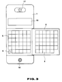
- Fig. 3 is a front view of the first portable telephone apparatus having a member under open condition.
- reference numeral 1 indicates a case body for storing a large number of electronic components which constitute an electronic circuit (will be described later), and reference numeral 2 shows an openable/closable member hinged to the case body 1 at a right edge portion of an upper surface of this case body 1.
- keys 3a, 3b and 3c used to search data about an electronic notebook are furthermore provided on this telephone keyboard 3.
- the first key 3a (“F” key) is to select a sort of electronic notebook data
- the second key 3b (“ ⁇ ” key) is to sequentially select the respective data included in the selected data
- the third key 3c (“ ⁇ ” key) is to successively select the respective data included in the selected data in a direction opposite to that of the above-described " ⁇ " key.
- a keyboard 4 for the electronic notebook is provided at a lower surface of the openable/closable member 2.
- the keyboard for the electronic notebook is also provided on the surface of the case body 1 covered with the openable/closable member 2. Then, a large number of keys required to control the function of the electronic notebook and also to enter data, are provided on the keyboard 4 of the electronic notebook and a keyboard 5 of the electronic notebook mounted on the case body 1 in a separate form. These keys are various control keys, numeral entry keys, character keys and symbol keys.
- the keyboard 4 is provided on the openable/closable member 2.
- a depression button type switch 6 is provided on the case body 1 adjacent the keyboard 5 for the electronic notebook, which is turned ON/OFF when the openable/closable member 2 is opened/closed.
- This switch 6 is to detect to opening/closing states of the openable/closable member 2.
- both of the mode selection control for selecting the telephone function mode and the electronic notebook function mode, and the power supply control for supplying power to the radio communication circuit unit 21 are carried out. More specifically, when the switch 6 is turned ON, namely when the openable/closable member 2 is closed, the telephone function mode is selected so that the display mode is set to the display mode for the telephone and the power is supplied to the radio communication circuit unit 21. Conversely, when the switch 6 is turned OFF, namely when the openable/closable member 2 is opened, the electronic notebook mode is set. Thus, the display mode is set to the display mode for the electronic notebook and the power supply to the radio communication circuit unit 21 is interrupted.
- LSI large-scale integration
- 7 8 and 9 for constructing the radio communication circuit unit, the data memory for the electronic notebook, and the control circuit
- a display unit 10 a microphone 11, a speaker 12 and a circuit board 13 for electrically connecting these electronic components.
- Reference numeral 14 indicates an inner connector for electrically connecting the display unit 10 to a predetermined terminal on the circuit board 13.
- an antenna for receiving a radio (wireless) signal, a sound producing element for a calling purpose, and a power source battery are provided in the case body 1.
- a display window 15 for the display unit 10, a through hole 16 for the microphone 11 and a through hole 17 for the speaker 12 are formed in the upper surface of the case body 1.
- FIG. 4 there is shown a circuit block diagram of an electronic circuit of the first portable telephone apparatus.
- reference numeral 21 shows a radio communication circuit unit (radio telephone circuit unit).
- This radio communication unit 21 is such a circuit for converting an acoustic (audio) signal inputted from the microphone 11 into a radio signal to transmit this radio signal from the antenna 22, and for converting another radio signal received by the antenna 22 into an acoustic signal to supply the acoustic signal to the speaker 12.
- the type of this radio communication circuit arrangement is varied, depending upon the modulating system and the transmitting system. If the digital modulation system is employed and also the TDMA (Time Division Multiplex Access)-TDD (Time Division Duplex) transmitting system is employed, this radio communication circuit unit 21 is so arranged, as shown in Fig.
- an A/D-D/A converting circuit unit 23 converts the analog audio signal derived from the microphone 11 into the digital audio signal and supplies this digital audio signal to the speech coding unit 24. Furthermore, the digital audio signal from the speech coding unit 24 is converted into the analog audio signal and the resultant analog audio signal is sent to the speaker 12 by this A/D-D/A converting circuit 23.
- the speech coding unit 24 compresses the data of the digital audio signal supplied from the A/D-D/A converting circuit unit 23 by the audio coding system with a higher efficiency, and then supplies the compressed digital audio data to the burst mode controller 25. Also, this speech coding unit 24 expands the compressed digital audio data derived from the burst mode controller 25 to the original data length thereof which will be sent to the A/D-D/A converting circuit 23.
- the burst mode controller 25 is such a circuit for performing a synchronization process and a frame process of the transmission/receiving signals based on the TDMA-TDD system.
- This burst mode controller 25 determines a transmission frame (time slot) when the radio communication is established between this first portable telephone apparatus and a radio station (not shown in detail), and also sends the data of the digital audio signal supplied from the speech coding unit 25 and control data (will be discussed later) supplied from a control unit 27 based on the determined transmission frame to the radio transmitter/receiver circuit unit 26.
- the burst mode controller 25 synchronizes the signal transmitted from the radio base station (not shown in detail), which is received in the burst mode by the transmitter/receiver circuit unit 26, decodes the received signal, and sends out a control signal portion contained in this received signal to the control unit 27, and also an audio signal portion contained in this received signal to the speech coding unit 25.
- the function of the transmitter/ receiver circuit unit 26 is to transmit/receive the radio signal digitally modulated between the radio station and the first radio telephone apparatus in accordance with the TDMA-TDD system (method).
- This transmitter/receiver circuit unit26 is arranged by a transmitter circuit for transmitting the digital-modulated radio signal, a receiver circuit for receiving the digital-modulated radio signal so as to demodulate this digital-modulated radio signal, and a frequency synthesizer for changing the frequency of the radio signal when the communication is established between the radio station (not shown in detail) and this first radio telephone apparatus.
- These internal circuits of the radio communication circuit unit 21 are controlled by the above-described control unit 27.
- control unit 27 In response to signals supplied from the above-explained burst mode controller 25, and key input unit 28 containing the above-described three keyboard 3, 4, 5 and switch 6, the control unit 27 is to control the respective circuit units, as described above.
- This control unit 27 includes a microprocessor, a ROM (read-only memory) for previously storing a control program executed by this microprocessor, and a RAM (random access memory) for temporarily storing processed data and the like during the execution of the control program.
- ROM read-only memory
- RAM random access memory
- the respective circuits 23 to 26 for constituting the radio communication circuit unit 21 and the key input unit 28 are connected, and furthermore, an oscillating circuit unit 29 for outputting a reference clock signal, a sound producing unit 30, a RAM (random access memory) 31, a display drive unit 32 coupled to the above-described display unit 10, and a power supply circuit 33 for supply power to the radio communication circuit unit 21 are connected.
- the sound producing unit 30 is such a circuit containing a compact speaker or a sound producing member such as a piezoelectric vibrator.
- the control unit 27 compares the received call number supplied from the burst mode controller 25 of the radio communication circuit unit 21 with the self calling number stored in the ROM, and drives the sound producing unit 30 to produce the sound when a judgement is made that both of these numbers are coincident with each other.
- the RAM 31 is a memory for storing data about the electronic notebook. As represented in Fig. 5, the RAM 31 includes a telephone directory data storage unit TM having a plurality of storage areas; a schedule data storage unit SM, and a memorandum data storage unit MM. Each of these storage areas of the telephone directory data storage unit TM is subdivided to a subarea for storing names and the like, and a subarea for storing telephone numbers, the name and telephone number data which have been entered by the electronic notebook keyboards 4 and 5, are subdivided and thereafter stored into the corresponding subareas.
- each of storage areas of the schedule data storage unit SM are subdivided into a subarea for storing a content of a schedule, a subarea for storing a starting date/time, and a subarea for storing an ending date/time.
- the storage area of the memorandum data storage unit MM is not subdivided, and therefore the data inputted from the electronic notebook keyboards 4 and 5 are stored into this storage area within one memory time. Then, the data stored in these memory units are displayed on the display unit 10 via the control unit 27 and the display drive unit 32 by operating the data searching keys (namely, the above-described keys 3a, 3b and 3c) provided on the telephone keyboard 3, and also the data searching key provided on either the electronic notebook keyboard 4 or 5.
- the display unit 10 is constructed of, for instance, a matrix type liquid crystal display apparatus.
- the display area of this display unit 10 is subdivided into three areas 10a, 10b and 10c as represented in Fig. 6, for example.
- the area 10a corresponds to such an area for displaying the selected function name, mode name, and condition information
- the areas 10b and 10c correspond to areas for displaying the data inputted from the key input unit 28 and the data read out from the RAM 31.
- the mode name "TEL" and a mark indicative of reception sensitivity are displayed in the area 10a.
- the dialing data inputted by manipulating the numeral entry keys of the keyboard 3 are displayed on the area 10c.
- the mode name "TEL. No. SEARCH" is displayed on the area 10a, and also the name portion of the searched date and the telephone number portion thereof are displayed on the area 10b and 10c, respectively.
- the electronic notebook mode indications in the other modes, will be displayed in a similar manner as shown in Fig. 8.
- the power source circuit 33 is to supply power from the power battery 34 to the respective circuit 23 to 26 of the radio communication circuit unit 21.
- a switching circuit employing a switching element, for instance, transistors and the like is provided.
- the control unit 27 turns ON/OFF the above switching circuit in response to the operation signals of the ON/OFF keys employed in the telephone keyboard 3 and the condition signal of the detection switch 6 provided on the case body 1, and also controls the power supply to the radio communication circuit unit 21. Concretely speaking, when the detection switch 6 is brought into the ON-state, namely when the openable/ closable member 2 is closed, the switching circuit is turned ON/OFF every time the ON/OFF key is manipulated.
- the detection switch 6 when the detection switch 6 is brought into the OFF-state, namely when the openable/closable member 2 is opened, the switching circuit is turned OFF without any conditions.
- the power supply to the radio communication circuit unit 21 when the openable/closable member 2 is closed, the power supply to the radio communication circuit unit 21 may be arbitrarily interrupted/commenced by operating the ON/OFF key, whereas when the openable/ closable member 2 is opened, the power supply to the radio communication circuit unit 21 may be automatically interrupted.
- power is supplied from a second power source circuit 35 to other circuit portions than the radio communication circuit unit 21.
- FIG. 9 is a flow chart for representing an operation flow of this portable telephone apparatus with the above-explained key operations.
- Fig. 10 represents key functions of various keys employed on the telephone keyboard 3.
- the process defined at this step S1 is repeatedly executed until the key operation is detected.
- the process operation is advanced to a step S2 at which another check is done whether or not the detection switch 6 is brought into the ON-state. That is, it is judged whether or not the openable/closable member 2 is closed.
- a check is done at a first step S4 as to whether or not the above-described key input operation is performed by operating the key 3a employed in the telephone keyboard 3. If YES (namely, the key 3a is operated), then the process operation is advanced to a step S5 at which the mode changing process is performed. This mode changing process is performed as shown in Fig.
- the telephone directory data search mode is set so that first telephone directory data is displayed on the display unit 10;
- the schedule data search mode is set, whereby first schedule data is displayed on the display unit 10; and
- the normal mode is set so that the reception standby condition is represented, namely the representation shown in Fig. 7 is returned.
- the data representation of the electronic notebook function searched in this telephone mode is different from the search data representation in the electronic notebook mode. For instance, when the searched data corresponds to the telephone directory data, the representation as shown in Fig.
- Fig. 8 is made in the electronic notebook mode, whereas another representation as indicated in Fig. 11 is made in the telephone mode. Then, when an S-key (will be described later) is operated under such a display condition as shown in Fig. 11, in a radio communication line setting process (will be explained later), the telephone number data being displayed is transmitted as dialing data via the burst mode controller 25 of the radio communication circuit unit 21 and the transmitter/receiver circuit unit 26 employed therein to the radio station (not shown in detail).
- the process operation is advanced to a step S6 at which a judgement is made whether the above-described key input operation is carried out by operating the key 3b, or the key 3c. If YES (namely, key 3b or 3c is operated), then the process operation is advanced to a step S7 at which a search process is executed. As shown in Fig. 10, this process is to successively display data while the mode is set to either a telephone directory data search mode, a schedule data search mode. If the mode is set to the normal mode, even when the key 3b and/or the key 3c is manipulated, no process is carried out, but the process operation is returned to the previous step S1.
- the process operation is advanced to a further step S8.
- a check is done whether or not the key input is made by manipulating the ON/Off key.
- the process operation is advanced to a step S9 at which the switching state of the switch circuit in the power source circuit 33 is changed. That is, when the switch circuit is brought into the ON-state, this power supply circuit 33 is turned OFF, whereas when the switch circuit is brought into the OFF-state, the power supply circuit 33 is turned ON. As a result, the power supply to the radio communication circuit unit 21 is controlled and thus the telephone function is ON/OFF controlled.
- step S10 a check is done whether or not the key input operation is performed by manipulating the dialing key (numeral entry key and "#" key). If this key input operation is done by operating the dialing key, the process operation is advanced to a subsequent step S11 at which an input process for the dialing data is performed. As previously stated, the dialing data inputted by operating the numeral entry key is displayed on the area 10c of the display unit 10. Then, the "#" key is used to cancel the inputted dialing data.
- the input dialing data and a cancel signal produced in response to the operations of the "#" key are also transmitted via the burst mode controller 25 and the transmitter/receiver circuit 26 in the radio communication circuit unit 21 to the radio station.
- this "#" key is used to not only cancel the dialing data, but also execute such a process that either the telephone directory data search mode, or the schedule data search mode is returned to the normal mode.
- the process operation is advanced to a further step S12 at which a process for setting a ratio communication line between this first portable telephone apparatus and the radio station is executed.
- the S-key is such a key manipulated when a call is accepted, and a call is transmitted.
- the dialing data is transmitted to the radio station via a radio communication line which has been set subsequent to the establishment of this radio communication line.
- the keyboard to enter the data about the electronic notebook is provided at two different portions of the case body 1, namely the rear surface of the openable/closable member 2 on which upper surface, the telephone keyboard 3 is arranged, and also the region of the case body 1 covered by the openable/ closable member 2, a large quantity of keys are arranged. Furthermore, since a large number of key functions are no longer given to a single key, the simple key operation to enter the data about the electronic notebook can be achieved. Also the switch 6 is employed to detect the open/close state of the openable/closable member 2, so that the state signal of this switch 6 is produced.
- the keys 3a, 3b, 3c for searching the data about the electronic notebook are employed on the telephone keyboard 3 arranged on the upper surface of the openable/closable member 2. Since the telephone directory data and the schedule data can be displayed by manipulating these search keys, a telephone number and a name of a person who will be telephoned can be conformed before a telephone conversation is made. Furthermore, if he wants to have an appointment during the conversation, the operator of this portable telephone apparatus can immediately confirm own schedule. A telephone conversation may be, of course, made with employment of the telephone number of the searched telephone directory data.
- the depression button type switch 6 is mounted on the case body 1 so as to detect the opening/closing state of the openable/closable member 2.
- a depression button type switch but also a pressure sensitive type switch and a light sensitive type switch may be utilized as this detection switch.
- mount this detection switch there is no limitation to mount this detection switch.
- any mounting places of the main body 1 may be selected, depending upon the types of the detection switch.
- this detection switch may be provided on a supporting member for supporting a rotation of the openable/closable member 2, and on this openable/closable member 2.
- the first portable telephone apparatus is so arranged that when the detection is made in response to the state signal of the detection switch 6 that the openable/closable member 2 is opened, the power supply to the radio communication circuit unit is immediately turned ON/OFF.
- a radio telephone system is constructed in such a manner that a telephone transfer service and a voice (audio) storage service are available at a network side, when a detection is established that the openable/closable member 2 is opened in response to the state signal from the detection switch 6, a predetermined signal is transmitted to a radio station at a first stage.
- a transfer demand signal for demanding that a present telephone call is transferred to another telephone set, or a voice storage service demanding signal for demanding that the present telephone call is connected to a voice storage service center is sent out at a first stage, and thereafter the power supply to the radio communication circuit unit 21 is interrupted. It is, of course, possible to control the power supply to the radio communication circuit unit 21 by operating only the ON/OFF switch in a similar manner to that of the normal portable telephone apparatus. In this case, in response to the condition signal of the detection switch 6, the mode is selected from the telephone mode to the electronic notebook mode, and vide versa.
- a unit member including an IC such as an IC card 18 may be mounted on a portable telephone apparatus as a portable telephone apparatus equipped with an IC card 18 according to a second preferred embodiment of the present invention, as shown in Fig. 12.
- voice (audio) information may be recorded on the IC card 18.
- the case body 1 includes a hole 19 for storing the IC card 18.
- two pairing connectors are mounted on the tip portion of the IC card 18 and the wall of the storing hole 19.
- One connector mounted on the wall of the storage hole 19 is electrically connected to the control unit 27 and the speech coding unit 24.
- a RAM built in this IC card 18 is electrically connected to the control unit 27 and the speech coding unit 24 when the IC card 18 is inserted into the storing hole 19.
- a recording switch 3d employed on the keyboard 3 is manipulated during a telephone communication, a telephone conversation including a voice of a telephone speaker and/or a voice of a telephone listener can be recorded on the IC card 18.
- the power supply to the radio communication circuit unit 21 is controlled by manipulating only the ON/OFF switch, and also an IC card having a ROM for previously storing an answering message and/or a RAM for a recording purpose is employed as the IC card 18, when the electronic notebook mode is set by opening the openable/closable member 2, a similar process operation to that of a telephone answering machine may be carried out. That is, when a telephone call is detected, the answering message stored in the ROM is reproduced and then is sent to the radio station. At the same time, or after the answering message has been reproduced, a process for recording a voice of a telephone listener is carried out in the RAM. This recording process should be preferable performed without driving the sound producing unit 30 when a telephone calling is detected in order that the key input process in the electronic notebook mode is smoothly performed.
- an IC employed in this IC card is arranged by a ROM, and directory data are stored in this ROM.
- the IC card having the directory data is electrically connected to the control unit 27 via the connector mounted on the wall of the storing hole 19, so that the contents of the storage data in the ROM are displayed on the display unit 10 under control of the control unit 27.
Landscapes
- Engineering & Computer Science (AREA)
- Signal Processing (AREA)
- Human Computer Interaction (AREA)
- Computer Networks & Wireless Communication (AREA)
- Mobile Radio Communication Systems (AREA)
- Calculators And Similar Devices (AREA)
- Telephone Set Structure (AREA)
Claims (11)
- Tragbares, mit einer elektronischen Notizbuchfunktion ausgerüstetes Fernsprechgerät, dadurch gekennzeichnet, daß:
eine Vielzahl von Fernsprechtasten (3) an einer Außenflache eines an einem Gehäusekörper (1) in aufmach/ schließbaren Zuständen angebrachtes auf/zumachbares Teil (2) vorgesehen sind, und eine Vielzahl von Elektronik-Notizbuch-Tasten (4:5) an einer Rückfläche des auf/zumachbaren Teiles (2) und auch an einem Bereich der Frontfläche des Gehäusekörpers (1) vorgesehen sind, der durch das auf/zumachbare Teil (2) bedeckt wird. - Tragbare Fernsprechvorrichtung nach Anspruch 1, welche weiter umfaßt:Erfassungsmittel (6) zum Erfassen eines Offen/Schließ-Zustandes des auf/zumachbaren Teiles (2) zum Ausgeben eines Statuserfassungssignals; undSteuermittel (27) zum Steuern einer Funktion der tragbaren Fernsprechvorrichtung in Reaktion auf das Zustands-Erfassungssignal.
- Tragbare Fernsprechvorrichtung nach Anspruch 2, bei der das Steuermittel ein Mittel zum wahlweisen Steuern eines Fernsprechmodus und eines Elektronik-Notizbuch-Modus ist.
- Tragbare Fernsprechvorrichtung nach Anspruch 2, bei der das Steuermittel ein Mittel (27; 33) zum Steuern einer Stromzuführung zu einer zum Ausführen einer Fernsprechfunktion fähigen Funkverbindungsschaltung (21) ist.
- Tragbare Fernsprechvorrichtung nach Anspruch 1, welche weiter umfaßt:eine Funkverbindungs-Schaltungseinheit (21), die zum Ausführen einer Fernsprechfunktion befähigt ist;Signalsendemittel (27) zum Senden eines vorgegebenen Informationssignals über die Funkverbindungs-Schaltungseinheit (21) zu einer Funkstation;Stromzuführmittel (33) zum Zuführen von Strom zu der Funkverbindungs-Schaltungseinheit (21);Erfassungsmittel (6) zum Erfassen des Offen/Schließ-Zustandes des auf/zumachbaren Teiles (2) zum Ausgeben eines Status-Erfassungssignals; undmit dem Erfassungsmittel (6) gekoppeltes Steuermittel (27) zum Initialisieren des Signalsendemittels, wenn erfaßt wird, daß das auf/zumachbare Teil geöffnet wird, in Reaktion auf das Status-Erfassungssignal, wodurch das vorgegebene Informationssignal zu der Funkstation ausgesendet wird, und zum darauffolgenden Steuern des Stromversorgungsmittels (33) zum Unterbrechen der Stromzufuhr zu der Funkverbindungs-Schaltungseinheit (21).
- Tragbare Fernsprechvorrichtung nach Anspruch 5, bei der die Funkverbindungs-Schaltungseinheit (21) eingerichtet ist durch mindestens eine Burst-Modus-Steuerung (25) und eine Funk-Sendeempfangs-Schaltung (26), wenn das vorgegebene Informationssignal entsprechend dem TDMA-TDD-System (time division multiplex access - time division duplex system = Zeitteilungs-Multiplex-Zugriff/Zeitteilungs-Duplex-System) gesendet wird.
- Tragbare Fernsprechvorrichtung nach Anspruch 1, bei der eine Suchtaste (3a, 3b, 3c) zum Suchen und Anzeigen von Daten an der Außenfläche des auf/zumachbaren Teiles (2) angebracht ist, die durch Betätigen der Betriebstasten (4:5) für das Elektronik-Notizbuch eingegebenen und in einem eingebauten Speicher (31) gespeichert worden sind.
- Tragbare Fernsprechvorrichtung nach Anspruch 7, bei der die Suchtaste aufgebaut ist aus einer Datenart-Auswahltaste (3a) zum Auswählen einer in dem eingebatuen Speicher (31) gespeicherten Datenart; und einer Datenauswahltaste (3b; 3c) zum aufeinanderfolgenden Auswählen von Daten aus der durch die Datenauswahltaste (3a) ausgewählten Datenart.
- Tragbare Fernsprechvorrichtung nach Anspruch 1, bei der der Gehäusekörper (1) enthält:
eine Anbringungseinheit (19) zum abnehmbaren Anbringen eines Einheitsteils (18) mit einer zum Erweitern einer Funktion benutzten IC (integrierter Schaltung). - Tragbare Fernsprechvorrichtung nach Anspruch 1, bei der der Gehäusekörper (1) enthält:
eine Anbringungseinheit (19) zum abnehmbaren Anbringen eines Einheitsteils (18) mit einer zum Aufzeichnen von Schall benutzten IC. - Tragbare Fernsprechvorrichtung nach Anspruch 1, bei der eine Anbringungseinheit (19) zum abnehmbaren Anbringen eines mit einem Beantwortungsnachricht-Aufzeichnungsspeicher und/oder einem Sprachaufzeichnungs-Speicher ausgerüstetes Einheitsteil (18) an dem Gehäusekörper (1) angebracht ist, ein Erfassungsmittel (6) zum Erfassen eines Offen/Schließ-Zustandes des auf/zumachbaren Teiles (2) vorgesehen ist; und auch ein Steuermittel (27) vorgesehen ist, um den Speicher anzusteuern, falls ein Anruf getätigt wird, wenn ein Offen-Zustand des auf/zumachbaren Teiles (2) durch das Erfassungsmittel (6) erfaßt ist.
Applications Claiming Priority (3)
| Application Number | Priority Date | Filing Date | Title |
|---|---|---|---|
| JP247282/91 | 1991-09-26 | ||
| JP24728291 | 1991-09-26 | ||
| JP24728291 | 1991-09-26 |
Publications (4)
| Publication Number | Publication Date |
|---|---|
| EP0534478A2 EP0534478A2 (de) | 1993-03-31 |
| EP0534478A3 EP0534478A3 (en) | 1993-06-02 |
| EP0534478B1 true EP0534478B1 (de) | 1997-01-22 |
| EP0534478B2 EP0534478B2 (de) | 2003-09-17 |
Family
ID=17161138
Family Applications (1)
| Application Number | Title | Priority Date | Filing Date |
|---|---|---|---|
| EP92116493A Expired - Lifetime EP0534478B2 (de) | 1991-09-26 | 1992-09-25 | Tragbarer Telefonapparat mit einer elektronischen Notizbuchfunktion |
Country Status (5)
| Country | Link |
|---|---|
| US (1) | US5337346A (de) |
| EP (1) | EP0534478B2 (de) |
| KR (1) | KR960008830B1 (de) |
| DE (1) | DE69216971T3 (de) |
| SG (1) | SG47982A1 (de) |
Cited By (1)
| Publication number | Priority date | Publication date | Assignee | Title |
|---|---|---|---|---|
| US6952200B2 (en) | 1998-01-29 | 2005-10-04 | Nokia Mobile Phone Limited | Portable electronic apparatus |
Families Citing this family (107)
| Publication number | Priority date | Publication date | Assignee | Title |
|---|---|---|---|---|
| JPH05316183A (ja) * | 1992-05-13 | 1993-11-26 | Toyo Commun Equip Co Ltd | 携帯用電話機 |
| US7064749B1 (en) | 1992-11-09 | 2006-06-20 | Adc Technology Inc. | Portable communicator |
| US5907615A (en) * | 1992-12-02 | 1999-05-25 | Motorola, Inc. | Miniature wireless communication device |
| GB2282906B (en) | 1993-10-13 | 1996-11-06 | Dataquill Ltd | Data enty systems |
| TW249877B (de) * | 1993-11-23 | 1995-06-21 | Bellsouth Int Inc | |
| US6819916B1 (en) | 1993-11-23 | 2004-11-16 | Bellsouth Intellectual Property Corporation | Memory device for a cellular telephone |
| US6587700B1 (en) * | 1994-06-23 | 2003-07-01 | At&T Wireless Services, Inc. | Personal communicator with flip element display |
| JPH0830841A (ja) * | 1994-07-11 | 1996-02-02 | Nec Corp | 音声案内可能表示入力機能付icカード |
| US5584054A (en) * | 1994-07-18 | 1996-12-10 | Motorola, Inc. | Communication device having a movable front cover for exposing a touch sensitive display |
| JPH0863437A (ja) * | 1994-08-23 | 1996-03-08 | Mitsubishi Electric Corp | 携帯型情報端末機 |
| US6151515A (en) * | 1994-09-14 | 2000-11-21 | Mitsubishi Wireless Communications Inc. | 7, 8 segment display for mobile radio telephone |
| JPH0895926A (ja) * | 1994-09-28 | 1996-04-12 | Casio Comput Co Ltd | データ記憶装置 |
| US5742894A (en) * | 1995-02-06 | 1998-04-21 | Motorola, Inc. | Radio communication device having a moveable housing element and keypad disposed therein |
| US5715524A (en) * | 1995-02-06 | 1998-02-03 | Motorola, Inc. | Radio communication device with movable housing element control |
| CA2166928A1 (en) * | 1995-02-06 | 1996-08-07 | Shrirang Nilkanth Jambhekar | Radio communication device having a moveable housing element and a keypad disposed therein |
| JP2705631B2 (ja) * | 1995-04-26 | 1998-01-28 | 日本電気株式会社 | 携帯用電子機器 |
| FI113518B (fi) * | 1995-09-28 | 2004-04-30 | Nokia Corp | Päätelaite |
| FI111897B (fi) * | 1995-11-24 | 2003-09-30 | Nokia Corp | Kaksitoiminen tiedonvälityslaite |
| FI111896B (fi) * | 1995-11-24 | 2003-09-30 | Nokia Corp | Kaksitoimisen tiedonvälityslaitteen käyttöä helpottava toiminto ja kaksitoiminen tiedonvälityslaite |
| FI101669B1 (fi) | 1996-02-23 | 1998-07-31 | Nokia Mobile Phones Ltd | Monipalvelumatkaviestin |
| JP3606498B2 (ja) | 1996-04-26 | 2005-01-05 | 三菱電機株式会社 | 携帯情報端末装置 |
| US5918188A (en) * | 1996-09-30 | 1999-06-29 | Ericsson Inc. | Flip on/off detector |
| GB9622349D0 (en) * | 1996-10-28 | 1997-01-08 | Therefore Limited | Hand held computer and communications apparatus |
| WO1998019434A1 (en) * | 1996-10-29 | 1998-05-07 | Ericsson Inc. | Telecommunication apparatus having dual keypads |
| SE9604805L (sv) * | 1996-12-27 | 1998-06-28 | Ericsson Telefon Ab L M | En mobil kommunikationsenhet |
| FI104658B (fi) * | 1997-05-26 | 2000-03-15 | Nokia Mobile Phones Ltd | Kahden näytön näyttöjärjestely ja päätelaite |
| US5917906A (en) * | 1997-10-01 | 1999-06-29 | Ericsson Inc. | Touch pad with tactile feature |
| US6118986A (en) * | 1998-01-16 | 2000-09-12 | Motorola, Inc. | Device for use with a user interface card |
| US6522640B2 (en) | 1998-01-28 | 2003-02-18 | Gateway, Inc. | Distributed modem for non-cellular cordless/wireless data communication for portable computers |
| US6172985B1 (en) | 1998-01-28 | 2001-01-09 | Gateway 2000, Inc. | Automatic detection of pots line |
| FI109731B (fi) * | 1998-06-02 | 2002-09-30 | Nokia Corp | Elektroniikkalaite ja ohjauselin |
| FI109732B (fi) * | 1998-06-02 | 2002-09-30 | Nokia Corp | Elektroniikkalaite ja ohjauselin |
| US7705828B2 (en) * | 1998-06-26 | 2010-04-27 | Research In Motion Limited | Dual-mode mobile communication device |
| US6489950B1 (en) | 1998-06-26 | 2002-12-03 | Research In Motion Limited | Hand-held electronic device with auxiliary input device |
| US6278442B1 (en) * | 1998-06-26 | 2001-08-21 | Research In Motion Limited | Hand-held electronic device with a keyboard optimized for use with the thumbs |
| US6919879B2 (en) * | 1998-06-26 | 2005-07-19 | Research In Motion Limited | Hand-held electronic device with a keyboard optimized for use with the thumbs |
| FI104221B1 (fi) * | 1998-06-30 | 1999-11-30 | Nokia Mobile Phones Ltd | Kaksiosainen elektroninen laite |
| JP3125758B2 (ja) * | 1998-07-23 | 2001-01-22 | 日本電気株式会社 | 携帯通信機及びプログラムを記憶した記憶媒体 |
| JP2002523982A (ja) | 1998-08-19 | 2002-07-30 | インフィネオン テクノロジース アクチエンゲゼルシャフト | デジタル移動無線装置における音声およびその他のトーンの記録および再生回路および方法 |
| DE19901519A1 (de) * | 1999-01-16 | 2000-07-20 | Bayerische Motoren Werke Ag | Elektrisches Karosserie-Bediensystem |
| US6388877B1 (en) * | 1999-02-04 | 2002-05-14 | Palm, Inc. | Handheld computer with open accessory slot |
| US20010041577A1 (en) * | 1999-04-16 | 2001-11-15 | Sony International (Europe) Gmbh | Protecting a predetermined area from disturbing usage of mobile terminals by means of a paging message |
| AU766840B2 (en) * | 1999-05-06 | 2003-10-23 | Qualcomm Incorporated | Selecting flip phone operating mode using flip position |
| US7047038B1 (en) * | 1999-07-14 | 2006-05-16 | Avaya Technology Corp. | Computer and mobile communication system |
| SE9903433L (sv) * | 1999-09-21 | 2001-03-22 | Ericsson Telefon Ab L M | Portabel kommunikationsanordning |
| GB2355127B (en) * | 1999-10-08 | 2004-04-21 | Nokia Mobile Phones Ltd | A portable device |
| US6332084B1 (en) * | 1999-10-09 | 2001-12-18 | Qualcomm Incorporated | Multiple mode wireless telephone |
| US6739774B1 (en) * | 2000-02-01 | 2004-05-25 | Rast Associates, Llc | Expandable and contractible keyboard with adjustable key sizes |
| BR0107996A (pt) * | 2000-02-01 | 2002-10-29 | R A S T Associates | Teclado expansìvel e retrátil com tamanhos de tecla ajustáveis |
| DE10014166C2 (de) * | 2000-03-23 | 2002-10-02 | Gisela Uhlemann | Mobilfunkgerät mit umklappbarer Tastatur |
| US7143043B1 (en) * | 2000-04-26 | 2006-11-28 | Openwave Systems Inc. | Constrained keyboard disambiguation using voice recognition |
| US6405061B1 (en) | 2000-05-11 | 2002-06-11 | Youngbo Engineering, Inc. | Method and apparatus for data entry in a wireless network access device |
| US20020072395A1 (en) * | 2000-12-08 | 2002-06-13 | Ivan Miramontes | Telephone with fold out keyboard |
| US7356351B1 (en) | 2000-12-22 | 2008-04-08 | Durham Logistics, Llc | Method and apparatus for disabling the RF functionality of a multi-function wireless communication device while maintaining local functionality |
| US6671170B2 (en) * | 2001-02-07 | 2003-12-30 | Palm, Inc. | Miniature keyboard for a hand held computer |
| JP2002261909A (ja) * | 2001-02-28 | 2002-09-13 | Sanyo Electric Co Ltd | 電話機及び通知方法 |
| US7272232B1 (en) * | 2001-05-30 | 2007-09-18 | Palmsource, Inc. | System and method for prioritizing and balancing simultaneous audio outputs in a handheld device |
| FI117233B (fi) * | 2001-06-06 | 2006-07-31 | Flextronics Odm Luxembourg Sa | Menetelmä päätelaitteen akustisten ominaisuuksien parantamiseksi ja päätelaite |
| US6842169B2 (en) * | 2001-10-19 | 2005-01-11 | Research In Motion Limited | Hand-held electronic device with multiple input mode thumbwheel |
| US7269449B2 (en) * | 2001-10-24 | 2007-09-11 | Nokia Corporation | User exchangeable mobile phone keypad |
| US6850226B2 (en) * | 2001-11-09 | 2005-02-01 | Nokia Corporation | Multifunction mobile communications device with slidable display screen |
| KR100449875B1 (ko) * | 2001-11-16 | 2004-09-22 | 삼성전기주식회사 | 휴대용 단말기 스피커 |
| AU2002360497A1 (en) | 2001-12-06 | 2003-06-23 | Rast Associates, Llc | Expandable and contractible keyboard device |
| ATE528906T1 (de) | 2001-12-21 | 2011-10-15 | Research In Motion Ltd | Tragbares elektronisches gerät mit tastatur |
| US7083342B2 (en) | 2001-12-21 | 2006-08-01 | Griffin Jason T | Keyboard arrangement |
| USD479233S1 (en) | 2002-01-08 | 2003-09-02 | Research In Motion Limited | Handheld electronic device |
| US20030179182A1 (en) | 2002-02-21 | 2003-09-25 | Lieu Winston Hong | Article comprising an adaptable input devce |
| JP3922084B2 (ja) | 2002-04-25 | 2007-05-30 | 日本電気株式会社 | 携帯端末およびその発信方法 |
| US7257430B2 (en) * | 2002-05-11 | 2007-08-14 | Motorola, Inc. | Self configuring multiple element portable electronic device |
| US20040198435A1 (en) * | 2002-06-07 | 2004-10-07 | Gauld Craig Stephen | Camera integration on a mobile device |
| US8068881B2 (en) * | 2002-08-09 | 2011-11-29 | Avon Associates, Inc. | Voice controlled multimedia and communications system |
| US7072686B1 (en) | 2002-08-09 | 2006-07-04 | Avon Associates, Inc. | Voice controlled multimedia and communications device |
| JP2004135177A (ja) | 2002-10-11 | 2004-04-30 | Sharp Corp | 携帯電話機 |
| US7102620B2 (en) * | 2002-12-24 | 2006-09-05 | Sierra Wireless, Inc. | Mobile electronic device |
| USD496655S1 (en) | 2002-12-30 | 2004-09-28 | Sierra Wireless, Inc. | Keyboard of an electronic communication device |
| USD496642S1 (en) | 2002-12-30 | 2004-09-28 | Sierra Wireless, Inc. | Electronic communication device |
| US7109973B2 (en) | 2003-05-14 | 2006-09-19 | Research In Motion Limited | Mobile device with rotatable keyboard |
| US20040229663A1 (en) * | 2003-05-16 | 2004-11-18 | Tosey Joseph P. R. | Mobile electronic device with tactile keyboard |
| US20040242279A1 (en) * | 2003-05-28 | 2004-12-02 | Costanzo Rito Natale | Implementing direct telephone access on a multi-purpose wireless mobile electronic device |
| US7050767B2 (en) * | 2003-07-07 | 2006-05-23 | Sony Ericsson Mobile Communications, Ab | Mobile computing devices having rotationally exposed user interface devices |
| USD509493S1 (en) * | 2003-08-06 | 2005-09-13 | Sierra Wireless, Inc. | Wireless mobile telephone |
| US20050091431A1 (en) * | 2003-10-23 | 2005-04-28 | Robert Olodort | Portable communication devices |
| CA2552263C (en) | 2003-12-31 | 2013-09-10 | Research In Motion Limited | Keyboard arrangement |
| US20050159194A1 (en) * | 2003-12-31 | 2005-07-21 | Sierra Wireless, Inc., A Canadian Corporation | Electronic device with fold out display and/or keyboard |
| USD511334S1 (en) * | 2004-02-10 | 2005-11-08 | Sierra Wireless, Inc. | Electronic communication device |
| USD588119S1 (en) | 2004-02-24 | 2009-03-10 | Research In Motion Limited | Keyboard for a handheld mobile communication device |
| USD517037S1 (en) | 2004-05-17 | 2006-03-14 | Research In Motion Limited | Handheld communication device |
| USD528098S1 (en) | 2004-05-17 | 2006-09-12 | Research In Motion Limited | Housing for a handheld communication device |
| USD517056S1 (en) | 2004-05-17 | 2006-03-14 | Research In Motion Limited | Handheld communication device |
| USD516547S1 (en) | 2004-05-17 | 2006-03-07 | Research In Motion Limited | Handheld communication device |
| TWI305889B (en) * | 2004-06-08 | 2009-02-01 | Qisda Corp | A method and apparatus for defining user-defined keys |
| US20070259697A1 (en) * | 2004-06-21 | 2007-11-08 | Griffin Jason T | Handheld wireless communication device |
| US20070254701A1 (en) * | 2004-06-21 | 2007-11-01 | Griffin Jason T | Handheld wireless communication device |
| US8219158B2 (en) | 2004-06-21 | 2012-07-10 | Research In Motion Limited | Handheld wireless communication device |
| US8064946B2 (en) * | 2004-06-21 | 2011-11-22 | Research In Motion Limited | Handheld wireless communication device |
| US20070192711A1 (en) * | 2006-02-13 | 2007-08-16 | Research In Motion Limited | Method and arrangement for providing a primary actions menu on a handheld communication device |
| US20070254688A1 (en) * | 2004-06-21 | 2007-11-01 | Griffin Jason T | Handheld wireless communication device |
| US8463315B2 (en) | 2004-06-21 | 2013-06-11 | Research In Motion Limited | Handheld wireless communication device |
| US8271036B2 (en) | 2004-06-21 | 2012-09-18 | Research In Motion Limited | Handheld wireless communication device |
| US7439959B2 (en) | 2004-07-30 | 2008-10-21 | Research In Motion Limited | Key arrangement for a keyboard |
| TWD108705S1 (zh) * | 2004-12-03 | 2006-01-11 | 光寶科技股份有限公司 | 行動電話 |
| US20060135226A1 (en) * | 2004-12-21 | 2006-06-22 | Samsung Electronics Co., Ltd. | Mobile communication terminal for changing operation mode based on opening direction of folder cover and method thereof |
| US8537117B2 (en) * | 2006-02-13 | 2013-09-17 | Blackberry Limited | Handheld wireless communication device that selectively generates a menu in response to received commands |
| US20090141436A1 (en) * | 2007-11-30 | 2009-06-04 | Yoshimichi Matsuoka | Trim element for housing of computing device |
| US20100035650A1 (en) * | 2008-08-11 | 2010-02-11 | Gottehrer Jonathan M | Cell phone having air card and/or wifi card |
| US8995625B2 (en) * | 2009-09-30 | 2015-03-31 | T-Mobile Usa, Inc. | Unified interface and routing module for handling audio input |
| US9111538B2 (en) * | 2009-09-30 | 2015-08-18 | T-Mobile Usa, Inc. | Genius button secondary commands |
Citations (3)
| Publication number | Priority date | Publication date | Assignee | Title |
|---|---|---|---|---|
| EP0346639A2 (de) * | 1988-06-13 | 1989-12-20 | Motorola, Inc. | Tragbares Funktelefon mit Steuerschaltersperrung |
| EP0367610A2 (de) * | 1988-11-04 | 1990-05-09 | Motorola, Inc. | Mehrzweck-Gelenkapparat für Klapptelefone |
| WO1990013196A1 (de) * | 1989-04-25 | 1990-11-01 | Leon Steinhauer | Apparat für die fernmeldetechnische kommunikation |
Family Cites Families (11)
| Publication number | Priority date | Publication date | Assignee | Title |
|---|---|---|---|---|
| US4481382A (en) * | 1982-09-29 | 1984-11-06 | Villa Real Antony Euclid C | Programmable telephone system |
| DE3514258A1 (de) * | 1985-04-19 | 1986-10-23 | Siemens AG, 1000 Berlin und 8000 München | Verfahren fuer ein elektronisches telefon- und notizbuch als telefonzusatzeinrichtung |
| GB8829661D0 (en) * | 1988-12-20 | 1989-02-15 | Shaye Communications Ltd | Duplex communications systems |
| JPH02244856A (ja) * | 1989-03-16 | 1990-09-28 | Toshiba Corp | 無線電話装置 |
| US5128981A (en) * | 1989-05-24 | 1992-07-07 | Hitachi, Ltd. | Radio communication system and a portable wireless terminal |
| US4953198A (en) * | 1989-07-05 | 1990-08-28 | At&T Company | Public cordless telephone |
| US5020090A (en) * | 1989-11-13 | 1991-05-28 | Intelligence Technology Corporation | Apparatus for removably connecting a cellular portable telephone to a computer |
| US5175759A (en) * | 1989-11-20 | 1992-12-29 | Metroka Michael P | Communications device with movable element control interface |
| CH679963A5 (de) * | 1990-03-19 | 1992-05-15 | Andreas Peiker | |
| FI85776C (fi) † | 1990-08-20 | 1992-05-25 | Nokia Oy Ab | Transportabel personlig arbetsstation. |
| JPH04152724A (ja) * | 1990-10-17 | 1992-05-26 | Hitachi Ltd | 携帯無線電話及びそのシステム |
-
1992
- 1992-09-25 EP EP92116493A patent/EP0534478B2/de not_active Expired - Lifetime
- 1992-09-25 DE DE69216971T patent/DE69216971T3/de not_active Expired - Lifetime
- 1992-09-25 US US07/951,455 patent/US5337346A/en not_active Expired - Lifetime
- 1992-09-25 SG SG1996005877A patent/SG47982A1/en unknown
- 1992-09-26 KR KR92017646A patent/KR960008830B1/ko not_active Expired - Fee Related
Patent Citations (3)
| Publication number | Priority date | Publication date | Assignee | Title |
|---|---|---|---|---|
| EP0346639A2 (de) * | 1988-06-13 | 1989-12-20 | Motorola, Inc. | Tragbares Funktelefon mit Steuerschaltersperrung |
| EP0367610A2 (de) * | 1988-11-04 | 1990-05-09 | Motorola, Inc. | Mehrzweck-Gelenkapparat für Klapptelefone |
| WO1990013196A1 (de) * | 1989-04-25 | 1990-11-01 | Leon Steinhauer | Apparat für die fernmeldetechnische kommunikation |
Cited By (1)
| Publication number | Priority date | Publication date | Assignee | Title |
|---|---|---|---|---|
| US6952200B2 (en) | 1998-01-29 | 2005-10-04 | Nokia Mobile Phone Limited | Portable electronic apparatus |
Also Published As
| Publication number | Publication date |
|---|---|
| KR960008830B1 (en) | 1996-07-05 |
| US5337346A (en) | 1994-08-09 |
| DE69216971T2 (de) | 1997-05-15 |
| KR930007137A (ko) | 1993-04-22 |
| EP0534478B2 (de) | 2003-09-17 |
| SG47982A1 (en) | 1998-04-17 |
| EP0534478A2 (de) | 1993-03-31 |
| DE69216971T3 (de) | 2004-05-19 |
| EP0534478A3 (en) | 1993-06-02 |
| DE69216971D1 (de) | 1997-03-06 |
Similar Documents
| Publication | Publication Date | Title |
|---|---|---|
| EP0534478B1 (de) | Tragbarer Telefonapparat mit einer elektronischen Notizbuchfunktion | |
| US5493604A (en) | Portable telephone set with automatic dialing feature | |
| US20150024716A1 (en) | Integrated handheld computing and telephony device | |
| JPS6096951A (ja) | 自動ダイヤル発信装置 | |
| EP1114549B1 (de) | System und methode zur informationsspeicherung und -verarbeitung fur funkkommunikationsgerat | |
| JP3120592B2 (ja) | 携帯通信装置 | |
| US6184796B1 (en) | Method and apparatus for automatic telephone dialing from a pager message | |
| JPH1084404A (ja) | 携帯電話 | |
| EP1386473B1 (de) | Einrichtung mit verkürztem wählen und telefon kombiniert einen rahmen | |
| JPH098881A (ja) | 携帯電話機 | |
| JPH10271192A (ja) | 携帯電話端末 | |
| JP2002009927A (ja) | 携帯電話機 | |
| JP3417276B2 (ja) | 電話機 | |
| JPH0591022A (ja) | ページヤ機能付き携帯電話装置 | |
| JP3501600B2 (ja) | 電話機におけるファンクション機能の設定方法 | |
| JPH0345070A (ja) | ファクシミリ装置 | |
| KR100646169B1 (ko) | 휴대폰의스마트다이얼장치및그방법 | |
| KR100309377B1 (ko) | 무선 단말기에서 음성 다이얼링 방법 | |
| JPH089986Y2 (ja) | メッセージ受信機能を備えた通信機 | |
| JPH08278947A (ja) | 情報機器 | |
| JP3375524B2 (ja) | 無線呼出受信機 | |
| JPH08265816A (ja) | 文字の編集装置およびページャー | |
| JPH02143375A (ja) | 電子機器 | |
| JPH0556131A (ja) | 通信端末機 | |
| JPH10161829A (ja) | 機能設定装置 |
Legal Events
| Date | Code | Title | Description |
|---|---|---|---|
| PUAI | Public reference made under article 153(3) epc to a published international application that has entered the european phase |
Free format text: ORIGINAL CODE: 0009012 |
|
| 17P | Request for examination filed |
Effective date: 19920925 |
|
| AK | Designated contracting states |
Kind code of ref document: A2 Designated state(s): DE FR GB IT |
|
| PUAL | Search report despatched |
Free format text: ORIGINAL CODE: 0009013 |
|
| AK | Designated contracting states |
Kind code of ref document: A3 Designated state(s): DE FR GB IT |
|
| 17Q | First examination report despatched |
Effective date: 19951109 |
|
| GRAH | Despatch of communication of intention to grant a patent |
Free format text: ORIGINAL CODE: EPIDOS IGRA |
|
| GRAH | Despatch of communication of intention to grant a patent |
Free format text: ORIGINAL CODE: EPIDOS IGRA |
|
| GRAH | Despatch of communication of intention to grant a patent |
Free format text: ORIGINAL CODE: EPIDOS IGRA |
|
| GRAA | (expected) grant |
Free format text: ORIGINAL CODE: 0009210 |
|
| AK | Designated contracting states |
Kind code of ref document: B1 Designated state(s): DE FR GB IT |
|
| ITF | It: translation for a ep patent filed | ||
| REF | Corresponds to: |
Ref document number: 69216971 Country of ref document: DE Date of ref document: 19970306 |
|
| ET | Fr: translation filed | ||
| PLBI | Opposition filed |
Free format text: ORIGINAL CODE: 0009260 |
|
| PLBF | Reply of patent proprietor to notice(s) of opposition |
Free format text: ORIGINAL CODE: EPIDOS OBSO |
|
| 26 | Opposition filed |
Opponent name: INTERESSENGEMEINSCHAFT FUER RUNDFUNKSCHUTZRECHTE G Effective date: 19971022 |
|
| PLBF | Reply of patent proprietor to notice(s) of opposition |
Free format text: ORIGINAL CODE: EPIDOS OBSO |
|
| RAP2 | Party data changed (patent owner data changed or rights of a patent transferred) |
Owner name: CASIO COMPUTER CO., LTD. |
|
| PLBF | Reply of patent proprietor to notice(s) of opposition |
Free format text: ORIGINAL CODE: EPIDOS OBSO |
|
| PLBO | Opposition rejected |
Free format text: ORIGINAL CODE: EPIDOS REJO |
|
| APAC | Appeal dossier modified |
Free format text: ORIGINAL CODE: EPIDOS NOAPO |
|
| APAE | Appeal reference modified |
Free format text: ORIGINAL CODE: EPIDOS REFNO |
|
| APAC | Appeal dossier modified |
Free format text: ORIGINAL CODE: EPIDOS NOAPO |
|
| REG | Reference to a national code |
Ref country code: GB Ref legal event code: IF02 |
|
| PLAW | Interlocutory decision in opposition |
Free format text: ORIGINAL CODE: EPIDOS IDOP |
|
| APAC | Appeal dossier modified |
Free format text: ORIGINAL CODE: EPIDOS NOAPO |
|
| PLAW | Interlocutory decision in opposition |
Free format text: ORIGINAL CODE: EPIDOS IDOP |
|
| PUAH | Patent maintained in amended form |
Free format text: ORIGINAL CODE: 0009272 |
|
| 27A | Patent maintained in amended form |
Effective date: 20030917 |
|
| AK | Designated contracting states |
Kind code of ref document: B2 Designated state(s): DE FR GB IT |
|
| ET3 | Fr: translation filed ** decision concerning opposition | ||
| APAH | Appeal reference modified |
Free format text: ORIGINAL CODE: EPIDOSCREFNO |
|
| PGFP | Annual fee paid to national office [announced via postgrant information from national office to epo] |
Ref country code: DE Payment date: 20100922 Year of fee payment: 19 |
|
| PGFP | Annual fee paid to national office [announced via postgrant information from national office to epo] |
Ref country code: GB Payment date: 20110921 Year of fee payment: 20 Ref country code: FR Payment date: 20110922 Year of fee payment: 20 |
|
| PGFP | Annual fee paid to national office [announced via postgrant information from national office to epo] |
Ref country code: IT Payment date: 20110921 Year of fee payment: 20 |
|
| REG | Reference to a national code |
Ref country code: DE Ref legal event code: R071 Ref document number: 69216971 Country of ref document: DE |
|
| REG | Reference to a national code |
Ref country code: DE Ref legal event code: R071 Ref document number: 69216971 Country of ref document: DE |
|
| REG | Reference to a national code |
Ref country code: GB Ref legal event code: PE20 Expiry date: 20120924 |
|
| PG25 | Lapsed in a contracting state [announced via postgrant information from national office to epo] |
Ref country code: GB Free format text: LAPSE BECAUSE OF EXPIRATION OF PROTECTION Effective date: 20120924 Ref country code: DE Free format text: LAPSE BECAUSE OF EXPIRATION OF PROTECTION Effective date: 20120926 |