EP0537613B1 - Méthode de fabrication d'un appareil à décharge corona - Google Patents
Méthode de fabrication d'un appareil à décharge corona Download PDFInfo
- Publication number
- EP0537613B1 EP0537613B1 EP92117128A EP92117128A EP0537613B1 EP 0537613 B1 EP0537613 B1 EP 0537613B1 EP 92117128 A EP92117128 A EP 92117128A EP 92117128 A EP92117128 A EP 92117128A EP 0537613 B1 EP0537613 B1 EP 0537613B1
- Authority
- EP
- European Patent Office
- Prior art keywords
- corona discharge
- electrodes
- discharge device
- electrode
- voltage
- Prior art date
- Legal status (The legal status is an assumption and is not a legal conclusion. Google has not performed a legal analysis and makes no representation as to the accuracy of the status listed.)
- Expired - Lifetime
Links
Images


Classifications
-
- C—CHEMISTRY; METALLURGY
- C01—INORGANIC CHEMISTRY
- C01B—NON-METALLIC ELEMENTS; COMPOUNDS THEREOF; METALLOIDS OR COMPOUNDS THEREOF NOT COVERED BY SUBCLASS C01C
- C01B13/00—Oxygen; Ozone; Oxides or hydroxides in general
- C01B13/10—Preparation of ozone
- C01B13/11—Preparation of ozone by electric discharge
-
- C—CHEMISTRY; METALLURGY
- C01—INORGANIC CHEMISTRY
- C01B—NON-METALLIC ELEMENTS; COMPOUNDS THEREOF; METALLOIDS OR COMPOUNDS THEREOF NOT COVERED BY SUBCLASS C01C
- C01B2201/00—Preparation of ozone by electrical discharge
- C01B2201/20—Electrodes used for obtaining electrical discharge
- C01B2201/22—Constructional details of the electrodes
-
- C—CHEMISTRY; METALLURGY
- C01—INORGANIC CHEMISTRY
- C01B—NON-METALLIC ELEMENTS; COMPOUNDS THEREOF; METALLOIDS OR COMPOUNDS THEREOF NOT COVERED BY SUBCLASS C01C
- C01B2201/00—Preparation of ozone by electrical discharge
- C01B2201/30—Dielectrics used in the electrical dischargers
- C01B2201/32—Constructional details of the dielectrics
-
- C—CHEMISTRY; METALLURGY
- C01—INORGANIC CHEMISTRY
- C01B—NON-METALLIC ELEMENTS; COMPOUNDS THEREOF; METALLOIDS OR COMPOUNDS THEREOF NOT COVERED BY SUBCLASS C01C
- C01B2201/00—Preparation of ozone by electrical discharge
- C01B2201/30—Dielectrics used in the electrical dischargers
- C01B2201/34—Composition of the dielectrics
Definitions
- the present invention relates to a method of manufacturing a corona discharge device which may suitably be used as an ozonizer for deodorization of ambient air bearing malodorous substances.
- ozone generators which are commonly referred-to in the art as ozonizers.
- an ozonizer is preferably used in combination with an ozone decomposer catalyst, as described, for example, in Japanese Utility Model Kokai Publication No. 1-128822(1989). More specifically, an ozonizer is placed in an air passage of a deodorizer equipment through which ambient air containing malodorous substances is circulated by a fan. A high frequency alternating voltage is applied to the ozonizer to develop corona discharge across an air gap thereof whereby ozone is artificially produced.
- the air-borne malodorants as well as ozone generated by the ozonizer are forced to contact with the ozone decomposer catalyst, such as TiO2 and MnO, carried by a porous catalyst support formed, for example, in a honeycomb structure.
- the extended surface area of the ozone decomposing catalyst serves to effectively capture the malodorants thereon.
- the catalyst functions to decompose ozone into oxygen molecules and active oxygen atoms.
- the active oxygen reacts with the malodorants captured on the catalyst surface to oxidize them into odorless or less malodorous substances.
- malodorant is H2S
- chemical reaction of deodorization takes place as follows. H2S + 3O3 ⁇ SO2 + H2O + 3O2
- the flow of air treated in this manner by the deodorizer equipment is then discharged into the ambient atmosphere.
- ozone is toxic and has a unique stimulative smell
- an important function of the conventional ozone decomposer catalyst is to decompose any excessive amount of ozone into harmless oxygen in the following manner. 2O3 ⁇ 3O2
- the overall efficiency of the ozone decomposer catalyst generally does not exceed about 90%, with a result that about 10% of ozone produced by the ozonizer is unavoidably released into the atmosphere without being decomposed.
- the present inventors have observed that about 0.02ppm of ozone contained in a flow of air flowing at a flow rate of 100 liters per minute may be sensed by human respiratory organs. Assuming that the efficiency of the ozone decomposer catalyst is 90%, it follows that, desirably, an ozonizer should not generate ozone at a production rate greater than about as small as 0.2ppm for air flowing at a flow rate of 100 liters per minute.
- deodorizing ozonizer Another requirement for the deodorizing ozonizer is that such a limited ozone generating capability must be sustained for years in order to adequately deodorize the environment throughout the service life of the ozonizer.
- Recent ozonizers are made generally by using manufacturing techniques of solid state devices and have one or more planar electrodes but operate on as much the same principle as the Siemens Tube.
- Japanese Patent Kokai Publication No. 61-231573(1983) and Figure 2 of Japanese Patent Kokai Publication No. 60-157183(1985) describe corona discharge devices or ozonizers of the opposed electrode type, a cross-section of which is reproduced schematically in FIG. 1 of the drawings accompanying the present application.
- an inner planar electrode 10 is embedded in a substrate 12 of dielectric ceramic material and an outer electrode 14 is formed on the surface of the substrate by metallizing techniques such as tungsten paste printing.
- a high frequency alternating voltage is applied between the electrodes by a power source 16 an electric field is developed across the dielectric layer.
- the direction of the electric field is shown by the lines of electric force indicated by the broken lines 18, the lines of electric force being perpendicular to the equipotential surfaces indicated by the fine solid lines 20.
- the equipotential surfaces 20 are flared upwardly so as to cause part of the electric field to be developed across the air gap.
- the electric potential applied across the air gap exceeds the breakdown voltage thereof, breakdown of the air gap takes place thereby resulting in electric discharge occurring along the lines of electric force as schematically illustrated in FIG. 1 by the bold lines 22.
- Corona discharge is observed as a crowd of discharge columns of such individual discrete electric discharge occurring consecutively. Such corona discharge is spread to a certain extent over the surface of the dielectric substrate due to the surface creepage or flashover mentioned hereinbefore.
- the disadvantage of the ozonizer of the opposed electrode type as reproduced in FIG. 1 is that it is difficult to provide a durable and reliable electrical connection to the outer electrode 14.
- one of the lead wires from the power source 16 must necessarily be arranged to extend above the outer electrode, with an end thereof soldered to the upper surface of the outer electrode.
- the lead wire as well as the soldered end are arranged in this manner in an ozone enriched region, there is a risk that they are readily degraded due to oxidation.
- the outer electrode is also subjected to the attack by ozone.
- Japanese Patent Kokai Publication Nos. 64-33004(1989) and 1-246104(1989) disclose an ozonizer of the opposed electrode type wherein the outer electrode is covered by a protective coating. While the ceramic coating protects the outer electrode from oxidation, this arrangement still suffers from the disadvantage of degradation of lead wire and soldered connection.
- Japanese Patent Kokai Publication No. 58-108559(1983) and United States Patent No. 4,783,716 describe a discharge device having a pair of inner planar electrodes juxtaposed in a side-by-side arrangement in a dielectric layer.
- the cross-sectional representation thereof is schematically reproduced in FIG. 2 hereof.
- this juxtaposed electrode arrangement enables to position all the lead wires at the lower side of the device remote from the ozone rich region. Therefore, the lead wires are exempt from chemical attack by ozone. It seems, however, that this discharge device has not been commercialized. Presumably, this is because of failure to produce an adequate amount of ozone. It is believed that, since the electric field developed between the juxtaposed electrodes 24 and 26 is mostly confined within the dielectric layer as illustrated in FIG. 2, it is difficult to develop across the air gap an electric field strong enough to generate intensive corona discharge.
- Japanese Patent Kokai Publication No. 60-157183(1985) discloses in FIGS. 4-8 thereof a solid state discharge device having an additional floating electrode overlying a pair of juxtaposed inner electrodes to which an alternating voltage is applied. Similar device is disclosed in FIGS. 3-13 of Japanese Patent Kokai Publication No. 62-51463(1987) and FIGS. 1-4 of Japanese Patent Kokai Publication No. 3-190077(1991). For ready reference, a cross-sectional schematic view of these devices is reproduced in FIG. 3 of the present application. It will be understood from FIG. 3 hereof that the intermediate floating electrode 28 functions to capacitively couple the inner juxtaposed electrodes 30 and 32 with each other. Accordingly, as compared with the arrangement illustrated in FIG. 2, the presence of the floating electrode 28 contributes to raise the lines of electric force toward the air gap, thereby provoking more intensive corona discharge between the electrodes 28 and 30, in the one place, and between the electrodes 28 and 32, in the other place.
- the amount of ozone produced therein decreases rapidly as time elapses.
- the outer floating electrode 28 is readily oxidized because it is subjected not only to chemical attack by ozone which is generated but also to electrical attack by corona discharge.
- the floating electrode is damaged by sputtering due to ion bombardment.
- the electric resistance of the floating electrode becomes increased as the device is operated.
- the minimum voltage level necessary to trigger corona discharge becomes increased in response to the lapse of time, as described later in more detail with reference to the test results indicated in the accompanying drawings. This means that, when the ozonizer is to be operated at a predetermined operating voltage, the intensity of corona discharge will slide down so that the ozonizer will finally fail to produce required amount of ozone.
- an object of the present invention is to provide an improved corona discharge device.
- Another object of the invention is to provide a corona discharge device for use as an ozonizer, wherein ozone is generated at a constant rate for an extended period of time.
- a still another object of the invention is to provide a corona discharge device which is capable of producing a controlled small amount of ozone throughout a prolonged service life.
- a further object of the invention is to provide a method by which high quality corona discharge devices are manufactured on a mass production basis.
- the present invention is based on several findings and discoveries related to a protective coating for the floating electrode which are as follows.
- the present inventors have attempted to protect the floating electrode from the above-mentioned sputtering and oxidation.
- a plurality of identical experimental examples of corona discharge device each having a floating electrode coated by a protective layer of ceramic material have been prepared. While operating, these examples have been tested to see how the minimum flashover voltage thereof will vary as a function of total time of operation.
- minimum flashover voltage as used herein and in the appended claims is intended to mean the minimum voltage required to cause the corona discharge device to develop corona discharge across the air gap practically instantaneously upon application of voltage, i.e., without perceptible delay time.
- the term "initial minimum flashover voltage” is defined as being the minimum flashover voltage which is initially observed with an unused, new corona discharge device as fabricated. Measurement of the minimum flashover voltage has been carried out in such a manner that the voltage level of a high frequency alternating voltage applied to respective examples is gradually increased until commencement of corona discharge is observed, whereupon the minimum flashover voltage has been determined.
- the initial minimum flashover voltage is considerably higher as compared with that of the device wherein the floating electrode is uncoated as illustrated in FIG. 3. This is partly because the presence of the protective layer prevents supply of electrons from the floating electrode so that, presumably, a considerable delay time is necessary until corona discharge is triggered at a given voltage level.
- the initial minimum flashover voltage varies from example to example to an unexpectedly wide extent. Probably, this is related to the surface roughness of the protective coating. Such a wide fluctuation in the initial minimum flashover voltage is undesirable when corona discharge devices are to be manufactured by mass production techniques and operated at a predetermined equal voltage.
- the present inventors have discovered that the minimum flashover voltage of the tested examples becomes gradually lowered as a function of the total time of operation. This is in contrast to the conventional corona discharge device wherein the minimum flashover voltage becomes increased in accordance with continued operation as mentioned hereinbefore.
- the present inventors have tentatively applied to the experimental examples a high frequency alternating voltage of a level higher than the initial minimum flashover voltage for the purposes of aging the protective coating by corona discharge.
- the examples having the thus aged protective coating have exhibited the initial minimum flashover voltage fluctuation which is much narrower than that observed with the non-aged examples.
- the initial minimum flashover voltage is considerably lowered as a result of aging.
- a foreproduct of corona discharge device is prepared which is provided with a pair of spaced planar inner electrodes embedded in a substrate of dielectric material such as alumina ceramics.
- the foreproduct further includes an outer floating electrode disposed on the substrate.
- the floating electrode is covered by a protective layer of chemically-resistive electrically-insulating material such as alumina ceramics.
- the protective layer of the thus prepared foreproduct is then aged to obtain a final product of corona discharge device, by applying a high frequency alternating voltage having a voltage level higher than an initial minimum flashover voltage level of the foreproduct.
- aging is carried out for more than about 5 seconds, preferably for 10-300 seconds, at a voltage slightly lower than the breakdown voltage of a layer of the dielectric material located between the outer and inner electrodes.
- the corona discharge device 50 includes a substrate 52 of dielectric material, such as alumina ceramics, in which a pair of planar inner electrodes 54 and 56 are embedded.
- Each of the electrodes 54 and 56 has a rectangular inward portion 58 and a circular terminal portion 60 connected with each other by an elongated bridging portion 62.
- An elongated outer electrode 64 having rounded end corners is arranged on the upper surface of the dielectric substrate 52 in such a manner as to partly overlap the inward sections 58 of the inner electrodes 54 and 56, with a layer 66 of dielectric ceramics sandwiched therebetween.
- the effective thickness D of the dielectric layer 66 is preferably about 25-75 micrometers and is substantially smaller than the horizontal distance between the inner electrodes 54 and 56, which distance is in the order of 1mm.
- the outer electrode 64 is covered by a protective coating 68 of chemically-resistive electrically-insulating material, such as alumina ceramics, having an effective thickness d of about 7-20 micrometers.
- a pair of metal conductors 70 and 72 extend across the ceramic substrate 52 and are electrically connected at the ends thereof to the circular terminal sections 60 of the inner electrodes 54 and 56, respectively.
- the other ends of respective conductors 70 and 72 are connected to a pair of terminals 74 and 76 provided on the lower surface of the substrate 52.
- the corona discharge device 50 may be connected via lead wires 78 and 80 to a conventional power source 82 to apply a high frequency alternating voltage between the inner electrodes 54 and 56, as shown in FIG. 5.
- a conventional power source 82 to apply a high frequency alternating voltage between the inner electrodes 54 and 56, as shown in FIG. 5.
- the outer electrode 64 is partly superposed with the inner electrodes 54 and 56, and due to the presence of the dielectric layer 66 therebetween, electric capacitance is established between the outer electrode 64 and the inner electrode 54, in the one place, and between the outer electrode 64 and the inner electrode 56, in the other place, so that the outer electrode 64 functions as a floating electrode which capacitively couples the inner electrodes 54 and 56 together.
- Corona discharge will take place along the contour in which the floating electrode 68 is superposed with the inner electrodes 54 and 56. Since the floating electrode is overlapped with the inner electrodes 54 and 56 separately, and because in the illustrated embodiment the end corners of the floating electrode 64 are rounded as shown enlarged in FIG. 7, there are two discrete U-shaped regions along which corona discharge is developed. Due to the presence of the ceramic coating 68, corona discharge creeps or flashes over the surface of the protective coating 68 to a certain extent as shown by the hatched areas in FIG. 7.
- the amount of ozone generated by the corona discharge device 50 is roughly proportional to the surface area of such surface creepage or flashover and, hence, to the total horizontal length along which the outer electrode 64 is superposed with respect to the inner electrodes 54 and 56.
- the ozone productivity of the corona discharge device 50 may readily be controlled with a high degree of accuracy. Therefore, the corona discharge device 50 according to the invention is capable of generating ozone at a controlled small production rate.
- the rounded corners of the floating electrode 64 advantageously prevent localization of columns of corona discharge. If, otherwise, the ends of the outer electrode 64 were configured to present sharp edges, corona discharge columns would be concentrated on such sharp edges, causing the floating electrode 64 and the protective coating 68 to be prematurely damaged.
- a slurry of ceramic-forming dielectric material such as alumina ceramic-forming material, is first prepared and is formed into a green sheet by any conventional process such as doctor blade process.
- the green sheet is then subjected to punching to form a pair of through holes 84 which are intended to receive the electric conductors shown at 70 and 72 in FIG. 5.
- the through holes are filled with a paste 86 containing electrically conductive material, such as particulate tungsten, by any conventional printing technique such as screen printing.
- electrode patterns 88 for the inner electrodes 54 and 56 as well as terminal patterns 90 for the terminals 74 and 76 are printed with the paste of conductive material by the conventional printing technique on the upper and reverse surfaces of the green sheet, respectively, in contact with the paste 86 filled in the through holes.
- terminal patterns 92 of the paste of conductive material are also printed on the reverse surface of the green sheet to provide terminals for an electric heater described later. After drying, the thus formed product is then hot pressed to flatten any surface irregularities.
- a paste of ceramic-forming dielectric material preferably having the same composition as the green sheet, is printed by conventional screen printing technique to form the dielectric layer 66.
- an electrode pattern 94 of the paste of conductive material is printed over the dielectric layer to provide the outer floating electrode 64 and the product is again subjected to drying.
- a paste of chemically-resistive electrically-insulating material is screen printed to form the protective layer 68.
- the paste of ceramic-forming dielectric material forming the dielectric layer 66 may be used to provide the protective layer 68.
- the product After drying, the product is subjected to sintering in a reducing atmosphere to obtain a foreproduct 96 of the corona discharge device.
- the terminals 74, 76 and 92 are nickel plated to facilitate subsequent soldering of lead wires.
- the thus prepared foreproduct of corona discharge device is then aged to obtain a final product by applying a high frequency alternating voltage between the inner electrodes 54 and 56.
- the voltage of aging must be higher than the initial minimum flashover voltage of the foreproduct. However, the voltage of aging should not be high enough to cause breakdown of the dielectric layer 66.
- aging is carried out at a voltage slightly lower than the breakdown voltage of the dielectric layer 66. Aging may be continued until the initial minimum flashover voltage of the final product after aging is substantially lowered and until the fluctuation in the initial minimum flashover voltage after aging is practically eliminated.
- aging may be carried out for more than about 5 seconds, preferably for about 10-300 seconds.
- an electric heater such as a prefabricated single chip resistor 97 is preferably mounted to the substrate 52 in contact with the heater terminals 92.
- Use of an electric heater is desirable to prevent condensate of moisture from adhering to the protective coating 68 prior to commencement of operation of the corona discharge device and to maintain ozone producing capability of the device even in humid conditions.
- lead wires are soldered to the associated terminals and a conventional potting resin is molded to seal the soldered electrical connections.
- Ceramic forming material was prepared by mixing 859 parts by weight of high purity alumina powders containing about 99.5% of Al2O3, 122 parts by weight of kaolin containing about 98.6% of kaolinite, 12 parts by weight of MgCO3, 7 parts by weight of CaCO3, and 700 parts by weight of water. The mixture was then subjected to grinding in an alumina ball mill until the average particle size is reduced to about 3 micrometers. The mixture was then dried to obtain ceramic forming material containing less than 0.3% of water.
- Added to 225 parts by weight of the thus prepared ceramic forming material were 18 parts by weight of polyvinylbutyral, 15 parts by weight of dibutylphthalate, 1 part by weight of deflocculant, 62 parts by weight of toluene, and 26 parts by weight of isopropyl alcohol.
- the mixture was subjected to mixing in an alumina ball mill for about 20 hours and was subjected to vacuum for degassing.
- the mixture was then aged for about 20 hours to obtain a slurry of ceramic forming material.
- the slurry thus prepared was then rolled by a conventional doctor blade method into a strip of green ceramic material having a thickness of about 0.83mm.
- the strip was then transferred to a press wherein the strip was cut into sheets and through holes were simultaneously punched through respective green sheets.
- Several of the thus prepared green sheets were reserved to form an alumina paste as described later.
- the through holes of the green sheets were then filled with a conventional tungsten paste by screen printing.
- terminal patters of tungsten paste were similarly printed on one face of each green sheet which is again subjected to drying.
- printed patterns of tungsten paste for the inner electrodes were formed by screen printing on the other face of each green sheet, followed by drying.
- the products were then hot pressed at about 60°C for about 20 seconds.
- an alumina paste for the dielectric layer was coated over the inner electrode patterns by screen printing.
- the alumina paste used for screen printing of the dielectric layer has conveniently been prepared by heating some of the green sheets to evaporate volatile additives and by adding thereto conventional paste forming vehicles.
- an electrode pattern for the outer floating electrode was screen printed using the tungsten paste and the product was subjected to drying. Thereafter, the floating electrode pattern was coated by screen printing of the similar alumina paste to provide the protective layer and the product was again dried.
- a plurality of the thus prepared products were then sintered in a nitrogen-rich reducing atmosphere for about 30 hours in a continuous sintering furnace having a temperature gradient varying from 300°C to 1580°C to obtain a batch of foreproducts of corona discharge device.
- the dielectric layer 66 had an average thickness D of about 50 micrometers, with the protective layer 68 having an average thickness d of about 10 micrometers.
- the alumina ceramics forming the dielectric layer 66 and the protective layer 68 contained, in weight percentage, about 92.5% of Al2O3, about 5.7% of SiO2, about 1.0% of CaO, and about 0.6% of MgO, the balance being impurities.
- the foreproducts were subjected to aging under varying conditions as described later and the effect of aging was investigated by measuring the variation in the minimum flashover voltage.
- several comparative examples of corona discharge device without the protective layer were also made and tested. These comparative examples were made in the same manner as the foreproducts except that the outer floating electrode was not coated by a protective layer.
- the output from the probe 106 was forwarded to a first channel of a conventional oscilloscope 108 to measure the peak-to-peak voltage by visual inspection.
- the intensity of electric current flowing through the corona discharge device was picked up by a conventional current probe 110 associated with one of the lead wires, the output of the current prove 110 being sent to a second channel of the oscilloscope after being amplified by a conventional amplifier 112.
- Aging of the foreproducts was performed under varying voltage and time conditions. That is, a series of foreproducts were aged at a given voltage for a predetermined time, with another series being aged at the same voltage for different time, with a further series being aged at different voltage for different time, and so on. Another series of foreproducts were retained for testing and measurement without aging.
- Variation in the minimum flashover voltage of a particular corona discharge device was measured in the following manner. After the high-frequency high-voltage power source 104 was turned on, a voltage control dial thereof was manually operated to increase the output voltage until corona discharge took place within about 10 seconds from voltage increase. Occurrence of corona discharge was detected by inspecting wave form of the electric current flowing through the corona discharge device as detected by the current probe 110 and displayed in the oscilloscope 108 via the second channel thereof, the occurrence of corona discharge being confirmed by visual inspection. Then the oscilloscope was switched over to the first channel to see the voltage as detected by the high voltage probe 106. The voltage thus detected for an unused corona discharge device is the initial minimum flashover voltage as defined hereinbefore.
- each corona discharge device under test was operated at a normal operating peak-to-peak voltage of about 5.4kV pp for a maximum period of about 2,000 seconds. Operation was discontinued from time to time at various phases of operation to measure the minimum flashover voltage in the same manner.
- the initial minimum flashover voltage i.e., the minimum flashover voltage exhibited when the time of operation is zero, fluctuated from device to device over a wide range of fluctuation ranging from about 4.4kV pp to about 5.1kV pp .
- the present inventors believe that such a wide fluctuation in the initial minimum flashover voltage is probably because the surface roughness of the protective layer 68 varies from device to device since that layer is formed by sintering of ceramic forming material. It will be also noted from the graph of FIG. 10 that, as the device was operated at the normal operating voltage, the magnitude of fluctuation in the minimum flashover voltage was rapidly reduced and the average minimum flashover voltage gradually lowered. This is probably due to the microscopic projections on the surface of the ceramic protective layer being reformed or altered by the energy of corona discharge.
- the graphs of FIGS. 12-16 show the test results obtained with different series of corona discharge device subjected to aging according to the present invention under different conditions.
- FIG. 12 shows the test results of a first series of corona discharge device subjected to aging at 7kV pp for 3 seconds. As compared with the graph of FIG. 10, no appreciable change in the minimum flashover voltage will be noted. It is considered that the degree of aging is insufficient to improve the property of the protective layer.
- FIG. 13 shows the test results obtained with a second series of corona discharge device subjected to aging at 7kV pp for 30 seconds.
- FIG. 14 shows the test results of a third series of corona discharge device aged at 7kV pp for 300 seconds.
- the average initial minimum flashover voltage was lower than that shown in FIG. 13 but the degree of transitional recovery was correspondingly higher.
- FIGS. 15 and 16 indicate the test results obtained with a fourth and a fifth series of corona discharge device aged, respectively, for 30 and 120 seconds at 8kV pp . Aging under these conditions was also effective in lowering the initial minimum flashover voltage as well as in reducing the fluctuation in the initial minimum flashover voltage.
- a plurality of corona discharge devices aged at a voltage equal to or higher than 7kV pp for at least 30 seconds were then operated for 6,000 hours in a flow of dry air flowing at a flow rate of 10 liters per minute and the content of ozone being generated was monitored.
- the results of the test are plotted in the graph of FIG. 17.
- the corona discharge devices subjected to sufficient aging were capable of producing about 2ppm of ozone throughout the operating period totalling 6,000 hours. Decline in the ozone productivity after 6,000 hours of operation was not greater than about 30% of the initial productivity.
- FIG. 18 shows the bulk density of the alumina ceramics as measured for the five series of specimens.
- the maximum value, the minimum value and the average value of the measured bulk density are plotted, respectively, by a circle, a triangle and a dot.
- the average bulk density was higher for the CaO content of from 0.8% to 1.2% and had a peak value when the CaO content was about 1.0%. This indicates that, with the CaO content of about 1%, the ceramic structure comprised of alumina particles bonded by intergranular SiO2 glass was rendered most dense and compact and was more free from internal voids.
- mullite (2SiO2 ⁇ 3Al2O3) was formed when the CaO content was equal to or less than 0.8%
- anorthite CaO ⁇ Al2O3 ⁇ 2SiO2
- formation of mullite or anorthite undesirably consumed SiO2 and prevented formation of intergrannular SiO2 glass.
- FIG. 20 indicates the results of dielectric strength test carried out for the series of specimens. Also in the graph of FIG. 20, a circle, a triangle and a dot designate, respectively, the maximum value, the minimum value and the average value of the measured dielectric strength. It will be noted from the graph of FIG. 20 that the alumina ceramics presented maximum dielectric strength when the CaO content was about 1%. Obviously, this is because, with the CaO content of 1%, the formation of internal voids was minimized so that the dielectric ceramics was free from void discharge which would otherwise result in premature breakdown. Accordingly, a high degree of dielectric strength of the dielectric layer can be provided by controlling the CaO content toward 1%.
- FIGS. 21A and 21B are microscopic photographs taken by a scanning electron microscope and showing the cross section of the metallized layer of two specimens having the CaO content of 1.0% and 0.5%, respectively. It will be noted from the photograph of FIG. 21B that, when the CaO content was 0.5%, a large number of internal voids were formed between tungsten particles as well as along the interface between the metallized electrode layer and the alumina ceramics. In contrast, with the CaO content of 1.0%, the intergrannular spaces between tungsten particles as well as the interstices between the alumina ceramics and the metallized layer were filled by SiO2 glass, as will be apparent from the photograph of FIG. 21A.
- the graph shown in FIG. 22 indicates the results of a tensile test wherein tensile stress was applied between the the metallized layer and the dielectric layer of respective specimens. As shown, the tensile strength revealed a maximum value for the CaO content of 1%. These test results support the fact that the intergrannular spaces between tungsten particles as well as the interstices between the alumina ceramics and the metallized layer were adequately occupied by the migrated SiO2 glass when the CaO content was 1%.
- Example 2 Two examples of corona discharge device were prepared in the manner similar to Example 1 from an alumina ceramics having the CaO content of 0.5%. These examples as well as a series of the foreproducts of Example 1 made from an alumina ceramics having the CaO content of about 1.0% were subjected to a life test to see how long the dielectric layer thereof could withstand breakdown under various voltage conditions. The results of the life test are shown in the graph of FIG. 23 wherein the ordinate indicates the applied voltage and the abscissa represent, in the logarithmic scale, the total time elapsed before breakdown occurred.
- the corona discharge device made from the alumina ceramics having the CaO content of 0.5% was broken down by 80 seconds of application of voltage of 7kV pp and could not outlast 600 hours of application of the rated operating voltage of 5.7kV pp .
- the foreproducts made from the alumina ceramics having the CaO content of about 1.0% showed a tendency to outlast 6,000 hours of operation at a voltage much higher than the rated operating voltage of 5.7kV pp , as will be understood from the inclined dotted line indicating the average of the values plotted by the circles.
- the dielectric layer must withstand both (1) a relatively high aging voltage applied for a short period during aging and (2) a relatively low operating voltage applied throughout the service life of corona discharge device during normal operation.
- the test results shown in FIG. 23 also teaches that, with the CaO content of 1.0%, aging for less than 100 seconds at a voltage of 8kV pp would not inadvertently cause breakdown of the dielectric layer.
- the thickness D of the dielectric layer 66 and the thickness d of the protective layer 68 must be large enough to avoid breakdown and to adequately protect the outer electrode 64. If excessively increased, however, a high operating voltage would be required in order to generate corona discharge across the air gap because most part of the applied voltage is consumed for polarization of the dielectric material. Therefore, the upper limit of the thickness is dictated by the routine operating voltage at which the corona discharge device is intended to be operated, which voltage, in turn, is limited by the size and cost of the high frequency power source available for routine operation. Because the minimum flashover voltage of the device undergoes a slight drift or rise during operation as described hereinbefore with reference to FIG.
- V/2 Ed ⁇ (D + 2d) + Eg ⁇ X
- Ed the electric field strength developed across the dielectric layer and the protective layer
- Eg the electric field strength developed across the air gap
- X the total length of the air gap
- D the thickness of the dielectric layer 66
- d the thickness of the protective layer 68.
- the minimum thickness of the dielectric layer 66 is dictated by the breakdown voltage thereof. According to the results of testing shown in the graph of FIG. 26, wherein the breakdown voltage is indicated for varying thickness of the dielectric layer 66, it is believed that a minimum thickness of 25 micrometers is required for the dielectric layer 66 to avoid breakdown.
- Thickness requirement for the protective layer 68 was examined by corrosion test. It was found that the protective layer was able to sufficiently protect the outer electrode from corrosion when the thickness d was 7 micrometers. It was also found that, if the thickness of the protective layer exceeded 20 micrometers, the delay time that elapsed after application of voltage and prior to commencement of corona discharge became prohibitive.
- the preferable range of thickness of the dielectric layer 66 is about 25-70 micrometers and the desirable thickness of the protective layer 68 is about 7-20 micrometers.
- FIGS. 27-30 wherein parts and members equivalent to those shown in FIGS. 4 and 5 are indicated by like reference numerals with suffixes A and B. These embodiments can be made in the same manner as the foregoing embodiment and only the differences will be described.
- the bridging portion connecting the inward portion and the terminal portion is offset from the outer floating electrode 64A.
- the outer electrode 64A superposed over the inner electrodes is so sized as to extend beyond the longitudinal length of the inward portion of each inner electrode.
- FIGS. 27-30 wherein parts and members equivalent to those shown in FIGS. 4 and 5 are indicated by like reference numerals with suffixes A and B.
- each of the inner electrode patterns 54B and 56B has a central recess over which the end of the outer floating electrode 64B extends.
- FIGS. 31-37 illustrate various arrangements of the corona discharge device which are specifically designed to reduce the operating voltage of the device, while fully retaining the advantage of the present invention. Also in these drawings, parts and members equivalent to those shown in FIGS. 4 and 5 are designated by like reference numerals with suffixes C, D and E.
- the inner electrodes 54C and 56C are rectangular in shape and have an equal surface area.
- the outer electrode 64C is comprised of a larger section 120 entirely overlapping the first inner electrode 54C and a smaller section 122 partly overlapping the second inner electrode 56C.
- electrostatic capacitances C1 and C2 are established between the outer floating electrode 64C and the respective inner electrodes to equivalently form a pair of capacitors 124 and 126 as shown in the equivalent circuit diagram of FIG. 33.
- the voltage V is the sum of the potential difference V1 across the first capacitor 124 and the potential difference V2 across the second capacitor 126;
- V V1 + V2
- the capacitances C1 and C2 can be expressed as follows.
- the corona discharge device shown in FIGS. 31 and 32 can be operated at a much lower voltage to produce corona discharge between the smaller section 122 of the outer electrode 64C and the second inner electrode 56C, as shown by the bold line 128 in FIG. 31.
- the arrangement shown therein is characterized in that the capacitances of the two pairs of electrodes are made differently by using dielectric materials having different dielectric constant.
- the left-hand half 130 of the dielectric substrate 52E is made from titanate ceramics having a dielectric constant ⁇ 1 of 15-1000, with the right-hand half 132 of the substrate being made from alumina ceramics having a dielectric constant ⁇ 2 of 8-10.
- the corona discharge device 50E may be operated to develop corona discharge between the second inner electrode 56E and the outer electrode 64E, as shown by bold line 134 in FIG. 36.
Landscapes
- Chemical & Material Sciences (AREA)
- Organic Chemistry (AREA)
- Inorganic Chemistry (AREA)
- Oxygen, Ozone, And Oxides In General (AREA)
- Elimination Of Static Electricity (AREA)
- Physical Or Chemical Processes And Apparatus (AREA)
Claims (15)
- Procédé de fabrication d'un dispositif (50) à décharge par effet corona utilisable comme ozoniseur, comprenant les étapes suivantes :
préparation d'un produit préliminaire (96) de dispositif à décharge par effet corona, ledit produit préliminaire ayant une première et une deuxième électrodes planar espacées (54 ; 56) noyées dans un substrat (52) de matériau diélectrique, des moyens de connexion (70/74 ; 72/76) reliés auxdites première et deuxième électrodes pour appliquer une tension alternative haute fréquence entre celles-ci, une troisième électrode (64) disposée sur ledit substrat dans une relation de superposition espacée, parallèle et au moins partielle par rapport auxdites première et deuxième électrodes, et une couche de protection (68) en matériau isolant électriquement, et résistant chimiquement, recouvrant ladite troisième électrode, lesdites première et deuxième électrodes étant espacées latéralement l'une de l'autre à une distance supérieure à la plus petite distance entre lesdites première et deuxième électrodes et ladite troisième électrode ; et,
vieillissement de ladite couche de protection (68) dudit produit préliminaire (96) pendant une période de temps prédéterminée pour obtenir un produit final de dispositif à décharge par effet corona en appliquant entre lesdites première et deuxième électrodes de celui-ci une tension alternative haute fréquence ayant un niveau de tension supérieur à un niveau de tension d'arc minimale initiale dudit produit préliminaire. - Procédé de fabrication d'un dispositif à décharge par effet corona selon la revendication 1, dans lequel ladite étape de vieillissement est réalisée à une tension légèrement inférieure à une tension de rupture d'une couche (66) dudit matériau diélectrique placée entre lesdites première et deuxième électrodes et ladite troisième électrode.
- Procédé de fabrication d'un dispositif à décharge par effet corona selon la revendication 1, dans lequel ladite étape de vieillissement est réalisée pendant au moins environ 5 s.
- Procédé de fabrication d'un dispositif à décharge par effet corona selon la revendication 1, dans lequel ledit substrat est composé de céramiques d'alumine comprenant environ 90 à 94 % en poids d'Al₂O₃, environ 4 à 8 % en poids de SiO₂, environ 0,9 à 1,1 % en poids de CaO, et environ 0,5 à 0,9 % en poids de MgO.
- Procédé de fabrication d'un dispositif à décharge par effet corona selon la revendication 1, dans lequel lesdites première et deuxième électrodes (54 ; 56) sont coplanaires et dans lequel ladite étape de vieillissement est réalisée pendant un temps tel et à une tension telle que la tension d'arc minimale initiale dudit produit final satisfait à l'équation suivante :
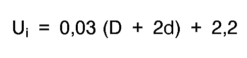
Ui est la tension d'arc minimale initiale, en kVcc, dudit produit final,
D est l'épaisseur effective, en micromètres, d'une couche (66) dudit matériau diélectrique placé entre lesdites première et deuxième électrodes et de ladite troisième électrode, et ,
d est l'épaisseur effective, en micromètres, de ladite couche de protection (68). - Procédé de fabrication d'un dispositif à décharge par effet corona selon la revendication 1, dans lequel lesdites première et deuxième électrodes (54 ; 56) sont coplanaires et dans lequel l'épaisseur effective d'une couche (66) dudit matériau diélectrique placé entre lesdites première et deuxième électrodes et ladite troisième électrode et l'épaisseur effective de ladite couche de protection (68) sont sélectionnées pour satisfaire à la relation:

Vo est la tension de fonctionnement normale, en kVcc, dudit dispositif à décharge par effet corona,
D est l'épaisseur effective, en micromètres, d'une couche (66) dudit matériau diélectrique placé entre lesdites première et deuxième électrodes et ladite troisième électrode, et ,
d est l'épaisseur effective, en micromètres, de ladite couche de protection - Procédé de fabrication d'un dispositif à décharge par effet corona selon la revendication 1, dans lequel l'épaisseur effective d'une couche (66) dudit matériau diélectrique placé entre lesdites première et deuxième électrodes et ladite troisième électrode est sélectionnée entre 25 et 70 micromètres environ et l'épaisseur effective de ladite couche de protection (68) est sélectionnée entre 7 et 20 micromètres environ pour que ledit produit final fonctionne à une tension de fonctionnement égale ou inférieure à environ 6 kVcc.
- Procédé de fabrication d'un dispositif à décharge par effet corona selon la revendication 1, dans lequel ladite troisième électrode (64) est configurée pour présenter des coins arrondis afin d'éviter la concentration d'effluve de décharge par effet corona.
- Procédé de fabrication d'un dispositif à décharge par effet corona selon la revendication 1, dans lequel ladite troisième électrode (64) a une longueur qui s'étend au-delà du contour d'au moins l'une desdites première et deuxième électrodes (54/56) pour que la décharge par effet corona soit générée entre l'une desdites électrodes et ladite troisième électrode uniquement le long de parties linéaires du contour de ladite troisième électrode.
- Procédé de fabrication d'un dispositif à décharge par effet corona selon la revendication 1, dans lequel ledit dispositif est conçu et construit de telle sorte que la capacité électrostatique établie entre lesdites première et troisième électrode (54 ; 64) est différente de celle établie entre lesdites deuxième et troisième électrodes (56 ; 64).
- Procédé de fabrication d'un dispositif à décharge par effet corona selon la revendication 10, dans lequel la zone (S1) dans laquelle ladite troisième électrode est superposée sur l'une desdites première et deuxième électrodes est plus grande que la zone (S2) dans laquelle ladite troisième électrode est superposée sur l'autre desdites première et deuxième électrodes.
- Procédé de fabrication d'un dispositif à décharge par effet corona selon la revendication 10, dans lequel la distance (D1) entre lesdites première et troisième électrodes est différente de la distance (D2) entre lesdites deuxième et troisième électrodes.
- Procédé de fabrication d'un dispositif à décharge par effet corona selon la revendication 10, dans lequel la constante diélectrique d'une couche dudit matériau diélectrique placé entre lesdites première et troisième électrodes est différente de celle d'une couche dudit matériau diélectrique placé entre lesdites deuxième et troisième électrodes.
- Procédé de fabrication d'un dispositif (50) à décharge par effet corona, comprenant les étapes suivantes :
préparation d'un produit préliminaire (96) de dispositif à décharge par effet corona ayant une première et une deuxième électrodes planar (54 ; 56) noyées dans un substrat (52) de matériau diélectrique dans une relation coplanaire espacée latéralement l'une de l'autre, des moyens de connexion (70/74 ; 72/76) reliés auxdites première et deuxième électrodes pour appliquer une tension alternative haute fréquence entre celles-ci, une troisième électrode flottante (64) disposée sur ledit substrat et couplée capacitivement, tout en restant espacée desdites première et deuxième électrodes, et une couche de protection (68) en matériau isolant électriquement et résistant chimiquement recouvrant ladite troisième électrode, ledit produit préliminaire (96) ayant originalement un niveau de tension d'arc minimale initiale auquel la décharge par effet corona serait générée presque instantanément dès l'application d'une tension alternative haute fréquence ; et,
application pendant un temps prédéterminé entre lesdites première et deuxième électrodes dudit produit préliminaire d'une tension alternative haute fréquence ayant un niveau de tension supérieur audit niveau de tension d'arc minimale initiale dudit produit préliminaire, provoquant, de ce fait, l'établissement d'une décharge par effet corona sur ladite couche de protection pour vieillir ladite couche de protection, grâce à quoi un produit final de dispositif à décharge par effet corona ayant un niveau de tension de fonctionnement efficace inférieur audit niveau de tension d'arc minimale initiale est obtenu. - Procédé de fabrication d'un dispositif (50) à décharge par effet corona, comprenant les étapes suivantes :
préparation d'une plaque verte de matériau diélectrique formant céramique ;
formation d'une paire de trous de passage espacés (84) dans l'épaisseur de ladite plaque verte :
remplissage desdits trous avec une pâte (86) contenant des particules métalliques pour former une paire de motifs de connexions électriques espacés ;
formation d'une paire de motifs d'électrodes espacés (88) de ladite pâte sur une surface de ladite plaque verte en contact, respectivement, avec lesdits motifs de connexions ;
formation d'une couche (66) de matériau diélectrique formant céramique sur lesdits motifs d'électrodes ;
formation d'un autre motif d'électrode (94) de ladite pâte sur ladite couche de matériau diélectrique formant céramique en relation de superposition au moins partielle par rapport auxdits motifs d'électrodes espacés ;
revêtement dudit autre motif d'électrode d'une couche de protection (68) de matériau isolant électriquement et résistant chimiquement ;
frittage du produit ainsi formé pour obtenir un produit préliminaire (96) du dispositif à décharge par effet corona ; et,
amorçage d'une décharge par effet corona par ledit produit préliminaire jusqu'au vieillissement de ladite couche de protection.
Applications Claiming Priority (4)
| Application Number | Priority Date | Filing Date | Title |
|---|---|---|---|
| JP1991091833U JP2526706Y2 (ja) | 1991-10-14 | 1991-10-14 | オゾナイザ |
| JP91833/91U | 1991-10-14 | ||
| JP78863/92 | 1992-02-28 | ||
| JP04078863A JP3117034B2 (ja) | 1992-02-28 | 1992-02-28 | コロナ放電器 |
Publications (2)
| Publication Number | Publication Date |
|---|---|
| EP0537613A1 EP0537613A1 (fr) | 1993-04-21 |
| EP0537613B1 true EP0537613B1 (fr) | 1995-08-09 |
Family
ID=26419927
Family Applications (1)
| Application Number | Title | Priority Date | Filing Date |
|---|---|---|---|
| EP92117128A Expired - Lifetime EP0537613B1 (fr) | 1991-10-14 | 1992-10-07 | Méthode de fabrication d'un appareil à décharge corona |
Country Status (6)
| Country | Link |
|---|---|
| US (1) | US5407639A (fr) |
| EP (1) | EP0537613B1 (fr) |
| AT (1) | ATE126177T1 (fr) |
| CA (1) | CA2079538C (fr) |
| DE (1) | DE69204008T2 (fr) |
| ES (1) | ES2076644T3 (fr) |
Families Citing this family (48)
| Publication number | Priority date | Publication date | Assignee | Title |
|---|---|---|---|---|
| ES2074029B1 (es) * | 1994-01-20 | 1996-03-16 | Serra Jaime Tona | Dispositivo para ozonizar peque¦as zonas o superficies con fines terapeuticos. |
| US5606723A (en) * | 1995-01-25 | 1997-02-25 | Zpm, Inc. | Apparatus for delivering electromagnetic energy into a solution |
| US6024930A (en) * | 1996-08-08 | 2000-02-15 | Quantum Electronics Corporation | Ozone generator plate |
| US5742051A (en) * | 1996-09-26 | 1998-04-21 | Xerox Corporation | Micro sized ion generating device |
| US5866082A (en) * | 1997-03-27 | 1999-02-02 | Omega 5 Technologies Inc. | Hand-held ozone-producing apparatus |
| DE19822841B4 (de) * | 1998-05-22 | 2006-01-12 | Schott Ag | Ozonisator und Verfahren zur Herstellung eines solchen |
| US6284205B1 (en) * | 1998-08-21 | 2001-09-04 | Kabushiki Kaisha Toshiba | Ozonizing unit ozone generator and ozone-processing system |
| US7695690B2 (en) | 1998-11-05 | 2010-04-13 | Tessera, Inc. | Air treatment apparatus having multiple downstream electrodes |
| US6544485B1 (en) | 2001-01-29 | 2003-04-08 | Sharper Image Corporation | Electro-kinetic device with enhanced anti-microorganism capability |
| US7318856B2 (en) | 1998-11-05 | 2008-01-15 | Sharper Image Corporation | Air treatment apparatus having an electrode extending along an axis which is substantially perpendicular to an air flow path |
| US6176977B1 (en) | 1998-11-05 | 2001-01-23 | Sharper Image Corporation | Electro-kinetic air transporter-conditioner |
| US20050210902A1 (en) | 2004-02-18 | 2005-09-29 | Sharper Image Corporation | Electro-kinetic air transporter and/or conditioner devices with features for cleaning emitter electrodes |
| US7220295B2 (en) | 2003-05-14 | 2007-05-22 | Sharper Image Corporation | Electrode self-cleaning mechanisms with anti-arc guard for electro-kinetic air transporter-conditioner devices |
| US6338827B1 (en) * | 1999-06-29 | 2002-01-15 | Delphi Technologies, Inc. | Stacked shape plasma reactor design for treating auto emissions |
| DE19931366A1 (de) * | 1999-07-07 | 2001-02-01 | T E M Gmbh | Flache Baugruppe zur elektrischen Erzeugung eines Plasmas in Luft |
| US6821493B2 (en) * | 2001-04-02 | 2004-11-23 | Delphi Technologies, Inc. | Non-thermal plasma reactor substrate design-E-shape with low loss electrode pattern |
| SK6292001A3 (en) * | 2001-05-04 | 2002-11-06 | Mirko Cernak | Method and device for the treatment of textile materials |
| DE10203543B4 (de) * | 2002-01-29 | 2008-04-30 | Je Plasmaconsult Gmbh | Vorrichtung zur Erzeugung eines APG-Plasmas |
| US7029637B2 (en) * | 2003-01-09 | 2006-04-18 | H203, Inc. | Apparatus for ozone production, employing line and grooved electrodes |
| US20040136885A1 (en) * | 2003-01-09 | 2004-07-15 | Hogarth Derek J. | Apparatus and method for generating ozone |
| US7727487B2 (en) * | 2003-02-12 | 2010-06-01 | Ngk Insulators, Ltd. | Plasma reaction vessel, and method of producing the same |
| US7405672B2 (en) | 2003-04-09 | 2008-07-29 | Sharper Image Corp. | Air treatment device having a sensor |
| US7906080B1 (en) | 2003-09-05 | 2011-03-15 | Sharper Image Acquisition Llc | Air treatment apparatus having a liquid holder and a bipolar ionization device |
| US7077890B2 (en) | 2003-09-05 | 2006-07-18 | Sharper Image Corporation | Electrostatic precipitators with insulated driver electrodes |
| US7724492B2 (en) | 2003-09-05 | 2010-05-25 | Tessera, Inc. | Emitter electrode having a strip shape |
| US7517503B2 (en) | 2004-03-02 | 2009-04-14 | Sharper Image Acquisition Llc | Electro-kinetic air transporter and conditioner devices including pin-ring electrode configurations with driver electrode |
| US20050051420A1 (en) | 2003-09-05 | 2005-03-10 | Sharper Image Corporation | Electro-kinetic air transporter and conditioner devices with insulated driver electrodes |
| US7282274B2 (en) * | 2003-11-07 | 2007-10-16 | General Electric Company | Integral composite structural material |
| US7767169B2 (en) | 2003-12-11 | 2010-08-03 | Sharper Image Acquisition Llc | Electro-kinetic air transporter-conditioner system and method to oxidize volatile organic compounds |
| US7638104B2 (en) | 2004-03-02 | 2009-12-29 | Sharper Image Acquisition Llc | Air conditioner device including pin-ring electrode configurations with driver electrode |
| JP4320637B2 (ja) * | 2004-04-08 | 2009-08-26 | 三菱電機株式会社 | オゾン発生装置およびオゾン発生方法 |
| US7285155B2 (en) | 2004-07-23 | 2007-10-23 | Taylor Charles E | Air conditioner device with enhanced ion output production features |
| US20060016333A1 (en) | 2004-07-23 | 2006-01-26 | Sharper Image Corporation | Air conditioner device with removable driver electrodes |
| US7311762B2 (en) | 2004-07-23 | 2007-12-25 | Sharper Image Corporation | Air conditioner device with a removable driver electrode |
| US7833322B2 (en) | 2006-02-28 | 2010-11-16 | Sharper Image Acquisition Llc | Air treatment apparatus having a voltage control device responsive to current sensing |
| DE102008006256B4 (de) * | 2008-01-25 | 2026-04-23 | Innovative Sensor Technology Ist Ag | Baugruppe zur Erzeugung von Ozon |
| DE102010011132A1 (de) * | 2010-03-11 | 2011-09-15 | Reinhausen Plasma Gmbh | Verfahren und Anordnung zur Plasmabehandlung eines Gasstroms |
| DE102010011131A1 (de) * | 2010-03-11 | 2011-09-15 | Reinhausen Plasma Gmbh | Plasmaerzeuger |
| JP2013166660A (ja) * | 2012-02-14 | 2013-08-29 | Murata Mfg Co Ltd | オゾン発生素子及びその製造方法 |
| US9308537B2 (en) | 2012-12-26 | 2016-04-12 | Igor Krichtafovitch | Electrostatic air conditioner |
| WO2014105217A1 (fr) * | 2012-12-26 | 2014-07-03 | Igor Krichtafovitch | Climatisation électrostatique |
| JP6547826B2 (ja) * | 2015-06-08 | 2019-07-24 | 株式会社村田製作所 | オゾン生成装置 |
| EP3118884A1 (fr) | 2015-07-15 | 2017-01-18 | Nederlandse Organisatie voor toegepast- natuurwetenschappelijk onderzoek TNO | Ensemble d'électrodes pour une source de plasma de décharge à barrière diélectrique et procédé de fabrication d'un tel ensemble d'électrode |
| DE102015213975A1 (de) * | 2015-07-23 | 2017-01-26 | Terraplasma Gmbh | Elektrodenanordnung und Plasmaquelle zur Erzeugung eines nicht-thermischen Plasmas sowie ein Verfahren zum Betreiben einer Plasmaquelle |
| US9913359B1 (en) | 2016-08-17 | 2018-03-06 | General Electric Company | Krypton-85-free spark gap with cantilevered component |
| CN108759654B (zh) * | 2018-06-27 | 2023-05-30 | 南京铁道职业技术学院 | 一种单探头受电弓碳滑板表面低凹缝隙测量用变换器 |
| CN114814499B (zh) * | 2022-05-17 | 2024-07-02 | 中国南方电网有限责任公司超高压输电公司检修试验中心 | 绝缘材料电晕老化试验装置及试验方法 |
| DE102023127759B3 (de) | 2023-10-11 | 2025-02-13 | Tdk Electronics Ag | Vorrichtung zur Erzeugung einer dielektrischen Barriereentladung und Verfahren zur Herstellung einer solchen Vorrichtung |
Family Cites Families (27)
| Publication number | Priority date | Publication date | Assignee | Title |
|---|---|---|---|---|
| JPS58108559A (ja) * | 1981-12-23 | 1983-06-28 | Fuji Xerox Co Ltd | 電子複写機等の帯電装置 |
| JPS5944797A (ja) * | 1982-09-07 | 1984-03-13 | 増田 閃一 | 物体の静電的処理装置 |
| US4545960A (en) * | 1983-03-04 | 1985-10-08 | Erz Gerhard J | Fluid treatment system and ozone generator therefor |
| US4626876A (en) * | 1984-01-25 | 1986-12-02 | Ricoh Company, Ltd. | Solid state corona discharger |
| JPS60157183A (ja) * | 1984-01-25 | 1985-08-17 | 株式会社リコー | 固体放電装置 |
| GB2156598B (en) * | 1984-03-26 | 1988-03-02 | Canon Kk | Device and method for charging or discharging |
| JPS60176443U (ja) * | 1984-04-28 | 1985-11-22 | 増田 閃一 | 電界装置 |
| US4666679A (en) * | 1984-07-18 | 1987-05-19 | Ngk Spark Plug Co., Ltd. | Ceramic ozonizer |
| JPS61231573A (ja) * | 1985-04-05 | 1986-10-15 | Senichi Masuda | コロナ放電器 |
| DE3521985A1 (de) * | 1985-05-21 | 1986-11-27 | BBC Aktiengesellschaft Brown, Boveri & Cie., Baden, Aargau | Ozonerzeuger |
| JPS6251463A (ja) * | 1985-08-30 | 1987-03-06 | Canon Inc | 放電装置 |
| JPS6263953A (ja) * | 1985-09-17 | 1987-03-20 | Ricoh Co Ltd | 固体放電装置 |
| US4783716A (en) * | 1986-01-30 | 1988-11-08 | Canon Kabushiki Kaisha | Charging or discharging device |
| US4794254A (en) * | 1987-05-28 | 1988-12-27 | Xerox Corporation | Distributed resistance corona charging device |
| JPS6433004A (en) * | 1987-07-24 | 1989-02-02 | Matsushita Refrigeration | Ozonizer |
| JPH01117240A (ja) * | 1987-10-30 | 1989-05-10 | Masao Iwanaga | 放電素子およびその応用装置 |
| JPH01128822A (ja) * | 1987-11-14 | 1989-05-22 | Koito Mfg Co Ltd | 車両用灯具ボディのブロー成形方法 |
| US4940894A (en) * | 1987-12-10 | 1990-07-10 | Enercon Industries Corporation | Electrode for a corona discharge apparatus |
| JPH0764523B2 (ja) * | 1988-03-25 | 1995-07-12 | 京セラ株式会社 | オゾン発生用放電体 |
| US4892713A (en) * | 1988-06-01 | 1990-01-09 | Newman James J | Ozone generator |
| JPH02130568A (ja) * | 1988-11-10 | 1990-05-18 | Toshiba Corp | イオン発生装置 |
| JP2907439B2 (ja) * | 1989-05-09 | 1999-06-21 | 松下電器産業株式会社 | ファインセラミック沿面放電体 |
| JPH03190077A (ja) * | 1989-12-19 | 1991-08-20 | Toto Ltd | コロナ放電器 |
| US5027136A (en) * | 1990-01-16 | 1991-06-25 | Dennison Manufacturing Company | Method and apparatus for charged particle generation |
| KR920003216B1 (en) * | 1990-03-03 | 1992-04-24 | Samsung Electronic | Apparatus for the production of ozone |
| US5272414A (en) * | 1990-05-08 | 1993-12-21 | I.T.M. Corporation | Discharge element, method of producing the same and apparatus comprising the same |
| US5043579A (en) * | 1990-06-27 | 1991-08-27 | Xerox Corporation | Uniform charging device |
-
1992
- 1992-09-30 CA CA002079538A patent/CA2079538C/fr not_active Expired - Fee Related
- 1992-09-30 US US07/953,356 patent/US5407639A/en not_active Expired - Fee Related
- 1992-10-07 DE DE69204008T patent/DE69204008T2/de not_active Expired - Fee Related
- 1992-10-07 EP EP92117128A patent/EP0537613B1/fr not_active Expired - Lifetime
- 1992-10-07 AT AT92117128T patent/ATE126177T1/de active
- 1992-10-07 ES ES92117128T patent/ES2076644T3/es not_active Expired - Lifetime
Non-Patent Citations (1)
| Title |
|---|
| CHEMICAL ABSTRACTS, vol. 113, no. 26, 24 December 1990, Columbus, Ohio, US; & abstract no. 234109w & JP-A-2 180 703, 13 July 1090 * |
Also Published As
| Publication number | Publication date |
|---|---|
| DE69204008T2 (de) | 1996-02-22 |
| DE69204008D1 (de) | 1995-09-14 |
| EP0537613A1 (fr) | 1993-04-21 |
| CA2079538A1 (fr) | 1993-04-15 |
| US5407639A (en) | 1995-04-18 |
| ES2076644T3 (es) | 1995-11-01 |
| ATE126177T1 (de) | 1995-08-15 |
| CA2079538C (fr) | 2000-11-21 |
Similar Documents
| Publication | Publication Date | Title |
|---|---|---|
| EP0537613B1 (fr) | Méthode de fabrication d'un appareil à décharge corona | |
| DE69016456T2 (de) | Elektrochemische zelle zur anreicherung von sauerstoff auf basis eines keramischen festelektrolyten. | |
| DE69030098T2 (de) | Gassensor mit festem Elektrolyt und Verfahren zum Messen der Konzentration des zu detektierenden Gases in einer Gasmischung | |
| US6270906B1 (en) | Monolithic ceramic electronic component | |
| EP2400605A1 (fr) | Élément absorbant une surintensité | |
| DE3907312A1 (de) | Keramische widerstandsheizeinrichtung mit untereinander verbundenen waermeentwickelnden leitern und eine derartige heizeinrichtung verwendendes elektrochemisches element oder analysiergeraet | |
| KR100464466B1 (ko) | 센서소자및그제조방법 | |
| CA2276351C (fr) | Detecteur de gaz halogene | |
| EP0512500B1 (fr) | Capteur d'oxygène et son procédé de fabrication | |
| DE68929412T2 (de) | Verfahren zur Bestimmung der Referenzstromstärke bei Nullfeuchtigheit für einen Feuchtigheitssensor unter Verwendung einer elektrochemischen Zelle | |
| US4947125A (en) | Method and device for determining oxygen in gases | |
| US5266079A (en) | Method for manufacturing a ceramic capacitor having varistor characteristics | |
| KR100239101B1 (ko) | 코로나 방전 장치 제조방법 | |
| JP2606785B2 (ja) | コロナ放電器の製造方法 | |
| US3998375A (en) | Bonding of metals to solid electrolytes | |
| WO1999029399A1 (fr) | Composition d'electrode et procede d'application pour des generateurs d'oxygene | |
| JPH1064703A (ja) | 積層チップ型電子部品 | |
| DE19912214A1 (de) | Hochspannungskeramikkondensator | |
| EP0732712A2 (fr) | Diélectrique pour condensateur et méthode de fabrication | |
| JPH0388702A (ja) | オゾン発生用放電体 | |
| JPS62278105A (ja) | オゾン発生器 | |
| EP0275364A1 (fr) | Pile à combustible à électrolyte solide et sa méthode de fabrication | |
| JP2993340B2 (ja) | ガスセンサ | |
| KR0159488B1 (ko) | 오존발생장치 | |
| JP3117034B2 (ja) | コロナ放電器 |
Legal Events
| Date | Code | Title | Description |
|---|---|---|---|
| PUAI | Public reference made under article 153(3) epc to a published international application that has entered the european phase |
Free format text: ORIGINAL CODE: 0009012 |
|
| AK | Designated contracting states |
Kind code of ref document: A1 Designated state(s): AT BE CH DE DK ES FR GB GR IE IT LI LU MC NL PT SE |
|
| 17P | Request for examination filed |
Effective date: 19930608 |
|
| 17Q | First examination report despatched |
Effective date: 19941216 |
|
| GRAA | (expected) grant |
Free format text: ORIGINAL CODE: 0009210 |
|
| AK | Designated contracting states |
Kind code of ref document: B1 Designated state(s): AT BE CH DE DK ES FR GB GR IE IT LI LU MC NL PT SE |
|
| PG25 | Lapsed in a contracting state [announced via postgrant information from national office to epo] |
Ref country code: NL Free format text: LAPSE BECAUSE OF FAILURE TO SUBMIT A TRANSLATION OF THE DESCRIPTION OR TO PAY THE FEE WITHIN THE PRESCRIBED TIME-LIMIT Effective date: 19950809 Ref country code: MC Free format text: LAPSE BECAUSE OF NON-PAYMENT OF DUE FEES Effective date: 19950809 Ref country code: GR Free format text: LAPSE BECAUSE OF FAILURE TO SUBMIT A TRANSLATION OF THE DESCRIPTION OR TO PAY THE FEE WITHIN THE PRESCRIBED TIME-LIMIT Effective date: 19950809 Ref country code: DK Effective date: 19950809 Ref country code: BE Effective date: 19950809 Ref country code: AT Effective date: 19950809 |
|
| REF | Corresponds to: |
Ref document number: 126177 Country of ref document: AT Date of ref document: 19950815 Kind code of ref document: T |
|
| REG | Reference to a national code |
Ref country code: IE Ref legal event code: FG4D Free format text: 64798 |
|
| REF | Corresponds to: |
Ref document number: 69204008 Country of ref document: DE Date of ref document: 19950914 |
|
| ITF | It: translation for a ep patent filed | ||
| PG25 | Lapsed in a contracting state [announced via postgrant information from national office to epo] |
Ref country code: LU Free format text: LAPSE BECAUSE OF NON-PAYMENT OF DUE FEES Effective date: 19951031 Ref country code: IE Free format text: LAPSE BECAUSE OF NON-PAYMENT OF DUE FEES Effective date: 19951031 |
|
| REG | Reference to a national code |
Ref country code: ES Ref legal event code: FG2A Ref document number: 2076644 Country of ref document: ES Kind code of ref document: T3 |
|
| PG25 | Lapsed in a contracting state [announced via postgrant information from national office to epo] |
Ref country code: SE Effective date: 19951109 Ref country code: PT Effective date: 19951109 |
|
| ET | Fr: translation filed | ||
| NLV1 | Nl: lapsed or annulled due to failure to fulfill the requirements of art. 29p and 29m of the patents act | ||
| PLBE | No opposition filed within time limit |
Free format text: ORIGINAL CODE: 0009261 |
|
| 26N | No opposition filed | ||
| PGFP | Annual fee paid to national office [announced via postgrant information from national office to epo] |
Ref country code: GB Payment date: 20011010 Year of fee payment: 10 Ref country code: FR Payment date: 20011010 Year of fee payment: 10 |
|
| PGFP | Annual fee paid to national office [announced via postgrant information from national office to epo] |
Ref country code: DE Payment date: 20011022 Year of fee payment: 10 |
|
| PGFP | Annual fee paid to national office [announced via postgrant information from national office to epo] |
Ref country code: ES Payment date: 20011025 Year of fee payment: 10 |
|
| PGFP | Annual fee paid to national office [announced via postgrant information from national office to epo] |
Ref country code: CH Payment date: 20011029 Year of fee payment: 10 |
|
| REG | Reference to a national code |
Ref country code: GB Ref legal event code: IF02 |
|
| PG25 | Lapsed in a contracting state [announced via postgrant information from national office to epo] |
Ref country code: GB Free format text: LAPSE BECAUSE OF NON-PAYMENT OF DUE FEES Effective date: 20021007 |
|
| PG25 | Lapsed in a contracting state [announced via postgrant information from national office to epo] |
Ref country code: ES Free format text: LAPSE BECAUSE OF NON-PAYMENT OF DUE FEES Effective date: 20021008 |
|
| PG25 | Lapsed in a contracting state [announced via postgrant information from national office to epo] |
Ref country code: LI Free format text: LAPSE BECAUSE OF NON-PAYMENT OF DUE FEES Effective date: 20021031 Ref country code: CH Free format text: LAPSE BECAUSE OF NON-PAYMENT OF DUE FEES Effective date: 20021031 |
|
| PG25 | Lapsed in a contracting state [announced via postgrant information from national office to epo] |
Ref country code: DE Free format text: LAPSE BECAUSE OF NON-PAYMENT OF DUE FEES Effective date: 20030501 |
|
| GBPC | Gb: european patent ceased through non-payment of renewal fee |
Effective date: 20021007 |
|
| REG | Reference to a national code |
Ref country code: CH Ref legal event code: PL |
|
| PG25 | Lapsed in a contracting state [announced via postgrant information from national office to epo] |
Ref country code: FR Free format text: LAPSE BECAUSE OF NON-PAYMENT OF DUE FEES Effective date: 20030630 |
|
| REG | Reference to a national code |
Ref country code: FR Ref legal event code: ST |
|
| REG | Reference to a national code |
Ref country code: ES Ref legal event code: FD2A Effective date: 20031112 |
|
| PG25 | Lapsed in a contracting state [announced via postgrant information from national office to epo] |
Ref country code: IT Free format text: LAPSE BECAUSE OF NON-PAYMENT OF DUE FEES Effective date: 20051007 |