EP0538487A1 - Umwerfer für ein fahrrad - Google Patents
Umwerfer für ein fahrrad Download PDFInfo
- Publication number
- EP0538487A1 EP0538487A1 EP92909785A EP92909785A EP0538487A1 EP 0538487 A1 EP0538487 A1 EP 0538487A1 EP 92909785 A EP92909785 A EP 92909785A EP 92909785 A EP92909785 A EP 92909785A EP 0538487 A1 EP0538487 A1 EP 0538487A1
- Authority
- EP
- European Patent Office
- Prior art keywords
- link mechanism
- members
- pivotal
- bicycle
- pantograph link
- Prior art date
- Legal status (The legal status is an assumption and is not a legal conclusion. Google has not performed a legal analysis and makes no representation as to the accuracy of the status listed.)
- Withdrawn
Links
Images


Classifications
-
- B—PERFORMING OPERATIONS; TRANSPORTING
- B62—LAND VEHICLES FOR TRAVELLING OTHERWISE THAN ON RAILS
- B62M—RIDER PROPULSION OF WHEELED VEHICLES OR SLEDGES; POWERED PROPULSION OF SLEDGES OR SINGLE-TRACK CYCLES; TRANSMISSIONS SPECIALLY ADAPTED FOR SUCH VEHICLES
- B62M9/00—Transmissions characterised by use of an endless chain, belt, or the like
- B62M9/04—Transmissions characterised by use of an endless chain, belt, or the like of changeable ratio
- B62M9/06—Transmissions characterised by use of an endless chain, belt, or the like of changeable ratio using a single chain, belt, or the like
- B62M9/10—Transmissions characterised by use of an endless chain, belt, or the like of changeable ratio using a single chain, belt, or the like involving different-sized wheels, e.g. rear sprocket chain wheels selectively engaged by the chain, belt, or the like
- B62M9/12—Transmissions characterised by use of an endless chain, belt, or the like of changeable ratio using a single chain, belt, or the like involving different-sized wheels, e.g. rear sprocket chain wheels selectively engaged by the chain, belt, or the like the chain, belt, or the like being laterally shiftable, e.g. using a rear derailleur
- B62M9/121—Rear derailleurs
- B62M9/124—Mechanisms for shifting laterally
- B62M9/1248—Mechanisms for shifting laterally characterised by the use of biasing means, e.g. springs; Arrangements thereof
-
- B—PERFORMING OPERATIONS; TRANSPORTING
- B62—LAND VEHICLES FOR TRAVELLING OTHERWISE THAN ON RAILS
- B62M—RIDER PROPULSION OF WHEELED VEHICLES OR SLEDGES; POWERED PROPULSION OF SLEDGES OR SINGLE-TRACK CYCLES; TRANSMISSIONS SPECIALLY ADAPTED FOR SUCH VEHICLES
- B62M9/00—Transmissions characterised by use of an endless chain, belt, or the like
- B62M9/04—Transmissions characterised by use of an endless chain, belt, or the like of changeable ratio
- B62M9/06—Transmissions characterised by use of an endless chain, belt, or the like of changeable ratio using a single chain, belt, or the like
- B62M9/10—Transmissions characterised by use of an endless chain, belt, or the like of changeable ratio using a single chain, belt, or the like involving different-sized wheels, e.g. rear sprocket chain wheels selectively engaged by the chain, belt, or the like
- B62M9/12—Transmissions characterised by use of an endless chain, belt, or the like of changeable ratio using a single chain, belt, or the like involving different-sized wheels, e.g. rear sprocket chain wheels selectively engaged by the chain, belt, or the like the chain, belt, or the like being laterally shiftable, e.g. using a rear derailleur
- B62M9/121—Rear derailleurs
- B62M9/124—Mechanisms for shifting laterally
- B62M9/1242—Mechanisms for shifting laterally characterised by the linkage mechanisms
Definitions
- the present invention relates to a bicycle derailleur. More specifically the present invention relates to a bicycle derailleur wherein pulling force of a control cable is transmitted efficiently for improved speed shift operatability.
- a bicycle derailleur a rear derailleur for instance, has a chain guide which rotatably supports a guide pulley and a tension pulley.
- This chain guide is pivotally supported via a shift link mechanism such as a parallelogram pantograph link mechanism while being elastically urged in a direction to tension a chain.
- a control lever which is connected by a control cable to the shift link mechanism, is operated, the shift link mechanism is deformed to cause the chain guide, which is supported by a movable member of the shift link mechanism, to move axially of a hub shaft, forcing the chain to move to a selected sprocket of a multiple free wheel.
- the derailleur is provided with a return spring which elastically urges the shift link mechanism constantly toward the returning direction.
- the shift link mechanism is forced to deform in a direction where the elastic force of the return spring is accumulated.
- the control lever is turned otherwise to release the control cable, the accumulated force of the return spring causes the shift link mechanism to return to the original position.
- This movement of the shift link mechanism causes the movable member which supports the chain guide to perform a reciprocal movement corresponding to the reciprocal turning movement of the control lever.
- the return spring is mounted conventionally around a pin which pivotally connects two adjacent members of the shift link mechanism. This return spring is mounted in such a way that ends of the spring elastically contact the respective constituent members of the shift link mechanism.
- the return spring will be contracted by an amount corresponding to a relative pivotal movement of the two members between which the ends of the return spring are placed: For instance, when these two members make a relative pivotal movement of 45° , the spring is also contracted by about 45 ° .
- the return spring's elastic force is proportional to its torsional deformation. This means that if the return spring receives a great amount of contraction such as described hereinabove within the shift link's deformation range, the difference in the spring's elastic force between beginning and ending phases of the shift link's deformation will also be great, posing a problem of deteriorated speed shift operatability.
- the control lever in order for the speed shift control lever to be retained at a selected rotational position, the control lever must be given a predetermined amount of friction resistance (or click resistance.)
- the amount of this resistance must be determined according to a maximum elastic force of the return spring. This means that as the elastic force of the return spring increases, a greater friction resistance must be provided, which results in a greater rotational resistance of the control lever with deteriorated operatability thereof. In addition, it calls for an increase in the size of a friction generating mechanism and the entire control lever assembly.
- the difference in elastic force caused by the difference of the return spring's contraction may be made smaller by increasing the number of windings of the coil spring, or in other words, by increasing an overall length of the spring wire.
- This solution will result in a very large coil spring to be used, with a decreased productivity in assembly process and an increased size and weight of the derailleur mounted with this coil spring.
- Another object of the present invention is to provide a bicycle derailleur wherein the derailleur and the control lever can be decreased in their size and weight.
- the present invention provides a bicycle derailleur comprising: a parallelogram pantograph link mechanism including a base member mounted to a bicycle frame, a parallel pair of link members each having a base end pivoted by a connecting pin to the base member, and a movable member pivoted by connecting pins to respective free ends of the link members; and a chain guide rotatably supporting a guide pulley and a tension pulley, the chain guide being moved laterally of the bicycle by the parallelogram pantograph link mechanism for speed change operation; characterized in that: the parallelogram pantograph link mechanism is provided with a first and second pivotal members each having a predetermined length and pivoted to a predetermined position of a different constituent member of the parallelogram pantograph link mechanism, respective free ends of the first and second pivotal members being mutually connected by a pin for causing the first and second pivotal members to pivot relative to the member to which they are pivoted when the parallelogram pantograph link mechanism is deformed; and a return spring is provided between the first or second pivotal member
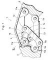
- Fig. 1 is a cross-sectional view showing an embodiment of a link mechanism according to the present invention.
- Fig. 2 is a cross-sectional view showing a deformed state of the link mechanism of Fig. 1.
- Fig. 3 is a cross-sectional view taken on the line III -III of Fig. 1.
- Fig. 4 is a schematic drawing to show a state of change in the link mechanism as depicted in Figs. 1 and 2.
- Fig. 5 is a schematic drawing to show a second embodiment of the present invention.
- Fig. 6 is a side view showing an entire configuration of a derailleur according to the present invention.
- the present embodiment is an application of the present invention to a rear derailleur 1 of a bicycle wherein a chain is shifted to a selected one of sprocket wheels on a multiple free wheel.
- a rear derailleur 1 has a parallelogram pantograph link mechanism 7 which comprises: a base member 3 which is mounted to a bicycle frame 2; a parallel pair of a first and second link members 4 and 5, each having a base end portion pivoted by respective connecting pins 11a, 11b to the base member 3; and a movable member 11 pivotally connected by connecting pins 11e, 11f to each free end portion of the first and second link members 4, 5.
- a chain guide 10 which rotatably supports a guide pulley 8 and a tension pulley 9, is rotatably supported. The speed shift operation is performed by causing the parallelogram pantograph link mechanism 7 to move the chain guide 10 laterally of the bicycle.
- the parallelogram pantograph link mechanism 7 is provided with: a first pivotal member 12, which is pivoted at its one end to the connecting pin 11a which connects the base member 3 and the first link member 4, being oriented inwardly of the parallelogram pantograph link mechanism; and a second pivotal member 13, which is pivoted at its one end to the connecting pin 11b which is provided at a predetermined position of an intermediate portion of the second link member 5. Another end portion of each of the first and second pivotal members 12, 13 is mutually connected by a connecting pin 11c.
- first and second pivotal members 12, 13, the base member 3, and a portion 5a of the second link member 5 between the connecting pins 11b and 11d forms an irregular quadrilateral (trapeziform) link mechanism 14 which is an additional link mechanism being a different link mechanism from the parallelogram pantograph link mechanism 7.
- a return spring 15 As shown in Figs. 1 and 3, with its end portions respectively contacting the base member 3 and the first pivotal member 12 thereby elastically urging the first pivotal member 12 in a clockwise direction as in Fig. 1.
- Fig. 4 shows a schematic diagram of the link mechanism according to Fig. 1.
- the rear derailleur has the parallelogram pantograph link mechanism 7 formed by the base member 3, the first and second link members 4, 5, and the movable member 6, and in addition to this, there is formed a trapeziform link mechanism 14 comprising the base member 3, the first and second pivotal members 12, 13, and the portion 5a between the connecting pin 11b of the second link member 13 and the connecting pin 11d.
- This trapeziform link mechanism 14 deforms correspondingly as the parallelogram pantograph link mechanism 7 deforms, and at the same time, the built-in return spring 15 provides the parallelogram pantograph link mechanism 7 with elastic returning force.
- the first pivotal member has a greater length than the portion 5a which is a portion between the connecting pins 11b and 11d of the second link member 5.
- a pivotal angle ⁇ which is an angle made by the relative pivotal movement of the first pivotal member 12 against the base member 3
- a pivotal angle ⁇ which is an angle made by the pivotal movement of the first link member 4 or the second link member 5 against the base member 3.
- the amount of contraction ⁇ of the return spring 15 is substantially smaller than in the conventional arrangement where the return spring is placed between the base member 3 and the first link member 4.
- the spring force from the return spring 15, in this embodiment is transmitted by the trapeziform link mechanism 14 to the parallelogram pantograph link mechanism 7, and the parallelogram pantograph link mechanism 7 is deformed against this particular spring force. Accordingly, with the momentum transmission efficiency from the trapeziform link mechanism 14 to the pantograph link mechanism 7 being equal, it is possible, by using the decrease in contraction of the return spring 15, to reduce the difference in the elastic returning force before and after the deformation of the parallelogram pantograph link mechanism 7.
- control lever assembly a smaller amount of friction resistance to hold the control cable W against the elastic pulling force by the return spring 15.
- rotational resistance of the control lever may be reduced for improved speed shift operatability and decreased size and weight in the derailleur and the control lever assembly.
- Fig. 5 shows a second embodiment of a derailleur according to the present invention.
- the first pivotal member 12 is pivoted, in the same way as in the first embodiment, to the connecting pin 11a which connects the first link member 4 and the base member 3, and the return spring 15 is placed between this first pivotal member 12 and the base member.
- an end of the second pivotal member 13 is pivoted to the connecting pin 11b which is provided at a free-end side of an intermediate portion of the second link member 5 whereas respective ends of the first and second pivotal members 12, 13 are connected by the pin 11c.
- the length and the connecting position of the first and second pivotal members 12, 13 are set so that an angle ⁇ formed by the second link member 5 and the second pivotal member 13 before the link mechanism's deformation has a relatively great value whereas an angle ⁇ ' formed by the second link member 5 and the second pivotal member 13 after the link mechanism's deformation is smaller.
- a link mechanism in general, can only trasmit force in a longitudinal direction. Therefore, when the angle ⁇ ' formed by the second link member 5 and the second pivotal member 13 becomes smaller as described above, most of the force transmitted by the second pivotal member 13 is shifted in a longitudinal direction of the second link member 5.
- the amount of contraction ⁇ of the return spring 15 is smaller than the pivotal movement angle ⁇ of the first link member 4, and furthermore it is possible to reduce the momentum transmission efficiency of the elastic force from the return spring 15 to the parallelogram pantograph link mechanism. Accordingly, it is possible to average the elastic returning force before and after deformation of the parallelogram pantograph link mechanism 7. This means that it is now possible to average the necessary force to pull the control cable W over the entire deformation range of the parallelogram pantograph link mechanism 7.
- the amount of force necessary to operate the control lever is also averaged, enabling increased speed shift operatability and decreased size and weight of both derailleur and the control lever assembly as has been mentioned in the first embodiment.
- each of the two pivotal members may be selected so that the first or second pivotal member has a smaller pivotal movement relative to the deformation of the parallelogram pantograph link mechanism, or so that these pivotal members form varied angles with their respective members to which they are connected.
- the first pivotal member 12 is pivoted to the connecting pin 11a which connects the base member 3 to the first link member 4, and the second pivotal member 13 is pivoted at a predetermined position of an intermediate portion of the second link member 5; however, the first and the second pivotal member 12, 13 may be pivoted to other members.
- the length of the first and second pivotal members 12, 13 may not be limited to those selected in the embodiments, and may be varied according to the elastic returning force, for example, of the parallelogram pantograph link mechanism.
- the arrangement used in the embodiments where the amount of contraction of the return spring 15 becomes smaller than in the conventional case may even be altered so as to increase the contraction of the return spring 15; even in that type of arrangement, it is possible to achieve the same functions by relying only on the decreased transmission efficiency of the momentum from the additional link mechanism 14 including the first and the second pivotal members 12, 13 to the parallelogram pantograph link mechanism 7.
- Another variation may include an application of the present invention to a front derailleur instead of a rear derailleur as applied in the embodiments.
- the return spring 15, which is placed between the base member 3 and the first pivotal member 12, may be placed elsewhere, for instance, between the first and second pivotal members 12 and 13.
Landscapes
- Engineering & Computer Science (AREA)
- Chemical & Material Sciences (AREA)
- Combustion & Propulsion (AREA)
- Transportation (AREA)
- Mechanical Engineering (AREA)
- Transmission Devices (AREA)
- Gear-Shifting Mechanisms (AREA)
Applications Claiming Priority (2)
| Application Number | Priority Date | Filing Date | Title |
|---|---|---|---|
| JP142430/91 | 1991-05-17 | ||
| JP3142430A JPH04342684A (ja) | 1991-05-17 | 1991-05-17 | 自転車用ディレーラ |
Publications (2)
| Publication Number | Publication Date |
|---|---|
| EP0538487A1 true EP0538487A1 (de) | 1993-04-28 |
| EP0538487A4 EP0538487A4 (en) | 1993-10-20 |
Family
ID=15315139
Family Applications (1)
| Application Number | Title | Priority Date | Filing Date |
|---|---|---|---|
| EP19920909785 Withdrawn EP0538487A4 (en) | 1991-05-17 | 1992-05-11 | Derailleur for bicycle |
Country Status (4)
| Country | Link |
|---|---|
| US (1) | US5302155A (de) |
| EP (1) | EP0538487A4 (de) |
| JP (1) | JPH04342684A (de) |
| WO (1) | WO1992020567A1 (de) |
Cited By (1)
| Publication number | Priority date | Publication date | Assignee | Title |
|---|---|---|---|---|
| US6923740B2 (en) * | 2001-11-26 | 2005-08-02 | Shimano Inc. | Front derailleur for a bicycle |
Families Citing this family (10)
| Publication number | Priority date | Publication date | Assignee | Title |
|---|---|---|---|---|
| JP3372616B2 (ja) * | 1993-11-30 | 2003-02-04 | 株式会社シマノ | 自転車用ディレーラ |
| US5695421A (en) * | 1996-02-21 | 1997-12-09 | Shimano Inc. | Elastomer coated coil spring and chain derailleur employing same |
| US5860880A (en) * | 1996-11-21 | 1999-01-19 | Shimano, Inc. | Low normal bicycle derailleur which allows lateral movement of the chain guide toward the rear wheel in response to a force directed laterally towards the rear wheel |
| US6638190B2 (en) * | 1997-12-24 | 2003-10-28 | Richard A. Patterson | Compact hydraulically-operated derailleur shifting system for bicycles |
| US6315688B1 (en) * | 1998-09-10 | 2001-11-13 | Sram Corporation | Derailleur link |
| US7527571B2 (en) * | 2004-12-20 | 2009-05-05 | Shimano Inc. | Rear derailleur for bicycle |
| US8057332B2 (en) * | 2009-01-22 | 2011-11-15 | Shimano Inc. | Bicycle derailleur |
| US9327792B2 (en) | 2011-01-28 | 2016-05-03 | Paha Designs, Llc | Gear transmission and derailleur system |
| US10207772B2 (en) | 2011-01-28 | 2019-02-19 | Paha Designs, Llc | Gear transmission and derailleur system |
| US9033833B2 (en) | 2011-01-28 | 2015-05-19 | Paha Designs, Llc | Gear transmission and derailleur system |
Family Cites Families (11)
| Publication number | Priority date | Publication date | Assignee | Title |
|---|---|---|---|---|
| JPS5247238A (en) * | 1975-10-13 | 1977-04-14 | Shimano Industrial Co | External transmission |
| JPS5391240A (en) * | 1977-01-21 | 1978-08-10 | Akihiro Yamamuro | Changeespeed gear of bicycle provided in the form of outer unit |
| US4626229A (en) * | 1983-05-09 | 1986-12-02 | Shimano Industrial Company Limited | Derailleur for a bicycle |
| JPS6112486A (ja) * | 1984-06-28 | 1986-01-20 | 株式会社シマノ | 自転車用デイレ−ラ− |
| FR2575434B1 (fr) * | 1984-12-28 | 1989-05-19 | Huret & Fils | Dispositif de commande, notamment pour derailleur de cycle |
| JPH065935B2 (ja) * | 1986-07-14 | 1994-01-19 | コニカ株式会社 | スチルビデオカメラ |
| JPS63199896U (de) * | 1987-06-12 | 1988-12-22 | ||
| US4789379A (en) * | 1987-10-06 | 1988-12-06 | Maeda Industries, Ltd. | Bicycle deraileur |
| JPH0352297U (de) * | 1989-09-28 | 1991-05-21 | ||
| US5134897A (en) * | 1989-10-20 | 1992-08-04 | Campagnolo S.R.L. | Twist-grip device for operating the gears of a bicycle |
| JPH04260889A (ja) * | 1991-02-13 | 1992-09-16 | Maeda Kogyo Kk | 自転車用変速操作装置 |
-
1991
- 1991-05-17 JP JP3142430A patent/JPH04342684A/ja active Pending
-
1992
- 1992-05-11 US US07/949,828 patent/US5302155A/en not_active Expired - Fee Related
- 1992-05-11 WO PCT/JP1992/000603 patent/WO1992020567A1/ja not_active Ceased
- 1992-05-11 EP EP19920909785 patent/EP0538487A4/en not_active Withdrawn
Non-Patent Citations (1)
| Title |
|---|
| See references of WO9220567A1 * |
Cited By (2)
| Publication number | Priority date | Publication date | Assignee | Title |
|---|---|---|---|---|
| US6923740B2 (en) * | 2001-11-26 | 2005-08-02 | Shimano Inc. | Front derailleur for a bicycle |
| US6962544B2 (en) | 2001-11-26 | 2005-11-08 | Shimano, Inc. | Front derailleur for a bicycle |
Also Published As
| Publication number | Publication date |
|---|---|
| US5302155A (en) | 1994-04-12 |
| JPH04342684A (ja) | 1992-11-30 |
| EP0538487A4 (en) | 1993-10-20 |
| WO1992020567A1 (fr) | 1992-11-26 |
Similar Documents
| Publication | Publication Date | Title |
|---|---|---|
| US4619633A (en) | Derailleur for a bicycle | |
| EP0655386B1 (de) | Schaltwerk für ein Fahrrad | |
| US5302155A (en) | Bicycle derailleur | |
| US4693700A (en) | Derailleur shifter | |
| EP0718184B1 (de) | Frontgangschaltung mit unabhängiger, bewegbarer Kettenführung | |
| EP0006021B1 (de) | Kettenrad-Gangschaltung | |
| US5037355A (en) | Bicycle front derailleur | |
| US3979962A (en) | Bicycle gear shift derailleur | |
| US5380253A (en) | Bicycle rear derailleur | |
| EP0013136A1 (de) | Gangwechselvorrichtung für Fahrrad | |
| EP0133057B1 (de) | Hinterradkettenschaltung | |
| US4194409A (en) | Front derailleur for a bicycle provided with a swingingly movable chain guide | |
| CN100513250C (zh) | 用于在自行车传动装置中变速的辅助装置 | |
| US4604078A (en) | Three-stage speed change front derailleur | |
| US20210155318A1 (en) | Derailleur for human-powered vehicle | |
| CN100422040C (zh) | 可调式自行车拨链器 | |
| US5524734A (en) | Brake apparatus for a bicycle which corrects braking force in a region of strong braking force | |
| US6093122A (en) | Hybrid spring for bicycle derailleurs | |
| US5038907A (en) | Operating device for a motor vehicle clutch | |
| US4778436A (en) | Front derailleur for a bicycle | |
| US4955849A (en) | Front derailleur for use in bicycle | |
| JPH03292280A (ja) | 自転車用制動操作装置 | |
| US4343613A (en) | Derailler system | |
| EP1106498A2 (de) | Motorische Antriebseinheit für ein Fahrrad | |
| US5775173A (en) | Actuating device for a cable line |
Legal Events
| Date | Code | Title | Description |
|---|---|---|---|
| PUAI | Public reference made under article 153(3) epc to a published international application that has entered the european phase |
Free format text: ORIGINAL CODE: 0009012 |
|
| 17P | Request for examination filed |
Effective date: 19930210 |
|
| AK | Designated contracting states |
Kind code of ref document: A1 Designated state(s): DE FR IT |
|
| A4 | Supplementary search report drawn up and despatched |
Effective date: 19930831 |
|
| AK | Designated contracting states |
Kind code of ref document: A4 Designated state(s): DE FR IT |
|
| 17Q | First examination report despatched |
Effective date: 19941024 |
|
| 18D | Application deemed to be withdrawn |
Effective date: 19941201 |