EP0538545B1 - Dispositif de bobinage d'une bobine de transformateur pour l'énroulement de fil sur un corps de bobine, permettant de compter correctement le nombre de spires et de bobiner à grande vitesse - Google Patents
Dispositif de bobinage d'une bobine de transformateur pour l'énroulement de fil sur un corps de bobine, permettant de compter correctement le nombre de spires et de bobiner à grande vitesse Download PDFInfo
- Publication number
- EP0538545B1 EP0538545B1 EP92105475A EP92105475A EP0538545B1 EP 0538545 B1 EP0538545 B1 EP 0538545B1 EP 92105475 A EP92105475 A EP 92105475A EP 92105475 A EP92105475 A EP 92105475A EP 0538545 B1 EP0538545 B1 EP 0538545B1
- Authority
- EP
- European Patent Office
- Prior art keywords
- winding
- bobbin
- coil
- coil bobbin
- transformer coil
- Prior art date
- Legal status (The legal status is an assumption and is not a legal conclusion. Google has not performed a legal analysis and makes no representation as to the accuracy of the status listed.)
- Expired - Lifetime
Links
- 238000004804 winding Methods 0.000 title claims description 228
- 230000003287 optical effect Effects 0.000 claims description 34
- 239000002184 metal Substances 0.000 claims description 20
- 229910052751 metal Inorganic materials 0.000 claims description 20
- 238000001514 detection method Methods 0.000 claims description 15
- 230000004044 response Effects 0.000 claims description 9
- 239000003989 dielectric material Substances 0.000 claims description 2
- 230000002401 inhibitory effect Effects 0.000 claims 2
- 238000000034 method Methods 0.000 description 15
- 238000004519 manufacturing process Methods 0.000 description 14
- 230000000994 depressogenic effect Effects 0.000 description 5
- 241000562569 Riodinidae Species 0.000 description 3
- XEEYBQQBJWHFJM-UHFFFAOYSA-N Iron Chemical group [Fe] XEEYBQQBJWHFJM-UHFFFAOYSA-N 0.000 description 2
- 244000145845 chattering Species 0.000 description 2
- 239000003086 colorant Substances 0.000 description 2
- 238000010276 construction Methods 0.000 description 2
- 238000010586 diagram Methods 0.000 description 2
- VIKNJXKGJWUCNN-XGXHKTLJSA-N norethisterone Chemical compound O=C1CC[C@@H]2[C@H]3CC[C@](C)([C@](CC4)(O)C#C)[C@@H]4[C@@H]3CCC2=C1 VIKNJXKGJWUCNN-XGXHKTLJSA-N 0.000 description 2
- 238000006243 chemical reaction Methods 0.000 description 1
- 230000000977 initiatory effect Effects 0.000 description 1
- 239000004033 plastic Substances 0.000 description 1
Images





Classifications
-
- H—ELECTRICITY
- H01—ELECTRIC ELEMENTS
- H01F—MAGNETS; INDUCTANCES; TRANSFORMERS; SELECTION OF MATERIALS FOR THEIR MAGNETIC PROPERTIES
- H01F41/00—Apparatus or processes specially adapted for manufacturing or assembling magnets, inductances or transformers; Apparatus or processes specially adapted for manufacturing materials characterised by their magnetic properties
-
- H—ELECTRICITY
- H01—ELECTRIC ELEMENTS
- H01F—MAGNETS; INDUCTANCES; TRANSFORMERS; SELECTION OF MATERIALS FOR THEIR MAGNETIC PROPERTIES
- H01F41/00—Apparatus or processes specially adapted for manufacturing or assembling magnets, inductances or transformers; Apparatus or processes specially adapted for manufacturing materials characterised by their magnetic properties
- H01F41/02—Apparatus or processes specially adapted for manufacturing or assembling magnets, inductances or transformers; Apparatus or processes specially adapted for manufacturing materials characterised by their magnetic properties for manufacturing cores, coils, or magnets
- H01F41/04—Apparatus or processes specially adapted for manufacturing or assembling magnets, inductances or transformers; Apparatus or processes specially adapted for manufacturing materials characterised by their magnetic properties for manufacturing cores, coils, or magnets for manufacturing coils
- H01F41/06—Coil winding
- H01F41/098—Mandrels; Formers
-
- H—ELECTRICITY
- H01—ELECTRIC ELEMENTS
- H01F—MAGNETS; INDUCTANCES; TRANSFORMERS; SELECTION OF MATERIALS FOR THEIR MAGNETIC PROPERTIES
- H01F41/00—Apparatus or processes specially adapted for manufacturing or assembling magnets, inductances or transformers; Apparatus or processes specially adapted for manufacturing materials characterised by their magnetic properties
- H01F41/02—Apparatus or processes specially adapted for manufacturing or assembling magnets, inductances or transformers; Apparatus or processes specially adapted for manufacturing materials characterised by their magnetic properties for manufacturing cores, coils, or magnets
- H01F41/04—Apparatus or processes specially adapted for manufacturing or assembling magnets, inductances or transformers; Apparatus or processes specially adapted for manufacturing materials characterised by their magnetic properties for manufacturing cores, coils, or magnets for manufacturing coils
- H01F41/06—Coil winding
- H01F41/064—Winding non-flat conductive wires, e.g. rods, cables or cords
-
- H—ELECTRICITY
- H01—ELECTRIC ELEMENTS
- H01F—MAGNETS; INDUCTANCES; TRANSFORMERS; SELECTION OF MATERIALS FOR THEIR MAGNETIC PROPERTIES
- H01F41/00—Apparatus or processes specially adapted for manufacturing or assembling magnets, inductances or transformers; Apparatus or processes specially adapted for manufacturing materials characterised by their magnetic properties
- H01F41/02—Apparatus or processes specially adapted for manufacturing or assembling magnets, inductances or transformers; Apparatus or processes specially adapted for manufacturing materials characterised by their magnetic properties for manufacturing cores, coils, or magnets
- H01F41/04—Apparatus or processes specially adapted for manufacturing or assembling magnets, inductances or transformers; Apparatus or processes specially adapted for manufacturing materials characterised by their magnetic properties for manufacturing cores, coils, or magnets for manufacturing coils
- H01F41/06—Coil winding
- H01F41/082—Devices for guiding or positioning the winding material on the former
Definitions
- the present invention relates to a transformer coil winding apparatus, more particularly, to a transformer coil winding apparatus for winding a winding wire on a coil bobbin to constitute a transformer.
- a transformer is for example, constituted by the way that a cylindrical coil bobbin is mounted to a non-cut iron core of essentially circular cross section, and the winding wire (coil) is wound by rotation of the coil bobbin.
- gear teeth are formed on the outer periphery of the coil bobbin to mesh with a gear of a drive shaft, whereby synchronization of a drive motor and the coil bobbin is established for accurately obtaining the number of turns of the winding wire unto the fraction.
- the shifting magnitude is determined depending upon the diameter of the winding wire. Further, the diameter of the winding wire may fluctuate, and thus fine adjustment of a traverse operation cannot be obtained. Further, in the transformer coil winding apparatus of the related art, a reversal operation of the traverse shift is carried out by actuating the limit switch with the traverse unit when the winding wire (coil) abuts the flange at either side end of the coil bobbin.
- the gear teeth are formed on the outer periphery of the coil bobbin, and thus production cost for the coil bobbin becomes higher and the production cost of the transformer increases. Further, the rotational drive with meshed gear is not suitable for high speed rotation of the coil bobbin, and thus the meshed gear is not suitable for mass production to again cause a rise in the production cost of the transformer.
- the reversal operation of traverse shift is carried out by actuating the limit switch with the traverse unit, as described above, even when the shifting magnitude of the traverse unit (traverse shifting magnitude) is adjusted to a predetermined speed, the reversal operation may occur before or after reaching the predetermined coil width, since the coil width is variable depending upon the diameter of the winding wire.
- FR-A-2 124 609 a method for winding a transformer coil is described which allows to wind a first and a second wire in different layers onto a bobbin.
- the two different wires are unspooled from two different coil bobbins, each coil bobbin being driven by a motor which is connected to the bobbins by friction force.
- the winding directions of the bobbins are switched in consideration of the winding direction during winding of the last layer.
- the known apparatus for winding the coil comprises two detection-means for detecting the approach of the top of a wire guiding arm to the flanges of the coil, the guiding arm swivelling between these two flanges.
- Each of the detecting means is arranged adjacent to one of the two flanges of the coil.
- the detecting means are connected to a controlling device which controls the winding direction of the motor driving the coil. After winding the last winding the detection means arranged adjacent to the flange which carries the connection elements indicates the approach of the wire guiding arm. Following to this event the control device controls the motor in such way that the end of the wire is connected to the connecting element.
- a further apparatus for winding a transformer coil is described in DE-A-30 49 404.
- the number of windings is registered by a clock device which detects the rotations of the coils.
- a control-device compares the number of rotations with two set-values, the set-values representing the remaining number of windings. By this it is possible to predetermine the exact position of the last winding of the coil, which is often not arranged at one of the flanges of the coil.
- An object of the present invention is to provide a transformer coil winding apparatus having lower production cost of a transformer. Another object of the present invention is to provide stable traverse shifting of a wire while winding a wire on a coil bobbin. Further, a still another object of the invention is to stably perform reversal of the traverse shifting of the wire without performing fine adjustment of the position of the limit switch or fine adjustment of the shifting speed of the traverse unit associated with fluctuation of the diameter of the winding wire.
- a cylindrical coil bobbin is mounted to a non-cut iron core of essentially circular cross section, and the coil (winding wire) is wound by rotation of the coil bobbin.
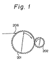
- Figure 1 shows an example of a coil bobbin and driving mechanism according to the related art
- Figs. 2A and 2B respectively show a coil bobbin for explaining problems in the related art
- reference numeral 201 denotes a coil bobbin
- 202 denotes a drive shaft
- 206 denotes a winding wire (coil).
- gear teeth are formed on the outer periphery of the coil bobbin 201 to mesh with a gear of the drive shaft 202, and whereby synchronization of a drive motor and the coil bobbin 201 is established for accurately obtaining the number of turns of the coil unto the fraction. For example, even when the winding start position and the winding end position are offset for 1/4 turn or 1/2 turn, the number of turns of the winding can be accurately obtained up to the fractions of 1/4 and 1/2.
- the shifting magnitude is determined depending upon the diameter of the winding wire 206.
- the diameter of the winding wire 206 may be fluctuated or shifted about ⁇ 20 %.
- a trial winding operation is carried out for fine adjustment of the traverse shifting magnitude so as to obtain an appropriate winding angle, but the fine adjustment cannot be obtained by the diameter fluctuation of the winding wire 206.
- a reversal operation of the traverse shift is carried out by actuating the limit switch with the traverse unit, when the coil (winding wire) 206 abuts the flange at either side end of the coil bobbin 201.
- the gear teeth are formed on the outer periphery of the coil bobbin 201, and thus production cost for the coil bobbin 201 becomes higher and thereby the production cost of the transformer is increased.
- the rotational drive with a meshed gear is not suitable for high speed rotation of the coil bobbin, and thus the meshed gear is not suitable for mass production to again cause a rise in the production cost of the transformer.
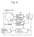
- FIG. 3 is a block diagram showing the basic construction of a transformer coil winding apparatus according to the present invention.
- reference numeral 1 denotes a coil bobbin
- 6 denotes a winding wire (coil)
- 7 denotes a bobbin sensor.
- reference numeral 5 denotes a drive unit
- 8 denotes a traverse unit
- 20 denotes a rotating drive mechanism
- 19 denotes a rotating number counting unit
- 5a denotes rotary encoder.
- the rotating drive mechanism 20 rotatably drives the coil bobbin 1 with the friction force.
- the detection unit for the coil bobbin (bobbin sensor) 7 is provided for the coil bobbin 1.
- the rotating number counting unit 19 counts the number of rotations C1 of the coil bobbin 1 on the basis of the output of the detection unit 7.
- the rotary encoder 5a is, for example, provided on the drive shaft of the rotating drive mechanism 20.
- the drive unit 5 drives the rotating drive mechanism 20 to rotate according to the number of rotations C1 oN the rotating number counting unit 19 and the output C2 of the rotary encoder 5a.
- the winding traverse unit 8 maintains the winding angle of the wire (coil) 6 at a predetermined value. Namely, the winding traverse unit 8 maintains the winding angle of the wire 6 at a predetermined value depending upon the output of the rotary encoder 5a, or in the alternative, the winding angle of the wire 6 is maintained at a predetermined value depending upon the output of a winding angle sensor that detects the winding angle of the wire 6 and is described later in detail.
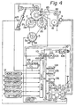
- Figure 4 shows an embodiment of a transformer coil winding apparatus according to the present invention
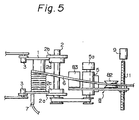
- Fig. 5 shows a plan view of the transformer coil winding apparatus of Fig. 4.
- a coil bobbin 1 is mounted between two pairs of bobbin drive rubber rollers 2a, 2b; 2c, 2d and 2'a, 2'b; 2'c, 2'd which are opposed on a pair of main shafts 2 and 2' at appropriate intervals. Further, the coil bobbin 1 is pressed by a pair of bobbin retainer rollers 3 from the above. Note, motion of the bobbin retainer rollers 3 in an up and down direction can be carried out by a pneumatic cylinder 4. Namely, when the bobbin retainer rollers 3 are lowered, an appropriate friction force is generated between the coil bobbin 1 and the bobbin drive rubber rollers 2a to 2d and 2'a to 2'd by the pressure of the pneumatic cylinder 4.
- the main shafts 2 and 2' are driven by a main shaft driving spindle motor 5 which incorporates an incremental type rotary encoder 5a, and the coil bobbin 1 is driven to rotate and wind the winding wire thereon.
- a traverse unit 8 including a torque control device (not shown) for providing an appropriate tension for the coil is provided for the transformer coil winding apparatus.
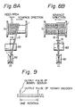
- Figures 6A to 6C show examples of the coil bobbin applying to the transformer coil winding apparatus of the present invention.
- a bobbin sensor 7 is provided for the coil bobbin 1 to detect one cycle of rotation of the coil bobbin 1.
- the coil bobbin 1 comprises two flanges, and these flanges (or coil bobbin 1) are made of dielectric material, such as a plastic.
- the bobbin sensor 7 comprises an optical mark 7a provided on one of the flanges of the coil bobbin 1 and an optical sensor 7b.
- the optical sensor 7b is fixed on the transformer coil winding apparatus and is used to detect the optical mark 7a by one cycle of rotation of the coil bobbin 1.
- the optical mark 7a is formed by a black mark
- the flanges are formed by a white (or light color) coil bobbin, so that the optical sensor 7b can detect the optical mark 7a by the reflection light intensity between the optical mark 7a (small reflection light intensity) and another area (large reflection light intensity) of the flange where the optical mark 7a is not provided.
- the optical mark 7a can be formed by a white mark
- the flanges can be formed by a black (or dark color) coil bobbin.
- the optical mark 7a can be also formed by a specific color mark, for example, red or blue color marks.
- another area of the flange where the optical mark 7a is not provided is formed by another color, for example, green or yellow colors.
- the optical sensor 7b can sense the difference between the colors between the color mark 7a (for example, a red portion) and another area of the flange (for example, a green area). Therefore, the optical sensor 7b can detect the optical mark 7a by one cycle of rotation of the coil bobbin 1.
- the bobbin sensor 7 comprises a metal mark 7'a provided on one of the flanges of the coil bobbin 1 and a metal sensor 7'b.
- the metal sensor 7'b is fixed on the transformer coil winding apparatus and is used to detect the metal mark 7'a by one cycle of rotation of the coil bobbin 1.
- the metal mark 7'a is formed by a metal film for adhering on the flange of the coil bobbin 1 or a metal piece for fitting into the flange of the coil bobbin 1.
- the metal sensor 7'b is, for example, a magnet sensor for enabling to detect the metal mark.
- a sensitive of the metal sensor 7'b is specified to a low value, or the fixed portion of the metal sensor 7'b is located at some distance from the coil bobbin 1, to avoid an erroneous detection of the winding wire (metal wire) 6 which is wound on the coil bobbin 1. Therefore, the metal sensor 7'b can detect the metal mark 7'a by one cycle of rotation of the coil bobbin 1.
- optical marks 7a are provided on the flange of the coil bobbin 1 as a plural.
- the optical mark 7a provided on the flange (with reference to Fig. 6A) is not limited by one, but a plurality of optical marks 7a can be provided on the flange.
- the optical sensor 7b detects four optical marks 7a per one cycle of the coil bobbin 1.
- the metal mark 7'a provided on the flange (with reference to Fig. 6B) is not limited by one, but a plurality of metal marks 7'a can be also provided on the flange.
- At least one optical marks 7a or at least one metal marks 7'a can be provided on the the flange of the coil bobbin 1.
- a plural numbers corresponding to the optical marks 7a or the metal marks 7'a are detected by each one rotation cycle of the coil bobbin 1.
- the optical mark 7a is formed as a rectangular shape
- the metal mark 7'a is formed as a circle shape, but the shapes of the marks 7a and 7'a are not limited by the rectangular and circle shapes and can be formed as various shapes.
- Figure 7 shows a perspective view of an example of a winding angle sensor applying to the transformer coil winding apparatus of the present invention.
- the traverse unit 8 includes a tension wheel 81 (which is shown in Fig. 4) controlled by the torque control device, a reference roller 82 and a winding angle sensor 83 for detecting the winding angle of the winding wire 6.
- the reference roller 82 and the winding angle sensor 83 are driven by a ball screw 11 with a traverse drive motor (stepping motor) 9. Therefore, alignment winding to wind the winding wire for each layer, can be carried out.
- a leaf spring 84 is provided on the shaft of the winding angle sensor 83, and a winding wire guide chip 85 having a V-shaped groove is provided at the tip end.
- the winding wire 6 extends through the V-shaped groove of the reference roller 82 and further through the V-shaped groove of the guide chip 85, and then the winding wire 6 is supplied to the coil bobbin 1.
- Figures 8A and 8B show plan views of a coil bobbin for explaining operations of the traverse unit applying to the transformer coil winding apparatus of the present invention.
- the winding wire 6 becomes, as shown in Figs. 8A and 8B, oriented with respect to the line L defined by the center of the reference roller 82 and the axial center of the winding angle sensor 83, in angle + ⁇ (Fig. 8A) or - ⁇ (Fig. 8B).
- the winding angle sensor 83 desirably has small frictional resistance against rotation and a large output. It is also desirably small and inexpensive.
- the winding angle sensor which employs a non-linear type magnetic resistance element, can be used.
- the control circuit 10 includes an A/D converter 101, an input port 102, a central processing unit (CPU) 103, a ROM 104, a RAM 105, a back-up RAM (b-RAM) 106, an output port 107, and a clock generator 108.
- CPU central processing unit
- ROM read-only memory
- RAM random access memory
- b-RAM back-up RAM
- the A/D converter 101 receives the output of the winding angle sensor 83.
- the output of the counter 109 is input to the input port 102.
- the counter 109 is designed for counting the pulse of the incremental type rotary encoder 5a and is cleared by the output of the bobbin sensor 7, namely every one cycle of rotation of the coil bobbin 1. Further, the counter 109 is also cleared by the CPU 103 as described later.
- the input port 102 receives the output of the bobbin sensor 7, and signals from various switches on a control panel, such as a home-switch 12, a press-switch 13, a start-switch 14, a stop-switch 15, a rightward traverse switch (right-switch) 16, a leftward traverse switch (left-switch) 17, and the like.
- a control panel such as a home-switch 12, a press-switch 13, a start-switch 14, a stop-switch 15, a rightward traverse switch (right-switch) 16, a leftward traverse switch (left-switch) 17, and the like.
- the ROM 104 previously stores the latter described programs, constants and the like, and the RAM 105 also temporarily stores data. Further, in the back-up RAM 106, which is directly connected to a battery (not shown), re-writable data is stored in a non-volatile fashion.
- a D/A converter 110 commanding the speed of the main shaft spindle motor 5 and a driver circuit 111 for the main shaft spindle motor 5 are connected to the output port 107.
- the driver circuit 111 includes a comparator for comparing the output of the D/A converter 110 and a voltage determined by a variable resistor 18 which sets a maximum speed. When the output of the D/A converter 110 is smaller than the maximum speed value, the main shaft spindle motor 5 is driven at a steep corresponding to the output of the D/A converter 110. On the other hand, when the output of the D/A converter 110 is greater than the maximum speed value, the main shaft spindle motor 5 is driven at a speed of the maximum speed value.
- the output port 107 is also connected to a rate generator 112 which generates one pulse per given number of pulses of the incremental type rotary encoder 5a, and a driver circuit 113.
- the given number of pulses is preliminary set in the rate generator 112 by the CPU 103.
- the driver circuit 113 drives the stepping motor 9 in left hand direction or in the right hand direction depending upon the number of pulses from the rate generator 112 in response to the rotating direction command signal from the output port 107.
- the operation of the rate generator 112 can be done by software.
- interruption of the CPU 103 is taken place at a timing after A/D conversion of the A/D converter 101, upon reception of the output of the bobbin sensor 7, a predetermined time interval of the clock generator circuit 107, e.g., upon receipt of a pulse signal every 4 ms.
- the bobbin sensor 7 generates one pulse per every one cycle of rotation of the coil bobbin 1.
- control circuit of Fig. 4 In advance of initiating (turning ON) operation of the control circuit 10, preparation is carried out for setting mechanical conditions, such as the widths of the bobbin driving rubber rollers corresponding to the dimension of the coil bobbin, setting the pressure for the bobbin retainer roller 3, adjustment of an angle of a core receptacle, setting of the winding wire, setting of the torque of the torque control device, setting of variable resistor for the maximum speed of the main shaft 2, 2'.
- mechanical conditions such as the widths of the bobbin driving rubber rollers corresponding to the dimension of the coil bobbin, setting the pressure for the bobbin retainer roller 3, adjustment of an angle of a core receptacle, setting of the winding wire, setting of the torque of the torque control device, setting of variable resistor for the maximum speed of the main shaft 2, 2'.
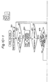
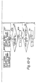
- Figure 10 shows a main routine, which is initiated in response to turning ON a power switch (not shown).
- the main routine is an idle loop including an initialization routine step 801, and steps 802 to 811 for responding to various switches 12 to 15.
- the code number of the bobbin to be used is entered through a keyboard (not shown). Based on the entered code number, the data representative of the above-mentioned electric condition, such as number of coil, number of turns to wind for each coil, winding wire diameter (in this case, nominal wire diameter, winding start portion, winding end position, slow start winding number for winding over which winding is to be carried out at a low speed, ratio relative to the maximum speed for winding at a low speed at both ends of the coil bobbin (%), the reversal angular variation ( ⁇ min ) at both ends of the bobbin, the holding winding angle ( ⁇ R ), degree of slowing down at stopping, and so forth, are transferred to the RAM 105. Also, initialization (clear) of the counter C1 of the RAM and so forth. Furthermore, number n of pulses of the incremental type rotary encoder 5a per pulse of the stepping motor 9 is previously calculated.
- winding wire diameter in this case, nominal wire diameter, winding start portion, winding end
- step 802 judgement is made whether the home-switch 12 is ON or not. Only when the home-switch 12 is ON, the process is advanced to the step 803 to shift the traverse unit 8 to the winding start position by means of the stepping motor 9. When the home-switch 12 is OFF as checked at the step 802, the process is directly advanced to the step 804. In should be noted that, at the OFF position of the home-switch 12, the end of the winding wire (electric wire) 6 is engaged to the coil bobbin.
- the rightward traverse switch (right-switch) 16 or the leftward traverse switch (left-switch) 17 is turned on to adjust the position of the traverse unit 8 through a routine (which is not shown).
- a check is carried out to determine whether the press-switch 13 is ON or not. Only when the press-switch 13 is ON, the process is advanced to a step 805 to determine whether the bobbin retainer roller 3 is depressed onto the coil bobbin 1 with a predetermined pressure. Namely, the press switch 13 is used for urging the bobbin retainer roller 3 onto the coil bobbin 1 (setting) and for releasing it from the coil bobbin 1 (release). Accordingly, in response to the first switching of the press switch 13 to ON, the bobbin retainer roller 3 is depressed onto the coil bobbin 1, and in response to the second switching of the press switch 13 to ON, the bobbin retainer roller 3 is released from the coil bobbin 1.
- the process is advanced to a step 806 to drive the bobbin retainer roller 3 onto the coil bobbin 1 to be depressed thereonto. Conversely, when it is determined that the bobbin retainer roller 3 is depressed onto the coil bobbin 1, the process is advanced to the step 807 to drive the coil retainer roller 3 away from the coil bobbin 1 to release.
- the press switch 13 is OFF as checked at the step 804, the process is directly advanced to the step 808.
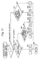
- FIG. 11 shows the routine for controlling the main shaft driving spindle motor 5, which is executed'at predetermined time intervals, e.g., every four milli seconds (4 ms).
- a step 901 it is determined whether the main shaft motor ON flag FX is "1" (main shaft ON control) or "0" (main shaft OFF control).
- FX "1”
- step 902 it is determined whether the winding start position is within a slow start range (C1 ⁇ C (slow start winding number) for the initial stage of winding or not based on the winding number counter C1 of the coil bobbin calculated through the routine which will be discussed later.
- step 903 it is determined whether the value of the winding number counter C1 represents both end regions of the coil bobbin 1.
- a slow start speed SP1 is provided to the driver circuit 111 through the D/A converter 110 as the speed SP of the main shaft driving spindle motor 5, at the step 904.
- a lower speed SP2 which is a given ratio (%) to the maximum speed SPMAX
- the driver circuit 111 is provided through the D/A converter 110 as the speed SP of the main shaft driving spindle motor 5 at a step 905.
- the maximum speed SPMAX is provided for the driver circuit 111 via the D/A converter 110 as the speed SP of the main shaft driving spindle motor 5, at a step 906.
- the maximum speed SPMAX is defined by the variable resistor 18, the command which the CPU 103 provides to the D/A converter 110, is of sufficiently greater value than the SPMAX in practice, at a step 906.
- step 907 it is determined whether the number of windings reaches the predetermined number upon turning of the main shaft and the turn ON flag FX is reset to "0". Until the number of windings reaches the predetermined number, the speed SP of the main shaft driving spindle motor 5 is set at the low speed SP2 at the step 908. When the predetermined number of turns is reached, the speed SP of the main shaft driving spindle motor 5 is set to 0 to stop the motor, at a step 909. Namely, when the main shaft motor ON flag FX is switched from "1" to "0", stopping of the main shaft driving spindle motor 5 is carried out for moderately stopping the same. Then, at the step 910, this routine is terminated.
- Figure 9 shows an example of an output of a bobbin sensor and the output of an incremental type rotary encoder applying to the transformer coil winding apparatus of the present invention.
- the relationship between the number of the output pulse of the bobbin sensor 7 and that of the rotary encoder 5a is maintained at a specific constant value.
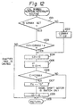
- Figure 12 shows an interrupt routine to be executed at every occurrence of an output of the bobbin sensor 7, and namely every one cycle of rotation of the coil bobbin 1.
- the maximum output number C2MAX of the incremental type rotary encoder 5a is set. Namely, at the step 1001, it is determined whether the value C2MAX has already been set or not. Only when the value C2MAX is not set, the value C2 of the counter 109 is set as the value C2MAX, at a step 1002.
- C2 ⁇ C2MAX - ⁇ it is regarded that chattering is caused in the bobbin sensor 7. Then, the process jumps to a step 1009. It may be possible to generate an alarm at the occurrence of chattering.
- the value C2 of the counter 109 is cleared.
- the counter C1 is counted up by + 1.
- Figure 13 shows a routine for processing the output of the encoder, namely the value C2 of the counter 109.
- the shown routine is executed at every predetermined timing, e.g., every four milli seconds (4 ms).
- the value C2 of the counter is read out.
- the shifting of the traverse unit 8 is controlled depending upon the value C2. Further discussion for the step 1102 will be given later.
- steps 1103 to 1105 are provided for compensating when the output of the bobbin sensor 7 is not generated due to failure. Namely, at a step 1103, when the value C2 of the counter 109 is greater than a value C2MAX + ⁇ which is greater than the set output number C2MAX of the coil bobbin 1, it is regarded that the failure occurs on the output of the bobbin sensor 7.
- the winding counter C1 is incremented by + 1, and at a step 1105, the value C2 of the counter 109 is cleared. Note, it is possible to generate an alarm at this instance. Then, the routine is terminated at a step 1106.
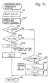
- Figure 14 shows a detailed routine of the traverse shift control step 1102 of Fig. 13.
- the increment value ⁇ C2 of the output number C2 of the encoder is calculated by: ⁇ C2 ⁇ C2 - C2 0 ; where, C2 0 is the immediately preceding value of the value C2.
- the value C2 of the counter 109 is set as the preceding cycle value C2 0 .
- Figures 15 to 17 show the condition in which the winding start position and the winding end position on the coil bobbin 1 are different, namely, a difference is present between the winding start position and the winding end position.
- the OFF control of the main shaft driving spindle motor 5 is defined by the value C1MAX of the winding number counter 19 and the value C2s of the counter 109. Accordingly, in the routine of Fig. 15, the steps 1006 to 1008 of Fig. 12 are not provided, and instead, the steps 1401 to 1404 of Fig. 16 are provided. Also, the traverse shift control step 1102' is differentiated from the traverse shift control step 1102 of Fig. 13, accordingly, the routines of Figs, 14 and 17 are differentiated from each other.
- a check is carried out to determine whether the winding number counter 19 reaches the predetermined value C1MAX.
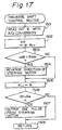
- Figure 17 shows the flowchart showing a detailed process of the traverse shift controlling state 1102' of Fig. 16.
- the traverse shift control is carried out employing the routine of Fig. 17 instead of the routine of Fig. 14.
- the winding angle ⁇ of the winding angle sensor 83 is read out through the A/D converter. Then, at a step 1502, the variation magnitude ⁇ ⁇ of the winding angle ⁇ is calculated by: ⁇ ⁇ ⁇ ⁇ - ⁇ i-1 ; where, ⁇ i-1 is the immediately preceding value of the winding angle ⁇ .
- a step 1503 it is determined whether the absolute value
- the steady state operation of the stepping motor 9 is carried out. namely, at the step 1506, it is determined whether the absolute value
- the steps 1506 and 1507 can perform a reversal of traverse shift in a relatively more stable state than the steps 1206 and 1207 of Fig. 14, because the reversal of traverse in the steps 1206 and 1207 depend upon the diameter of the winding wire.
- the traverse shifting in the step 1503 of Fig. 17 is in response to abrupt variation of the winding angle ⁇ , it is possible to add a condition to determine whether the winding number reaches a value slightly smaller than the winding counter value C1 at the reversal.
- the increment type rotary encoder is employed, however, it is possible to employ an absolute type rotary encoder.
- the counter 109 of Fig. 4 becomes unnecessary and the output per se of the rotary encoder represents the value C2 (only for specific code).
- the coil bobbin production cost can be lowered by employment of the frictional rotation mechanism. Also, it makes it possible to perform a coil winding operation at high speed to contribute to mass production. Therefore, the production cost for the transformer can be lowered. Further, the traverse shift can be done stably, and it allows for the stable reversal of a traverse shift.
Landscapes
- Engineering & Computer Science (AREA)
- Power Engineering (AREA)
- Manufacturing & Machinery (AREA)
- Coil Winding Methods And Apparatuses (AREA)
- Winding Of Webs (AREA)
Claims (15)
- Appareil de bobinage de transformateur pour bobiner un fil de bobinage (6) sur une bobine (1), caractérisé en ce que ledit appareil de bobinage de transformateur comprend :dans lequel ledit moyen pour traverser le bobinage comprend :un mécanisme d'entraínement rotatif (2a à 2d, 2'a à 2'd, 3) pour entraíner de manière rotative ladite bobine (1) par une force de friction entre ladite bobine (1) et ledit mécanisme d'entraínement rotatif (2c, 2'c ; 2d, 2'd),un moyen de détection (7) monté sur ladite bobine (1),un moyen de comptage du nombre de rotations (19) pour compter le nombre de rotations (C1) de ladite bobine (1) sur la base de la sortie dudit moyen de détection (7),un moyen pour traverser le bobinage (8, 9, 11) pour maintenir un angle de bobinage dudit fil de bobinage (6) à une valeur prédéterminée en réponse au nombre de rotations (C1) dudit moyen de comptage du nombre de rotations (19),un capteur d'angle de bobinage (83) pour détecter ledit angle de bobinage dudit fil de bobinage (6), etun moyen de décalage pour traverser le bobinage (9, 11) pour maintenir ledit angle de bobinage détecté à une valeur prédéterminée.
- Appareil de bobinage de transformateur selon la revendication 1 comprenantun codeur rotatif (5a) monté sur un arbre d'entraínement dudit mécanisme d'entraínement rotatif etun moyen d'entraínement (5) pour entraíner de manière rotative ledit mécanisme d'entraínement rotatif (2a à 2d, 2'a à 2'd) en réponse au nombre de rotations (C1) sur ledit moyen de comptage du nombre de rotations (19) et la sortie (C2) dudit codeur rotatif.
- Appareil de bobinage de transformateur pour bobiner un fil de bobinage (6) sur une bobine (1), caractérisé en ce que ledit appareil de bobinage de transformateur comprend :dans lequel ledit moyen pour traverser le bobinage comprend de plus :un mécanisme d'entraínement rotatif (2a à 2d, 2'a à 2'd, 3) pour entraíner de manière rotative ladite bobine (1) par une force de friction entre ladite bobine (1) et ledit mécanisme d'entraínement rotatif (2c, 2'c ; 2d, 2'd),un moyen de détection (7) monté sur ladite bobine (1),un moyen de comptage du nombre de rotations (19) pour compter le nombre de rotations (C1) de ladite bobine (1) sur la base de la sortie dudit moyen de détection (7),un codeur rotatif (5a) monté sur un arbre d'entraínement dudit mécanisme d'entraínement rotatif etun moyen d'entraínement (5) pour entraíner de manière rotative ledit mécanisme d'entraínement rotatif (2a à 2d, 2'a à 2'd) en réponse au nombre de rotations (C1) sur ledit moyen de comptage du nombre de rotations (19) et la sortie (C2) dudit codeur rotatif.un moyen pour traverser le bobinage (8, 9, 11) comprenant un moyen de décalage pour traverser le bobinage (9, 11) pour maintenir un angle de bobinage dudit fil de bobinage (6) à une valeur prédéterminée en réponse au nombre de rotations (C1) sur ledit moyen de comptage du nombre de rotations (19) et la sortie (C2) dudit codeur rotatif (5a),un capteur d'angle de bobinage (83) pour détecter ledit angle de bobinage dudit fil de bobinage (6).
- Appareil de bobinage de transformateur selon l'une des revendications 1 à 3 comprenant de plusun moyen d'évaluation de variation brusque d'angle de bobinage pour évaluer la variation brusque de l'angle de bobinage détecté () etun moyen d'inversion pour inverser ledit angle de bobinage () par ledit moyen de décalage pour traverser le bobinage (9, 11) lorsque ledit angle de bobinage détecté () est modifié brusquement.
- Appareil de bobinage de transformateur selon l'une des revendications 2 à 4 comprenant de plusun moyen. à mémoire (105, 106) pour stocker le nombre de sorties (C2MAX) par cycle dudit codeur rotatif (5a) dans une période de détection pour détecter un cycle de ladite bobine (1) par ledit moyen de comptage du nombre de rotations (19) etun moyen d'inhibition (103) pour inhiber l'incrémentation du compteur du nombre de rotations dudit moyen de comptage du nombre de rotations (19), lorsque le nombre de sorties (C2) ou la valeur de sortie dudit codeur rotatif (5a) à la réception du signal de sortie dudit moyen de détection (7) est inférieur(e) à une valeur (C2MAX-α) inférieure au nombre de sortie (C2MAX) ou à la valeur de sortie par cycle.
- Appareil de bobinage de transformateur selon l'une des revendications 2 à 4 comprenant de plusun moyen à mémoire (105, 106) pour stocker le nombre de sorties (C2MAX) par cycle dudit codeur rotatif (5a) dans une période de détection pour détecter un cycle de ladite bobine (1) par ledit moyen de comptage du nombre de rotations (19) etun moyen de correction du nombre de rotations (103) pour incrémenter le compteur du nombre de rotations dudit moyen de comptage du nombre de rotations (19) de un lorsque le nombre de sorties (C2) ou la valeur de sortie dudit codeur rotatif (5a) à la réception du signal de sortie dudit moyen de détection (7) est supérieur(e) à une valeur (C2MAX+β) supérieure au nombre de sortie (C2MAX) ou à la valeur de sortie par cycle.
- Appareil de bobinage de transformateur selon l'une des revendications 1 à 6, caractérisé en ce que ledit mécanisme d'entraínement rotatif comprend deux paires de galets d'entraínement de bobine (2a, 2b, 2c, 2d ; 2a', 2b', 2c', 2d'), une paire de galets de retenue de bobine (3), et un moyen de déplacement des galets de retenue (4) pour déplacer lesdits galets de retenue de bobine (3) dans des directions montante et descendante.
- Appareil de bobinage de transformateur selon la revendication 7, caractérisé en ce qu'une force de friction appropriée entre ladite bobine (1) et lesdits galets d'entraínement de bobine (2a, 2b, 2c, 2d ; 2a', 2b', 2c', 2d') est générée par la pression dudit moyen de déplacement des galets de retenue (4) lorsque lesdits galets de retenue de bobine (3) sont abaissés.
- Appareil de bobinage de transformateur selon la revendication 7 ou 8, caractérisé en ce que ledit moyen de déplacement des galets de retenue comprend un cylindre pneumatique (4).
- Appareil de bobinage de transformateur selon l'une des revendications 7 à 9, caractérisé en ce que le mécanisme d'entraínement comprend de plus une paire de galets de maintien (2a, 2b) agissant dans la direction de l'arbre sur la bobine (1) et maintenant de manière rotative ladite bobine (1).
- Appareil de bobinage de transformateur selon l'une des revendications 1 à 10, caractérisé en ce que ladite bobine (1) comprend deux flasques et en ce que le moyen de détection (7) comprend au moins un repère optique (7a) gravé sur l'une des deux flasques et un capteur optique (7b) pour détecter ledit repère optique (7a) par un cycle de rotation de ladite bobine.
- Appareil de bobinage de transformateur selon la revendication 11, caractérisé en ce que chacun desdits repères optiques (7a) a un coefficient de réflexion de lumière différent d'une autre zone de ladite flasque où lesdits repères optiques ne sont pas gravés et en ce que ledit capteur optique (7b) détecte l'intensité lumineuse réfléchie par lesdits repères optiques (7a).
- Appareil de bobinage de transformateur selon la revendication 11, caractérisé en ce que chacun desdits repères optiques (7a) a une couleur spécifique différente d'une autre zone de ladite flasque où lesdits repères optiques (7a) ne sont pas gravés et en ce que ledit capteur optique (7b) détecte la couleur desdits repères optiques (7a).
- Appareil de bobinage de transformateur selon l'une des revendications 1 à 10, caractérisé en ce que ladite bobine (1) comprend deux flasques en matériau diélectrique et en ce que ledit moyen de détection (7) comprend au moins un repère métallique (7'a) gravé sur l'une desdites flasques et un capteur de métal (7'b) pour détecter ledit repère métallique (7'a) par un cycle de rotation de ladite bobine.
- Appareil de bobinage de transformateur selon la revendication 14, caractérisé en ce que ledit capteur de métal (7'b) comprend un capteur magnétique.
Applications Claiming Priority (3)
| Application Number | Priority Date | Filing Date | Title |
|---|---|---|---|
| JP27542091 | 1991-10-23 | ||
| JP3275420A JP2953833B2 (ja) | 1991-10-23 | 1991-10-23 | 変圧器用巻線装置 |
| JP275420/91 | 1991-10-23 |
Publications (3)
| Publication Number | Publication Date |
|---|---|
| EP0538545A2 EP0538545A2 (fr) | 1993-04-28 |
| EP0538545A3 EP0538545A3 (en) | 1993-07-07 |
| EP0538545B1 true EP0538545B1 (fr) | 2002-06-12 |
Family
ID=17555263
Family Applications (1)
| Application Number | Title | Priority Date | Filing Date |
|---|---|---|---|
| EP92105475A Expired - Lifetime EP0538545B1 (fr) | 1991-10-23 | 1992-03-30 | Dispositif de bobinage d'une bobine de transformateur pour l'énroulement de fil sur un corps de bobine, permettant de compter correctement le nombre de spires et de bobiner à grande vitesse |
Country Status (9)
| Country | Link |
|---|---|
| US (1) | US5310125A (fr) |
| EP (1) | EP0538545B1 (fr) |
| JP (1) | JP2953833B2 (fr) |
| KR (1) | KR960009073B1 (fr) |
| CN (2) | CN1046816C (fr) |
| CA (1) | CA2064439C (fr) |
| DE (1) | DE69232637T2 (fr) |
| MX (1) | MX9201716A (fr) |
| SG (1) | SG46998A1 (fr) |
Cited By (2)
| Publication number | Priority date | Publication date | Assignee | Title |
|---|---|---|---|---|
| CN101401176B (zh) * | 2006-04-21 | 2012-01-04 | 日本萨比克株式会社 | 绕线机 |
| CN104752050A (zh) * | 2013-12-25 | 2015-07-01 | 特变电工沈阳变压器集团有限公司 | 一种变压器线圈用可调绕线模具扩大变径范围的方法 |
Families Citing this family (14)
| Publication number | Priority date | Publication date | Assignee | Title |
|---|---|---|---|---|
| ES2116168B1 (es) * | 1994-08-25 | 1999-03-01 | Aguilera Gonzalez Francisco | Maquina bobinadora automatica de cables desmagnetizadores para aparatos de television. |
| JP2008148470A (ja) * | 2006-12-12 | 2008-06-26 | Hitachi Ltd | 集中巻コイルおよび集中巻きコイルの製造方法 |
| JP5680977B2 (ja) * | 2011-01-14 | 2015-03-04 | 日特エンジニアリング株式会社 | コイル巻線装置及びコイル巻線方法 |
| US9908756B2 (en) * | 2012-09-28 | 2018-03-06 | Parker-Hannifin Corporation | Constant pull winch controls |
| US9988248B2 (en) * | 2014-04-04 | 2018-06-05 | David R. Hall | Accurate position tracking for motorized lifting device |
| CN103971921A (zh) * | 2014-05-19 | 2014-08-06 | 苏州上电科电气设备有限公司 | 一种变压器绕线机夹具 |
| CN109775443B (zh) * | 2017-11-10 | 2022-01-04 | 苏州凌犀物联网技术有限公司 | 一种机头初始定位装置和初始定位方法 |
| CN108597851B (zh) * | 2018-03-29 | 2023-10-20 | 北华大学 | 一种可调变压器绕线模 |
| WO2020101651A1 (fr) * | 2018-11-13 | 2020-05-22 | Halliburton Energy Services, Inc. | Commande automatique de bobinage de fil |
| CN110632539B (zh) * | 2019-09-27 | 2021-08-17 | 张英华 | 一种电磁铁磁性大小相关因素检测设备 |
| CN112563019B (zh) * | 2020-12-08 | 2022-05-13 | 湖南承运机电有限公司 | 一种带脱卷功能的绕卷装置 |
| CN114203440B (zh) * | 2021-12-15 | 2023-09-29 | 合肥市菲力克斯电子科技有限公司 | 一种电子变压器生产用多角度自动绕线机构 |
| CN114400141B (zh) * | 2022-01-21 | 2025-01-07 | 新华都特种电气股份有限公司 | 变压器绕组生产设备及变压器绕组生产设备的控制方法 |
| CN116031062B (zh) * | 2023-03-14 | 2025-04-25 | 苏州东菱振动试验仪器有限公司 | 一种线圈绕制结构 |
Citations (1)
| Publication number | Priority date | Publication date | Assignee | Title |
|---|---|---|---|---|
| US4629145A (en) * | 1986-03-28 | 1986-12-16 | Essex Group, Inc. | Control of traversing guide in strand winding apparatus |
Family Cites Families (15)
| Publication number | Priority date | Publication date | Assignee | Title |
|---|---|---|---|---|
| GB687151A (en) * | 1950-01-20 | 1953-02-11 | English Electric Co Ltd | Improvements in or relating to coil formers |
| US3462091A (en) * | 1968-03-08 | 1969-08-19 | Gen Electric | Cross wound coil winding machine |
| DE2106258C3 (de) * | 1971-02-10 | 1979-11-08 | Philips Patentverwaltung Gmbh, 2000 Hamburg | Verfahren zum Wickeln einer Übertragerspule und Vorrichtung zur Durchführung dieses Verfahrens |
| FR2263970B1 (fr) * | 1974-03-13 | 1980-06-20 | Stein Kg Drahtzug Drahtfab | |
| JPS5823728B2 (ja) * | 1977-09-02 | 1983-05-17 | 株式会社日立製作所 | トロイダル巻線装置 |
| JPS5842101B2 (ja) * | 1978-05-31 | 1983-09-17 | 株式会社日立製作所 | 整列巻線方法およびその装置 |
| DE2830644C2 (de) * | 1978-07-10 | 1982-09-09 | Siemens AG, 1000 Berlin und 8000 München | Verfahren zum Wickeln elektrischer Spulen |
| US4170951A (en) * | 1978-12-14 | 1979-10-16 | The Singer Company | Skipped stitch detection system |
| JPS55120120A (en) * | 1979-03-10 | 1980-09-16 | Teruo Takahashi | Method for winding wire into tube in loop shape |
| DE3049404C2 (de) * | 1980-12-23 | 1982-09-09 | Siemens AG, 1000 Berlin und 8000 München | Verfahren zum Wickeln elektrischer Spulen |
| JPS5812426A (ja) * | 1981-07-15 | 1983-01-24 | Nec Corp | アナログ・デイジタル変換器の試験装置 |
| JPS62264610A (ja) * | 1986-05-13 | 1987-11-17 | Mitsubishi Electric Corp | コイルの巻線方法 |
| JP2604029B2 (ja) * | 1989-02-17 | 1997-04-23 | 株式会社ミツバ | 巻線用張力発生装置 |
| JP2716786B2 (ja) * | 1989-03-22 | 1998-02-18 | 株式会社ミツバ | モータ回転子の巻線状態検出装置 |
| JP2518075B2 (ja) * | 1989-04-28 | 1996-07-24 | 三菱電機株式会社 | ワイヤ放電加工装置のワイヤ電極供給装置 |
-
1991
- 1991-10-23 JP JP3275420A patent/JP2953833B2/ja not_active Expired - Fee Related
-
1992
- 1992-03-27 US US07/859,333 patent/US5310125A/en not_active Expired - Lifetime
- 1992-03-30 CN CN92103120A patent/CN1046816C/zh not_active Expired - Lifetime
- 1992-03-30 DE DE69232637T patent/DE69232637T2/de not_active Expired - Fee Related
- 1992-03-30 EP EP92105475A patent/EP0538545B1/fr not_active Expired - Lifetime
- 1992-03-30 SG SG1996001327A patent/SG46998A1/en unknown
- 1992-03-30 CA CA002064439A patent/CA2064439C/fr not_active Expired - Fee Related
- 1992-03-31 KR KR92005367A patent/KR960009073B1/ko not_active Expired - Fee Related
- 1992-04-13 MX MX9201716A patent/MX9201716A/es not_active IP Right Cessation
- 1992-08-15 CN CN92230822U patent/CN2153128Y/zh not_active Expired - Lifetime
Patent Citations (1)
| Publication number | Priority date | Publication date | Assignee | Title |
|---|---|---|---|---|
| US4629145A (en) * | 1986-03-28 | 1986-12-16 | Essex Group, Inc. | Control of traversing guide in strand winding apparatus |
Cited By (2)
| Publication number | Priority date | Publication date | Assignee | Title |
|---|---|---|---|---|
| CN101401176B (zh) * | 2006-04-21 | 2012-01-04 | 日本萨比克株式会社 | 绕线机 |
| CN104752050A (zh) * | 2013-12-25 | 2015-07-01 | 特变电工沈阳变压器集团有限公司 | 一种变压器线圈用可调绕线模具扩大变径范围的方法 |
Also Published As
| Publication number | Publication date |
|---|---|
| KR960009073B1 (en) | 1996-07-10 |
| SG46998A1 (en) | 1998-03-20 |
| CA2064439A1 (fr) | 1993-04-24 |
| US5310125A (en) | 1994-05-10 |
| CN2153128Y (zh) | 1994-01-12 |
| MX9201716A (es) | 1994-05-31 |
| DE69232637T2 (de) | 2004-05-13 |
| EP0538545A2 (fr) | 1993-04-28 |
| CN1046816C (zh) | 1999-11-24 |
| CN1071781A (zh) | 1993-05-05 |
| JP2953833B2 (ja) | 1999-09-27 |
| EP0538545A3 (en) | 1993-07-07 |
| JPH05114528A (ja) | 1993-05-07 |
| KR930008885A (ko) | 1993-05-22 |
| CA2064439C (fr) | 1997-02-25 |
| DE69232637D1 (de) | 2002-07-18 |
Similar Documents
| Publication | Publication Date | Title |
|---|---|---|
| US5310125A (en) | Transformer coil winding apparatus for winding wire on a coil bobbin | |
| US5209414A (en) | Apparatus for precisely winding a coil of wire | |
| EP0078979B1 (fr) | Bobinoir | |
| US20060011775A1 (en) | Reel members and film winding methods | |
| EP0248406B1 (fr) | Appareil de va-et-vient pour fil | |
| US4480799A (en) | Apparatus for controlling tension applied onto an electric wire in a winding machine | |
| US5785265A (en) | Winding machine for a continuously arriving yarn | |
| US4748310A (en) | Wire feed mechanism of wire electric discharge machine | |
| WO1996028304A1 (fr) | Procede pour regler le mecanisme d'enroulement d'un ruban dans un appareil d'impression | |
| HK1010420B (en) | Transformer coil winding apparatus for winding wire on coil bobbin with correctly counting winding number and enabling high speed winding operation | |
| HK1010420A (en) | Transformer coil winding apparatus for winding wire on coil bobbin with correctly counting winding number and enabling high speed winding operation | |
| JP2539756B2 (ja) | 糸条類のスプ―ル巻き方法及び装置 | |
| JPS60218248A (ja) | 粘着テ−プの巻取方法 | |
| JP2919767B2 (ja) | コイル巻線装置 | |
| JP2731253B2 (ja) | 巻線機 | |
| JPH0824092B2 (ja) | リングコア捲線機 | |
| JPH07110741B2 (ja) | 線状体の巻取装置 | |
| JPS60218249A (ja) | 粘着テ−プの巻取方法 | |
| JPH0441802B2 (fr) | ||
| JP2847088B2 (ja) | Sz巻きスロットスペーサ型光ケーブルの製造方法 | |
| JPS6039621B2 (ja) | 線材の整列巻き方法およびその装置 | |
| JPH0726295Y2 (ja) | テープ巻き装置 | |
| JPH0258783A (ja) | テープ巻付装置 | |
| DE3032273A1 (de) | Bandtransportsystem | |
| SU1416422A1 (ru) | Регул тор нат жени длинномерного материала |
Legal Events
| Date | Code | Title | Description |
|---|---|---|---|
| PUAI | Public reference made under article 153(3) epc to a published international application that has entered the european phase |
Free format text: ORIGINAL CODE: 0009012 |
|
| AK | Designated contracting states |
Kind code of ref document: A2 Designated state(s): DE FR GB |
|
| PUAL | Search report despatched |
Free format text: ORIGINAL CODE: 0009013 |
|
| AK | Designated contracting states |
Kind code of ref document: A3 Designated state(s): DE FR GB |
|
| 17P | Request for examination filed |
Effective date: 19930902 |
|
| 17Q | First examination report despatched |
Effective date: 19941129 |
|
| GRAG | Despatch of communication of intention to grant |
Free format text: ORIGINAL CODE: EPIDOS AGRA |
|
| GRAG | Despatch of communication of intention to grant |
Free format text: ORIGINAL CODE: EPIDOS AGRA |
|
| GRAH | Despatch of communication of intention to grant a patent |
Free format text: ORIGINAL CODE: EPIDOS IGRA |
|
| GRAH | Despatch of communication of intention to grant a patent |
Free format text: ORIGINAL CODE: EPIDOS IGRA |
|
| GRAA | (expected) grant |
Free format text: ORIGINAL CODE: 0009210 |
|
| AK | Designated contracting states |
Kind code of ref document: B1 Designated state(s): DE FR GB |
|
| REG | Reference to a national code |
Ref country code: GB Ref legal event code: FG4D |
|
| REF | Corresponds to: |
Ref document number: 69232637 Country of ref document: DE Date of ref document: 20020718 |
|
| ET | Fr: translation filed | ||
| PLBE | No opposition filed within time limit |
Free format text: ORIGINAL CODE: 0009261 |
|
| STAA | Information on the status of an ep patent application or granted ep patent |
Free format text: STATUS: NO OPPOSITION FILED WITHIN TIME LIMIT |
|
| 26N | No opposition filed |
Effective date: 20030313 |
|
| PGFP | Annual fee paid to national office [announced via postgrant information from national office to epo] |
Ref country code: FR Payment date: 20050308 Year of fee payment: 14 |
|
| PGFP | Annual fee paid to national office [announced via postgrant information from national office to epo] |
Ref country code: GB Payment date: 20050330 Year of fee payment: 14 |
|
| PGFP | Annual fee paid to national office [announced via postgrant information from national office to epo] |
Ref country code: DE Payment date: 20050525 Year of fee payment: 14 |
|
| PG25 | Lapsed in a contracting state [announced via postgrant information from national office to epo] |
Ref country code: GB Free format text: LAPSE BECAUSE OF NON-PAYMENT OF DUE FEES Effective date: 20060330 |
|
| PG25 | Lapsed in a contracting state [announced via postgrant information from national office to epo] |
Ref country code: DE Free format text: LAPSE BECAUSE OF NON-PAYMENT OF DUE FEES Effective date: 20061003 |
|
| GBPC | Gb: european patent ceased through non-payment of renewal fee |
Effective date: 20060330 |
|
| REG | Reference to a national code |
Ref country code: FR Ref legal event code: ST Effective date: 20061130 |
|
| PG25 | Lapsed in a contracting state [announced via postgrant information from national office to epo] |
Ref country code: FR Free format text: LAPSE BECAUSE OF NON-PAYMENT OF DUE FEES Effective date: 20060331 |