EP0540946A2 - Méthode pour la transmission digitale d'informations - Google Patents
Méthode pour la transmission digitale d'informations Download PDFInfo
- Publication number
- EP0540946A2 EP0540946A2 EP92118055A EP92118055A EP0540946A2 EP 0540946 A2 EP0540946 A2 EP 0540946A2 EP 92118055 A EP92118055 A EP 92118055A EP 92118055 A EP92118055 A EP 92118055A EP 0540946 A2 EP0540946 A2 EP 0540946A2
- Authority
- EP
- European Patent Office
- Prior art keywords
- control unit
- decision maker
- summing point
- phase shifter
- signals
- Prior art date
- Legal status (The legal status is an assumption and is not a legal conclusion. Google has not performed a legal analysis and makes no representation as to the accuracy of the status listed.)
- Granted
Links
- 230000005540 biological transmission Effects 0.000 title claims abstract description 26
- 238000000034 method Methods 0.000 title claims abstract description 18
- 238000005070 sampling Methods 0.000 claims abstract description 13
- 238000011084 recovery Methods 0.000 claims abstract description 8
- 238000009751 slip forming Methods 0.000 claims abstract 2
- 239000004020 conductor Substances 0.000 claims description 3
- 230000006978 adaptation Effects 0.000 description 2
- 230000003287 optical effect Effects 0.000 description 2
- 230000003044 adaptive effect Effects 0.000 description 1
- 238000003491 array Methods 0.000 description 1
- 230000000712 assembly Effects 0.000 description 1
- 238000000429 assembly Methods 0.000 description 1
- 230000015572 biosynthetic process Effects 0.000 description 1
- 238000013461 design Methods 0.000 description 1
- 238000011156 evaluation Methods 0.000 description 1
- 230000006870 function Effects 0.000 description 1
- 238000004519 manufacturing process Methods 0.000 description 1
- 230000015654 memory Effects 0.000 description 1
- 238000012545 processing Methods 0.000 description 1
- 230000008054 signal transmission Effects 0.000 description 1
- 230000006641 stabilisation Effects 0.000 description 1
- 238000011105 stabilization Methods 0.000 description 1
- 230000002123 temporal effect Effects 0.000 description 1
- 230000036962 time dependent Effects 0.000 description 1
- 238000012546 transfer Methods 0.000 description 1
Images

Classifications
-
- H—ELECTRICITY
- H04—ELECTRIC COMMUNICATION TECHNIQUE
- H04L—TRANSMISSION OF DIGITAL INFORMATION, e.g. TELEGRAPHIC COMMUNICATION
- H04L7/00—Arrangements for synchronising receiver with transmitter
- H04L7/0054—Detection of the synchronisation error by features other than the received signal transition
- H04L7/0062—Detection of the synchronisation error by features other than the received signal transition detection of error based on data decision error, e.g. Mueller type detection
-
- H—ELECTRICITY
- H04—ELECTRIC COMMUNICATION TECHNIQUE
- H04L—TRANSMISSION OF DIGITAL INFORMATION, e.g. TELEGRAPHIC COMMUNICATION
- H04L7/00—Arrangements for synchronising receiver with transmitter
- H04L7/0079—Receiver details
- H04L7/0083—Receiver details taking measures against momentary loss of synchronisation, e.g. inhibiting the synchronisation, using idle words or using redundant clocks
Definitions
- the invention relates to a method for digital message transmission, in which the transmitted signals at the end of the transmission path are sampled by means of a clock recovery device and then further processed and fed to a decision maker (US-Z "IEEE TRANSACTIONS ON COMMUNICATIONS", VOL. COM-35 , NO. 9, September 1987, pages 961 to 968).
- signals via message transmission can be transmitted wired or wirelessly.
- Cables with electrical or optical transmission paths are used for wired transmission.
- the wireless transmission takes place, for example, via radio relay or satellite radio. Varying the transmission function of the transmission channel, for example by changing the length of a cable with metallic conductors, not only changes the shape of the signals received (pulses), but also shifts the temporal position of the respective pulse maximum.
- the entire pulse formation is also influenced by the temperature drift and the tolerances of the components or the cable used in the transmitter and receiver. It is therefore time-dependent and subject to a certain spread. In synchronously operated transmission systems combined in one cable, cyclical stationary faults continue to occur, the performance of which fluctuates periodically over time.
- the time of sampling or the clock phase are generally compared once during the manufacture of the respective assemblies. This means not only additional adjustment work, but the influencing factors described above are only insufficiently or not at all taken into account.
- the invention is based on the object of developing the method described at the outset in such a way that compliance with a permissible bit error rate is ensured and the range of the transmission can be increased.
- a phase shifter is therefore used, which is controlled by a control unit, for example a microcontroller.
- the control unit is supplied with the difference values between the signals at the input of the decision maker on the one hand and at the output thereof on the other hand from the summing point.
- the control unit forms an average value from the difference values supplied to it - for example the quadratic mean value or the mean value value - and after stabilization of the same - adjusts the phase shifter by a predeterminable amount. It is decisive for the point in time of an adjustment of the phase shifter that the system is in the steady state again after an adjustment, so that a stable mean value of the difference values is given.
- the sampling time is therefore constantly adapted to the respective circumstances.
- the method according to the invention can be used both in line-based message transmission via electrical or optical cables and in wireless message transmission.
- the method is of particular importance in the transmission of messages via electrical cables in which symmetrical double cores are combined with metallic conductors.
- the electrical cable is considered as the transmission medium.
- the distorted digital signals superimposed by interference travel from a cable 1 to a receiver 2, which has a reception filter 3, a scanning device 4 and a detector 5.
- a receiver 2 which has a reception filter 3, a scanning device 4 and a detector 5.
- FIG. 2 The more precise design of the receiver 2 is shown in FIG. 2:
- a phase shifter 8 connected to a clock recovery device 7 acts on the A / D converter 6.
- the decision-maker 10 recovers the source signals originally sent from the processed signals supplied by the filter unit 9.
- the input signal ES and output signal AS of the decision maker 10 are fed to a summing point 11.
- the output signal AS of the decision maker 10 can also be given to the filter unit 9 for evaluation.
- the difference signal D generated at the summing point 11 is applied to a control unit 12, which in turn controls the phase shifter 8.
- the amount ⁇ by which the phase shifter 8 is adjusted in each case is to be adapted to the circumstances. It should not be too small, so that the adaptation of the optimal sampling time does not take too long. On the other hand, an excessively large amount .DELTA..phi. Is not sensible, since the adaptation may then constantly oscillate back and forth and the optimum u. U. is not reached.
- the amount ⁇ by which the phase shifter 8 is adjusted remains the same in each case.
- a reasonable amount for ⁇ is, for example, 1% of the total clock phase.
- the amount ⁇ can also be variable. This can be useful if larger deviations occur.
- a further adjustment of the phase shifter 8 can be carried out by the same amount as before.
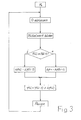
- the new stable mean M (i) is first compared to the previous stable mean M (i - 1) used for adjusting the phase shifter 8. If the new mean M (i) is smaller than the previous one, then the phase of the sampling time was shifted in the correct direction by the amount ⁇ . The next adjustment by the amount ⁇ then takes place in the same direction. If, on the other hand, the new mean M (i) is greater than the previous one, the phase is adjusted in the opposite direction by the amount ⁇ .
- the time of the adjustment can also be specified by the control unit 12. In any case, an adjustment is only made when the system has settled and the respective mean M (i) is stable. Accordingly, there is a pause between two adjustments of the sampling time.
- the filter unit 9 preferably consists of digital filters. Such filters are described, for example, in the DE-Z "FREQUENCY" mentioned at the beginning.
- the decision maker 10 can be a component known in the art of message transmission, such as a comparator or a logic circuit.
- the control unit 12 can be an intelligent module with memories, for example a microprocessor or a microcontroller. However, gate arrays or other logic circuits can also be used.
Landscapes
- Engineering & Computer Science (AREA)
- Computer Networks & Wireless Communication (AREA)
- Signal Processing (AREA)
- Synchronisation In Digital Transmission Systems (AREA)
- Digital Transmission Methods That Use Modulated Carrier Waves (AREA)
- Reduction Or Emphasis Of Bandwidth Of Signals (AREA)
- Communication Control (AREA)
- Noise Elimination (AREA)
- Dc Digital Transmission (AREA)
- Cable Transmission Systems, Equalization Of Radio And Reduction Of Echo (AREA)
- Testing, Inspecting, Measuring Of Stereoscopic Televisions And Televisions (AREA)
Applications Claiming Priority (2)
| Application Number | Priority Date | Filing Date | Title |
|---|---|---|---|
| DE4136474A DE4136474A1 (de) | 1991-11-06 | 1991-11-06 | Verfahren zur digitalen nachrichtenuebertragung |
| DE4136474 | 1991-11-06 |
Publications (3)
| Publication Number | Publication Date |
|---|---|
| EP0540946A2 true EP0540946A2 (fr) | 1993-05-12 |
| EP0540946A3 EP0540946A3 (fr) | 1994-01-19 |
| EP0540946B1 EP0540946B1 (fr) | 1998-01-14 |
Family
ID=6444162
Family Applications (1)
| Application Number | Title | Priority Date | Filing Date |
|---|---|---|---|
| EP92118055A Expired - Lifetime EP0540946B1 (fr) | 1991-11-06 | 1992-10-22 | Méthode pour la transmission digitale d'informations |
Country Status (8)
| Country | Link |
|---|---|
| EP (1) | EP0540946B1 (fr) |
| CN (1) | CN1072301A (fr) |
| AT (1) | ATE162351T1 (fr) |
| CA (1) | CA2081156A1 (fr) |
| DE (2) | DE4136474A1 (fr) |
| DK (1) | DK0540946T3 (fr) |
| ES (1) | ES2111597T3 (fr) |
| IL (1) | IL103624A0 (fr) |
Cited By (4)
| Publication number | Priority date | Publication date | Assignee | Title |
|---|---|---|---|---|
| FR2710219A1 (fr) * | 1993-09-13 | 1995-03-24 | Trt Telecom Radio Electr | Dispositif de récupération du rythme d'horloge et modem comportant un tel dispositif. |
| EP1315304A3 (fr) * | 2001-11-16 | 2004-03-03 | Philips Intellectual Property & Standards GmbH | Récepteur pour signaux de communication |
| AT413252B (de) * | 1997-09-29 | 2005-12-15 | Molisch Andreas F Dr | Verfahren zur bestimmung des optimalen abtastzeitpunktes von digitalen signalfolgen mittels trainingsfolgen |
| EP1318638A3 (fr) * | 2001-11-16 | 2006-05-17 | Philips Intellectual Property & Standards GmbH | Dispositif de réception de signals encodés par transitions avec l'utilisation d'échantillonnage adaptatif |
Family Cites Families (1)
| Publication number | Priority date | Publication date | Assignee | Title |
|---|---|---|---|---|
| JPS62298255A (ja) * | 1986-06-18 | 1987-12-25 | Fujitsu Ltd | 識別装置 |
-
1991
- 1991-11-06 DE DE4136474A patent/DE4136474A1/de not_active Withdrawn
-
1992
- 1992-10-22 AT AT92118055T patent/ATE162351T1/de not_active IP Right Cessation
- 1992-10-22 ES ES92118055T patent/ES2111597T3/es not_active Expired - Lifetime
- 1992-10-22 DK DK92118055.0T patent/DK0540946T3/da active
- 1992-10-22 CA CA002081156A patent/CA2081156A1/fr not_active Abandoned
- 1992-10-22 EP EP92118055A patent/EP0540946B1/fr not_active Expired - Lifetime
- 1992-10-22 DE DE59209132T patent/DE59209132D1/de not_active Expired - Fee Related
- 1992-11-03 IL IL103624A patent/IL103624A0/xx unknown
- 1992-11-06 CN CN92112744.8A patent/CN1072301A/zh active Pending
Cited By (4)
| Publication number | Priority date | Publication date | Assignee | Title |
|---|---|---|---|---|
| FR2710219A1 (fr) * | 1993-09-13 | 1995-03-24 | Trt Telecom Radio Electr | Dispositif de récupération du rythme d'horloge et modem comportant un tel dispositif. |
| AT413252B (de) * | 1997-09-29 | 2005-12-15 | Molisch Andreas F Dr | Verfahren zur bestimmung des optimalen abtastzeitpunktes von digitalen signalfolgen mittels trainingsfolgen |
| EP1315304A3 (fr) * | 2001-11-16 | 2004-03-03 | Philips Intellectual Property & Standards GmbH | Récepteur pour signaux de communication |
| EP1318638A3 (fr) * | 2001-11-16 | 2006-05-17 | Philips Intellectual Property & Standards GmbH | Dispositif de réception de signals encodés par transitions avec l'utilisation d'échantillonnage adaptatif |
Also Published As
| Publication number | Publication date |
|---|---|
| DK0540946T3 (da) | 1998-03-16 |
| ES2111597T3 (es) | 1998-03-16 |
| DE4136474A1 (de) | 1993-05-13 |
| EP0540946B1 (fr) | 1998-01-14 |
| CA2081156A1 (fr) | 1993-05-07 |
| ATE162351T1 (de) | 1998-01-15 |
| IL103624A0 (en) | 1993-04-04 |
| DE59209132D1 (de) | 1998-02-19 |
| EP0540946A3 (fr) | 1994-01-19 |
| CN1072301A (zh) | 1993-05-19 |
Similar Documents
| Publication | Publication Date | Title |
|---|---|---|
| EP0102598B1 (fr) | Dispositif pour la synchronisation de phase | |
| DE3604277C2 (de) | Vorrichtung zum Einstellen der Phasenlage von Datensignalen | |
| DE3687114T2 (de) | Datenuebertragungssystem. | |
| EP0412616B1 (fr) | Récepteur pour signaux de données distordus de façon temporellement variable | |
| DE3242577A1 (de) | Endeinrichtung zur digitalen duplexuebertragung ueber eine zweidrahtleitung | |
| DE2056670A1 (de) | Phasen und amplitudenmodulierter Mo | |
| EP0978176A1 (fr) | Procede de regeneration de donnees | |
| EP0356548B1 (fr) | Procédé et circuit pour contrôler numériquement la fréquence et/ou la phase des impulsions d'une horloge d'échantillonnage | |
| EP1470659A1 (fr) | Procede de regulation de phases d'echantillonnage | |
| DE3927681A1 (de) | Verfahren zur zwischenverstaerkung von digitalen signalen sowie zwischenverstaerker fuer digitale signale | |
| DE68908579T2 (de) | Empfänger für ein Datensymbolübertragungssystem mit vorgegebener Baudgeschwindigkeit. | |
| DE3030811A1 (de) | Raumdiversity-empfaenger mit zf-kombinator | |
| WO1998049811A2 (fr) | Procede et dispositif pour regler le seuil de decision et l'instant d'echantillonnage d'un regenerateur de donnees | |
| DE2619964A1 (de) | Anordnung zur impuls-zeitlagekorrektur | |
| EP0540946B1 (fr) | Méthode pour la transmission digitale d'informations | |
| DE19922804C2 (de) | Taktwiedergewinnungsschaltung | |
| EP0356549B1 (fr) | Procédé et circuit pour contrôler numériquement la phase des impulsions d'une horloge d'échantillonnage | |
| EP0133298A1 (fr) | Procédé et circuit pour la compensation des signaux d'écho | |
| EP0066006B1 (fr) | Montage pour la compensation de la diaphonie et/ou des échos | |
| EP0063638B1 (fr) | Système de télécommunication numérique | |
| DE19612714A1 (de) | Schaltungsanordnung zur Regeneration eines digitale Datenfolgen enthaltenden Eingangssignals | |
| DE60201030T2 (de) | Empfänger mit einer rückgewinnungsschaltung mittels überabtastung und mehrheitsentscheidung | |
| DE3120434A1 (de) | Adaptive echokompensationseinrichtung zur digitalen duplexuebertragung auf zweidrahtleitungen | |
| DE4220557C2 (de) | Verfahren zur digitalen Nachrichtenübertragung | |
| DE2632165A1 (de) | Schaltungsanordnung zum regeln der folgefrequenz von taktimpulsen |
Legal Events
| Date | Code | Title | Description |
|---|---|---|---|
| PUAI | Public reference made under article 153(3) epc to a published international application that has entered the european phase |
Free format text: ORIGINAL CODE: 0009012 |
|
| AK | Designated contracting states |
Kind code of ref document: A2 Designated state(s): AT BE CH DE DK ES FR GB GR IT LI LU NL PT SE |
|
| PUAL | Search report despatched |
Free format text: ORIGINAL CODE: 0009013 |
|
| AK | Designated contracting states |
Kind code of ref document: A3 Designated state(s): AT BE CH DE DK ES FR GB GR IT LI LU NL PT SE |
|
| 17P | Request for examination filed |
Effective date: 19931208 |
|
| 17Q | First examination report despatched |
Effective date: 19960902 |
|
| GRAG | Despatch of communication of intention to grant |
Free format text: ORIGINAL CODE: EPIDOS AGRA |
|
| GRAG | Despatch of communication of intention to grant |
Free format text: ORIGINAL CODE: EPIDOS AGRA |
|
| GRAH | Despatch of communication of intention to grant a patent |
Free format text: ORIGINAL CODE: EPIDOS IGRA |
|
| GRAH | Despatch of communication of intention to grant a patent |
Free format text: ORIGINAL CODE: EPIDOS IGRA |
|
| RAP1 | Party data changed (applicant data changed or rights of an application transferred) |
Owner name: ALCATEL ALSTHOM COMPAGNIE GENERALE D'ELECTRICITE |
|
| GRAA | (expected) grant |
Free format text: ORIGINAL CODE: 0009210 |
|
| AK | Designated contracting states |
Kind code of ref document: B1 Designated state(s): AT BE CH DE DK ES FR GB GR IT LI LU NL PT SE |
|
| PG25 | Lapsed in a contracting state [announced via postgrant information from national office to epo] |
Ref country code: NL Free format text: LAPSE BECAUSE OF FAILURE TO SUBMIT A TRANSLATION OF THE DESCRIPTION OR TO PAY THE FEE WITHIN THE PRESCRIBED TIME-LIMIT Effective date: 19980114 Ref country code: GR Free format text: LAPSE BECAUSE OF FAILURE TO SUBMIT A TRANSLATION OF THE DESCRIPTION OR TO PAY THE FEE WITHIN THE PRESCRIBED TIME-LIMIT Effective date: 19980114 |
|
| REF | Corresponds to: |
Ref document number: 162351 Country of ref document: AT Date of ref document: 19980115 Kind code of ref document: T |
|
| REG | Reference to a national code |
Ref country code: CH Ref legal event code: EP |
|
| ITF | It: translation for a ep patent filed | ||
| GBT | Gb: translation of ep patent filed (gb section 77(6)(a)/1977) |
Effective date: 19980116 |
|
| REF | Corresponds to: |
Ref document number: 59209132 Country of ref document: DE Date of ref document: 19980219 |
|
| ET | Fr: translation filed | ||
| REG | Reference to a national code |
Ref country code: DK Ref legal event code: T3 Ref country code: ES Ref legal event code: FG2A Ref document number: 2111597 Country of ref document: ES Kind code of ref document: T3 |
|
| PG25 | Lapsed in a contracting state [announced via postgrant information from national office to epo] |
Ref country code: PT Free format text: LAPSE BECAUSE OF FAILURE TO SUBMIT A TRANSLATION OF THE DESCRIPTION OR TO PAY THE FEE WITHIN THE PRESCRIBED TIME-LIMIT Effective date: 19980414 |
|
| REG | Reference to a national code |
Ref country code: CH Ref legal event code: NV Representative=s name: CABINET ROLAND NITHARDT CONSEILS EN PROPRIETE INDU |
|
| NLV1 | Nl: lapsed or annulled due to failure to fulfill the requirements of art. 29p and 29m of the patents act | ||
| PG25 | Lapsed in a contracting state [announced via postgrant information from national office to epo] |
Ref country code: LU Free format text: LAPSE BECAUSE OF NON-PAYMENT OF DUE FEES Effective date: 19981022 |
|
| PLBE | No opposition filed within time limit |
Free format text: ORIGINAL CODE: 0009261 |
|
| STAA | Information on the status of an ep patent application or granted ep patent |
Free format text: STATUS: NO OPPOSITION FILED WITHIN TIME LIMIT |
|
| 26N | No opposition filed | ||
| REG | Reference to a national code |
Ref country code: CH Ref legal event code: PFA Free format text: ALCATEL ALSTHOM COMPAGNIE GENERALE D'ELECTRICITE TRANSFER- ALCATEL SOCIETE ANONYME |
|
| PGFP | Annual fee paid to national office [announced via postgrant information from national office to epo] |
Ref country code: GB Payment date: 19990913 Year of fee payment: 8 |
|
| PGFP | Annual fee paid to national office [announced via postgrant information from national office to epo] |
Ref country code: CH Payment date: 19990915 Year of fee payment: 8 |
|
| PGFP | Annual fee paid to national office [announced via postgrant information from national office to epo] |
Ref country code: SE Payment date: 19990920 Year of fee payment: 8 Ref country code: FR Payment date: 19990920 Year of fee payment: 8 Ref country code: DK Payment date: 19990920 Year of fee payment: 8 |
|
| PGFP | Annual fee paid to national office [announced via postgrant information from national office to epo] |
Ref country code: AT Payment date: 19990923 Year of fee payment: 8 |
|
| PGFP | Annual fee paid to national office [announced via postgrant information from national office to epo] |
Ref country code: DE Payment date: 19990927 Year of fee payment: 8 |
|
| PGFP | Annual fee paid to national office [announced via postgrant information from national office to epo] |
Ref country code: BE Payment date: 19990929 Year of fee payment: 8 |
|
| PGFP | Annual fee paid to national office [announced via postgrant information from national office to epo] |
Ref country code: ES Payment date: 19991020 Year of fee payment: 8 |
|
| REG | Reference to a national code |
Ref country code: FR Ref legal event code: CD |
|
| PG25 | Lapsed in a contracting state [announced via postgrant information from national office to epo] |
Ref country code: GB Free format text: LAPSE BECAUSE OF NON-PAYMENT OF DUE FEES Effective date: 20001022 Ref country code: DK Free format text: LAPSE BECAUSE OF NON-PAYMENT OF DUE FEES Effective date: 20001022 Ref country code: AT Free format text: LAPSE BECAUSE OF NON-PAYMENT OF DUE FEES Effective date: 20001022 |
|
| PG25 | Lapsed in a contracting state [announced via postgrant information from national office to epo] |
Ref country code: ES Free format text: LAPSE BECAUSE OF NON-PAYMENT OF DUE FEES Effective date: 20001023 |
|
| PG25 | Lapsed in a contracting state [announced via postgrant information from national office to epo] |
Ref country code: SE Free format text: THE PATENT HAS BEEN ANNULLED BY A DECISION OF A NATIONAL AUTHORITY Effective date: 20001030 |
|
| PG25 | Lapsed in a contracting state [announced via postgrant information from national office to epo] |
Ref country code: LI Free format text: LAPSE BECAUSE OF NON-PAYMENT OF DUE FEES Effective date: 20001031 Ref country code: CH Free format text: LAPSE BECAUSE OF NON-PAYMENT OF DUE FEES Effective date: 20001031 Ref country code: BE Free format text: LAPSE BECAUSE OF NON-PAYMENT OF DUE FEES Effective date: 20001031 |
|
| BERE | Be: lapsed |
Owner name: ALCATEL Effective date: 20001031 |
|
| REG | Reference to a national code |
Ref country code: DK Ref legal event code: EBP |
|
| GBPC | Gb: european patent ceased through non-payment of renewal fee |
Effective date: 20001022 |
|
| REG | Reference to a national code |
Ref country code: CH Ref legal event code: PL |
|
| EUG | Se: european patent has lapsed |
Ref document number: 92118055.0 |
|
| PG25 | Lapsed in a contracting state [announced via postgrant information from national office to epo] |
Ref country code: FR Free format text: LAPSE BECAUSE OF NON-PAYMENT OF DUE FEES Effective date: 20010629 |
|
| PG25 | Lapsed in a contracting state [announced via postgrant information from national office to epo] |
Ref country code: DE Free format text: LAPSE BECAUSE OF NON-PAYMENT OF DUE FEES Effective date: 20010703 |
|
| REG | Reference to a national code |
Ref country code: FR Ref legal event code: ST |
|
| REG | Reference to a national code |
Ref country code: ES Ref legal event code: FD2A Effective date: 20011113 |
|
| PG25 | Lapsed in a contracting state [announced via postgrant information from national office to epo] |
Ref country code: IT Free format text: LAPSE BECAUSE OF NON-PAYMENT OF DUE FEES;WARNING: LAPSES OF ITALIAN PATENTS WITH EFFECTIVE DATE BEFORE 2007 MAY HAVE OCCURRED AT ANY TIME BEFORE 2007. THE CORRECT EFFECTIVE DATE MAY BE DIFFERENT FROM THE ONE RECORDED. Effective date: 20051022 |