EP0544576A1 - Linear Servomotor mit veränderlicher Reluktanz - Google Patents
Linear Servomotor mit veränderlicher Reluktanz Download PDFInfo
- Publication number
- EP0544576A1 EP0544576A1 EP92403147A EP92403147A EP0544576A1 EP 0544576 A1 EP0544576 A1 EP 0544576A1 EP 92403147 A EP92403147 A EP 92403147A EP 92403147 A EP92403147 A EP 92403147A EP 0544576 A1 EP0544576 A1 EP 0544576A1
- Authority
- EP
- European Patent Office
- Prior art keywords
- electromagnet
- magnetic part
- circuit
- signal
- displacement
- Prior art date
- Legal status (The legal status is an assumption and is not a legal conclusion. Google has not performed a legal analysis and makes no representation as to the accuracy of the status listed.)
- Granted
Links
- 230000005291 magnetic effect Effects 0.000 claims abstract description 110
- 238000006073 displacement reaction Methods 0.000 claims abstract description 63
- 238000005259 measurement Methods 0.000 claims abstract description 35
- 230000001939 inductive effect Effects 0.000 claims abstract description 7
- 230000000737 periodic effect Effects 0.000 claims abstract description 5
- 238000004804 winding Methods 0.000 claims description 36
- 230000005284 excitation Effects 0.000 claims description 23
- 238000012937 correction Methods 0.000 claims description 17
- 230000004907 flux Effects 0.000 claims description 16
- 230000005355 Hall effect Effects 0.000 claims description 7
- 238000004364 calculation method Methods 0.000 claims description 5
- 239000000523 sample Substances 0.000 claims description 4
- 238000001914 filtration Methods 0.000 claims description 3
- 230000000694 effects Effects 0.000 abstract description 3
- 238000004519 manufacturing process Methods 0.000 abstract description 2
- 238000000034 method Methods 0.000 description 9
- XEEYBQQBJWHFJM-UHFFFAOYSA-N Iron Chemical compound [Fe] XEEYBQQBJWHFJM-UHFFFAOYSA-N 0.000 description 6
- 238000013519 translation Methods 0.000 description 6
- 239000003990 capacitor Substances 0.000 description 4
- 238000002955 isolation Methods 0.000 description 4
- 230000004044 response Effects 0.000 description 4
- 230000005520 electrodynamics Effects 0.000 description 3
- 229910052742 iron Inorganic materials 0.000 description 3
- 239000000463 material Substances 0.000 description 3
- 230000035699 permeability Effects 0.000 description 3
- 239000004033 plastic Substances 0.000 description 3
- 230000008569 process Effects 0.000 description 3
- 239000011248 coating agent Substances 0.000 description 2
- 238000000576 coating method Methods 0.000 description 2
- 238000001514 detection method Methods 0.000 description 2
- 238000010586 diagram Methods 0.000 description 2
- 229920001971 elastomer Polymers 0.000 description 2
- 239000012799 electrically-conductive coating Substances 0.000 description 2
- 239000003302 ferromagnetic material Substances 0.000 description 2
- 239000012528 membrane Substances 0.000 description 2
- 239000000725 suspension Substances 0.000 description 2
- 229920000297 Rayon Polymers 0.000 description 1
- 239000000919 ceramic Substances 0.000 description 1
- 238000006243 chemical reaction Methods 0.000 description 1
- 230000008878 coupling Effects 0.000 description 1
- 238000010168 coupling process Methods 0.000 description 1
- 238000005859 coupling reaction Methods 0.000 description 1
- 230000003247 decreasing effect Effects 0.000 description 1
- 230000007547 defect Effects 0.000 description 1
- 238000009795 derivation Methods 0.000 description 1
- 238000013461 design Methods 0.000 description 1
- 239000000806 elastomer Substances 0.000 description 1
- 229940082150 encore Drugs 0.000 description 1
- 235000021183 entrée Nutrition 0.000 description 1
- 230000005484 gravity Effects 0.000 description 1
- 238000009434 installation Methods 0.000 description 1
- 239000011810 insulating material Substances 0.000 description 1
- 238000000691 measurement method Methods 0.000 description 1
- 239000002184 metal Substances 0.000 description 1
- 229910052751 metal Inorganic materials 0.000 description 1
- 238000001465 metallisation Methods 0.000 description 1
- 230000003071 parasitic effect Effects 0.000 description 1
- 239000002985 plastic film Substances 0.000 description 1
- 229920006255 plastic film Polymers 0.000 description 1
- 238000012545 processing Methods 0.000 description 1
- 230000010349 pulsation Effects 0.000 description 1
- 239000002964 rayon Substances 0.000 description 1
- 238000005070 sampling Methods 0.000 description 1
Images


Classifications
-
- G—PHYSICS
- G01—MEASURING; TESTING
- G01D—MEASURING NOT SPECIALLY ADAPTED FOR A SPECIFIC VARIABLE; ARRANGEMENTS FOR MEASURING TWO OR MORE VARIABLES NOT COVERED IN A SINGLE OTHER SUBCLASS; TARIFF METERING APPARATUS; MEASURING OR TESTING NOT OTHERWISE PROVIDED FOR
- G01D5/00—Mechanical means for transferring the output of a sensing member; Means for converting the output of a sensing member to another variable where the form or nature of the sensing member does not constrain the means for converting; Transducers not specially adapted for a specific variable
- G01D5/12—Mechanical means for transferring the output of a sensing member; Means for converting the output of a sensing member to another variable where the form or nature of the sensing member does not constrain the means for converting; Transducers not specially adapted for a specific variable using electric or magnetic means
- G01D5/14—Mechanical means for transferring the output of a sensing member; Means for converting the output of a sensing member to another variable where the form or nature of the sensing member does not constrain the means for converting; Transducers not specially adapted for a specific variable using electric or magnetic means influencing the magnitude of a current or voltage
- G01D5/20—Mechanical means for transferring the output of a sensing member; Means for converting the output of a sensing member to another variable where the form or nature of the sensing member does not constrain the means for converting; Transducers not specially adapted for a specific variable using electric or magnetic means influencing the magnitude of a current or voltage by varying inductance, e.g. by a movable armature
- G01D5/2006—Mechanical means for transferring the output of a sensing member; Means for converting the output of a sensing member to another variable where the form or nature of the sensing member does not constrain the means for converting; Transducers not specially adapted for a specific variable using electric or magnetic means influencing the magnitude of a current or voltage by varying inductance, e.g. by a movable armature by influencing the self-induction of one or more coils
- G01D5/2013—Mechanical means for transferring the output of a sensing member; Means for converting the output of a sensing member to another variable where the form or nature of the sensing member does not constrain the means for converting; Transducers not specially adapted for a specific variable using electric or magnetic means influencing the magnitude of a current or voltage by varying inductance, e.g. by a movable armature by influencing the self-induction of one or more coils by a movable ferromagnetic element, e.g. a core
-
- F—MECHANICAL ENGINEERING; LIGHTING; HEATING; WEAPONS; BLASTING
- F16—ENGINEERING ELEMENTS AND UNITS; GENERAL MEASURES FOR PRODUCING AND MAINTAINING EFFECTIVE FUNCTIONING OF MACHINES OR INSTALLATIONS; THERMAL INSULATION IN GENERAL
- F16F—SPRINGS; SHOCK-ABSORBERS; MEANS FOR DAMPING VIBRATION
- F16F13/00—Units comprising springs of the non-fluid type as well as vibration-dampers, shock-absorbers, or fluid springs
- F16F13/04—Units comprising springs of the non-fluid type as well as vibration-dampers, shock-absorbers, or fluid springs comprising both a plastics spring and a damper, e.g. a friction damper
- F16F13/26—Units comprising springs of the non-fluid type as well as vibration-dampers, shock-absorbers, or fluid springs comprising both a plastics spring and a damper, e.g. a friction damper characterised by adjusting or regulating devices responsive to exterior conditions
- F16F13/264—Units comprising springs of the non-fluid type as well as vibration-dampers, shock-absorbers, or fluid springs comprising both a plastics spring and a damper, e.g. a friction damper characterised by adjusting or regulating devices responsive to exterior conditions comprising means for acting dynamically on the walls bounding a working chamber
-
- F—MECHANICAL ENGINEERING; LIGHTING; HEATING; WEAPONS; BLASTING
- F16—ENGINEERING ELEMENTS AND UNITS; GENERAL MEASURES FOR PRODUCING AND MAINTAINING EFFECTIVE FUNCTIONING OF MACHINES OR INSTALLATIONS; THERMAL INSULATION IN GENERAL
- F16F—SPRINGS; SHOCK-ABSORBERS; MEANS FOR DAMPING VIBRATION
- F16F15/00—Suppression of vibrations in systems; Means or arrangements for avoiding or reducing out-of-balance forces, e.g. due to motion
- F16F15/02—Suppression of vibrations of non-rotating, e.g. reciprocating systems; Suppression of vibrations of rotating systems by use of members not moving with the rotating systems
- F16F15/03—Suppression of vibrations of non-rotating, e.g. reciprocating systems; Suppression of vibrations of rotating systems by use of members not moving with the rotating systems using magnetic or electromagnetic means
-
- H—ELECTRICITY
- H01—ELECTRIC ELEMENTS
- H01F—MAGNETS; INDUCTANCES; TRANSFORMERS; SELECTION OF MATERIALS FOR THEIR MAGNETIC PROPERTIES
- H01F7/00—Magnets
- H01F7/06—Electromagnets; Actuators including electromagnets
- H01F7/08—Electromagnets; Actuators including electromagnets with armatures
- H01F7/18—Circuit arrangements for obtaining desired operating characteristics, e.g. for slow operation, for sequential energisation of windings, for high-speed energisation of windings
- H01F7/1844—Monitoring or fail-safe circuits
-
- H—ELECTRICITY
- H02—GENERATION; CONVERSION OR DISTRIBUTION OF ELECTRIC POWER
- H02P—CONTROL OR REGULATION OF ELECTRIC MOTORS, ELECTRIC GENERATORS OR DYNAMO-ELECTRIC CONVERTERS; CONTROLLING TRANSFORMERS, REACTORS OR CHOKE COILS
- H02P25/00—Arrangements or methods for the control of AC motors characterised by the kind of AC motor or by structural details
- H02P25/02—Arrangements or methods for the control of AC motors characterised by the kind of AC motor or by structural details characterised by the kind of motor
- H02P25/032—Reciprocating, oscillating or vibrating motors
-
- H—ELECTRICITY
- H01—ELECTRIC ELEMENTS
- H01F—MAGNETS; INDUCTANCES; TRANSFORMERS; SELECTION OF MATERIALS FOR THEIR MAGNETIC PROPERTIES
- H01F7/00—Magnets
- H01F7/06—Electromagnets; Actuators including electromagnets
- H01F7/08—Electromagnets; Actuators including electromagnets with armatures
- H01F7/18—Circuit arrangements for obtaining desired operating characteristics, e.g. for slow operation, for sequential energisation of windings, for high-speed energisation of windings
- H01F7/1844—Monitoring or fail-safe circuits
- H01F2007/185—Monitoring or fail-safe circuits with armature position measurement
Definitions
- the invention relates to a variable reluctance linear motor or transducer.
- this type of motor has drawbacks, such as for example low value of the force generated by this type of motor for a given mass and size, due to the use of a permanent magnet.
- This type of component is also very expensive when higher forces have to be generated.
- this type of component has the disadvantage of being unstable, the movable part attracted by the force generated by the electromagnet then coming into abutment, this type of component being essentially used in systems with two stable positions, relays , bell, etc.
- the assembly thus obtained by means of the addition of a position sensor, is expensive, bulky and the control of the excitation current of the winding of the electromagnet is difficult to achieve, the variable servo, intensity of the excitation current of the winding, and the servo variable, measurement signal delivered by the position sensor, not being functionally linked, which requires calibration and adjustment of the servo for each corresponding type of equipment.
- the object of the present invention is to remedy the aforementioned drawbacks.
- linear motor is meant a motor or transducer, the movable part of which is subject to a law of displacement, either in rotation or in translation, substantially proportional to a setpoint or excitation signal.
- Another object of the present invention is the implementation of a linear motor with variable reluctance making it possible to generate forces of large amplitude.
- Another object of the present invention is also the implementation of a linear servo motor having a frequency response similar to that of the electrodynamic motors of the prior art.
- Another object of the present invention is finally the implementation of a linear motor with variable reluctance whose linearity characteristics of the linear displacement depend only on the tolerances of the characteristic values of the components used in the control chain.
- the linear motor with variable reluctance, object of the present invention is remarkable in that it comprises at least one electromagnet, exerting in operation a force of attraction and comprising a carcass forming a magnetic circuit, and a winding around 'a linear displacement path.
- a magnetic part movable in the direction of movement is provided and mechanically guided so as to have one and only one degree of freedom relative to the casing of the electromagnet, the direction of movement being tangent to that of the lines of the magnetic field created by the 'electro magnet.
- a circuit for detecting the movement of the mobile magnetic part is formed by a sensor for inductive or capacitive measurement of the instantaneous value of the air gap existing between the carcass and the mobile magnetic part and delivers a signal representative of the movement of the mobile magnetic part.
- a subtractor circuit receives on a first positive input a signal for controlling the displacement of the movable magnetic part, and on a second negative input the signal representative of the displacement and delivers a displacement error signal of the movable part relative to the motion control signal.
- a current amplifier circuit receives the error signal and delivers a supply current to the winding.
- a return system for the movable magnetic part is provided and exerts on it, a return force opposite to the force exerted by the electromagnet.
- the linear reluctant variable reluctance motor object of the present invention finds application in the production of electro-mechanical transducers, in particular vibration generators used for excitation of structures or active control of vibrations, in particular also servo speakers high fidelity frequency.
- variable reluctance linear motor subject of the present invention will first be described in conjunction with FIG. 1.
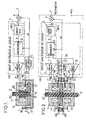
- variable-reluctance linear motor subject of the present invention comprises at least one electromagnet exerting, in operation, a force of attraction, this electromagnet comprising, as shown in the above-mentioned figure, a carcass 1 forming a magnetic circuit 9, and a toroidal winding 11 around a direction ⁇ of linear displacement.
- a mobile magnetic part 17 is provided, this magnetic part being generally of the same section as that of the electromagnet.
- the latter may include a guide element 2, formed for example by an index 20 for guiding displacement along the displacement path materialized by the direction ⁇ of linear displacement relative to the carcass 1, this displacement being of course generated under the effect of the attractive force exerted by the electromagnet.
- the guide element 2 can be formed by any means equivalent to the index 20.
- the index 20 can be mounted on a suspension with two deformable bearings made of elastomer or metal.
- one of the stages can be constituted by the aforementioned corner bearings, the other stage, constituted by a loudspeaker membrane, for example, being able to be placed on the load. .
- a circuit 3 for detecting the movement of the mobile magnetic part 17 is provided and delivers a signal, denoted sd , representative of the movement of the mobile magnetic part relative to the frame 1 of the electromagnet.
- This detector circuit 3 is formed by a sensor for inductive or capacitive measurement of the instantaneous value of the air gap 18, this value being noted ef in FIG. 1, existing between the carcass 1 and the mobile magnetic part 17 previously mentioned.
- a subtractor element 4 is provided and receives on a first positive input a signal e for controlling the movement of the movable magnetic part 17 and on a second negative input the signal representative of the displacement, sd .
- the subtractor element 4 delivers an error signal ⁇ of displacement of the mobile part 17 relative to the displacement control signal.
- a current amplifier circuit, CAC receives the error signal ⁇ and delivers a supply current to the winding 11 of the electromagnet by wires F1, F2.
- a return element, 28, is provided in order to ensure the return of the mobile magnetic part 17 by exerting on it a return force of opposite direction to that of the force exerted by the electromagnet.
- variable reluctance variable linear motor object of the present invention as shown in FIG. 1 is as follows: when the coil 11 of the electromagnet is supplied with a current, an attractive force of the electromagnet thus supplied is exerted on the mobile magnetic part 17 in causing a displacement by attraction of the latter towards the carcass 1.
- the return element 28, as shown in FIG. 1 in a nonlimiting manner by a mechanical element, makes it possible to maintain in dynamic equilibrium the crew formed by the part 17 moving magnetic and the guide index 20 along the direction of travel ⁇ .
- the movement itself is controlled and the force exerted by the electromagnet is controlled as a function of the movement of the movable magnetic part 17.
- the displacement detector circuit 3 makes it possible to measure this displacement of the mobile magnetic part 17, that is to say of the instantaneous value of the air gap ef, according to a constant of proportionality to the value of the signal e movement control; this constant only depends on the parameters of the servo circuit, which will be described in more detail below in the description.
- the return element 28 can be constituted by a mechanical element such as a return spring of the helical spring type for example.
- the latter is then engaged on the index 20 for guiding the displacement of the movable magnetic part 17, as shown in FIG. 1 above.
- the assembly formed by the guide index 20 and the spring 28 is then slidably mounted in a housing 16 of the carcass 1.
- the return element 12 is constituted by an electromagnet counter similar to the electromagnet.
- the electromagnet is constituted by the carcass 1 forming a magnetic circuit 9, the coil 11 and the direction of movement ⁇ materialized by the guide index 20, while the electromagnet against is formed by a second carcass 1 ', symmetrical with the first carcass 1, a second similar winding 12, the electromagnet against the electromagnet and being arranged opposite, on either side of the movable magnetic part 17 , as shown in Figure 2.
- the index 20 for guiding the movable magnetic part 17 extends symmetrically with respect to the movable magnetic part 17 and the guidance of the movable magnetic part 17 during operation is simultaneously provided by the carcass 1 of the electromagnet and by the carcass 1 'of the electromagnet.
- a symmetrical control circuit, denoted MCS, of the electromagnet, respectively of the electromagnet, makes it possible to deliver to the respective windings 11, 12, of the latter a supply current in symmetrical excitation, as well as 'It will be explained below in the description.
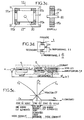
- FIG. 3a there is shown a top view of the mechanical part of the servo-linear motor object of the present invention.
- the motor comprises the carcass 1 or frame, formed in fact of the electromagnet and against the electromagnet as previously mentioned.
- the carcass 1 as well as the carcass 1 ′ of the electromagnet against can advantageously be formed by a magnetic circuit 9, 10, as shown in FIG. 3b, which is a sectional view along the plane of symmetry AA of Figure 3a.
- Each magnetic circuit can advantageously be formed by a magnetic circuit made of laminated or sintered ferromagnetic material to limit magnetic losses.
- an electrical winding 11, respectively 12 is provided, to form the electromagnet, respectively the electromagnet against.
- Each winding is then supplied by two supply wires, F1, F2, respectively F3, F4.
- the electromagnet, respectively the electromagnet are kept at a fixed distance from each other by mechanical connecting parts, denoted 13, respectively 14, the part 15 as shown in FIGS. 3a and 3b used for fixing the carcass, for example.
- the moving element is formed of a rod forming a guide index 20 and made of a plastic material, such as a plastic material of the self-lubricating type.
- the rod 20 is inserted in the mobile magnetic part 17, itself formed by a plate made of sintered or laminated ferro-magnetic material in order to limit the corresponding magnetic losses.
- the equipment constituted by the rod 20 forming a guide index and by the movable magnetic part 17 is guided in translation by the guide index 20, which passes through the carcass 1, 1 ′ of the electromagnet, respectively of the electro-counter -magnet.
- the passages provided in the aforementioned carcass are preferably adjusted so as to minimize the friction between the rod proper 20, and the wall of the orifices allowing the passage of the latter.
- the mobile magnetic part 17 is thus kept parallel to the electromagnet, respectively to the electromagnet, via the above-mentioned adjusted passages, during its displacements during the operation of the linear motor with variable reluctance object of the present invention.
- the operating mode of the linear reluctant variable reluctance motor object of the present invention as shown in Figure 2 and 3a, 3b is as follows.
- the displacement thereof is ensured in one direction or the other. So that this movement is controlled, the force applied by the electromagnet, respectively the electromagnet, is controlled as a function of the movement of the movable magnetic part 17.
- the abovementioned servo-control is produced by means of a circuit detecting the displacement of the mobile magnetic part 17, which will be described in connection with FIGS. 4 and 5a, 5b below.
- the symmetrical control circuit MCS advantageously comprises a circuit 30 for detecting the differential displacement of the movable magnetic part 17, this detector circuit 30 delivering to the negative terminal of the subtractor 4 a signal sd representative of the differential displacement of the part magnetic mobile with respect to the carcass 1, 1 ′, of the electromagnet and of the electromagnet against a position of origin of equilibrium.
- a supply current amplifier circuit in symmetrical excitation
- power supply denoted CAC
- CAC in symmetrical excitation
- this circuit comprising, on the one hand, a module denoted symmetrical control MOCS receiving the error signal ⁇ delivered by the subtractor circuit 4, and delivering a first and a second symmetrical excitation control signal, noted sa, sb.
- the symmetrical excitation supply current amplifier circuit, CAC comprises, on the other hand, two current amplifiers 7, 8 receiving the first respectively the second symmetrical excitation control signal, and delivering to the winding of the electro -magnet 11, respectively of the electromagnet against 12, a corresponding symmetrical excitation supply current.
- the principle of measuring the displacement of the mobile magnetic part 17 consists in measuring a quantity which varies with the air gaps 18 and 19 previously mentioned, and in particular the values efa, efb, of the latter. , or better with their difference.
- the above-mentioned measurement can be carried out inductively or capacitively.
- the inductive method consists in measuring the inductance of the two windings 11 and 12, according to the corresponding air gap values.
- the value of the aforementioned inductors can then be easily calculated by measuring, on the one hand, the voltage at the terminals of each winding, and the derivative of the supply current of the latter, the value of the derivative of this current can be measured from an auxiliary winding of low known value, the instantaneous voltage at the terminals of this auxiliary winding representing the value of the derivative of the supply current of the winding considered.
- a measurement of the voltage U11, respectively U12, applied to the winding 11, respectively 12, of the electromagnet and of the electromagnet and the measurement of the voltages at the terminals of the auxiliary windings 31 and 32, u11, u12, then allows to determine the corresponding values of L inductance of the electromagnet, respectively of the electromagnet, and ultimately, the corresponding air gap values efa, efb.
- the above-mentioned voltage values can be measured by sampling, analog-digital conversion, the calculation then being able to then be performed digitally for example.
- a more advantageous solution may consist in using an isolation transformer, supplied with the primary by the current I, which moreover makes it possible to adapt the level of the measured signal.
- the voltage delivered by the secondary of the isolation transformer is thus proportional to dI dt and to ef.
- the isolation transformer it is possible to measure the current I flowing in the electromagnets. Knowledge of the value of this current is necessary when the amplifiers 7 and 8 are current controlled.
- a Hall effect sensor CM is placed in the magnetic circuit of the isolation transformer, which delivers a voltage U proportional to I. This type of sensor is easy to implement.
- the sensor circuit 3 can advantageously be produced in the form of the differential displacement detector circuit 30, as shown in FIGS. 2 and 4.
- the electromagnet and the counter-magnet, the movable magnetic part 17, and the 2 air gaps 18 and 19 then constitute a double capacitor, which, as shown in FIG. 4, is connected by connection wires F5, F6 and F7, to a measurement bridge comprising equal resistors 20 and 21.
- These resistors can be constituted by resistors of precision.
- the measuring bridge circuit advantageously comprises two first adjacent branches formed by the capacities of the above-mentioned air gaps 18, 19, constituted by the frame 1 of the electromagnet and the first face of the magnetic part 17 movable vis-à-vis, respectively by the carcass 1 'of the electromagnet, and the second face of the magnetic part 17 mobile vis-à-vis.
- the bridge measurement circuit comprises two adjacent second branches formed by the resistors, 20 and 21.
- a first diagonal of the bridge measurement circuit is formed by a generator 220 of periodic signals whose fundamental frequency is much higher than the cut-off frequency of the controlled linear motor.
- the fundamental frequency of the signal delivered by the generator 220 can be chosen equal to 50 kHz.
- the second diagonal of the measurement bridge delivers a differential measurement signal, denoted vm , between the movable magnetic part 17 and the common point of the two adjacent second branches formed by the standard resistors 20 and 21.
- a demodulator circuit 22 receives, on the one hand, the differential measurement signal, vm, and on the other hand, the periodic excitation signals, delivered by the generator 220, in order to ensure demodulation of the differential measurement signal, the demodulator circuit thus conventionally delivering the envelope signal of amplitude of the differential measurement signal vm. This signal is noted se in FIG. 4.
- a filtering circuit 23 of the low-pass filter type is provided, this circuit receiving the envelope signal se, and delivering the signal sd representative of the differential displacement of the mobile magnetic part 17.
- This filter removes high frequency demodulation products.
- the detector device used as described in connection with Figures 3b and 4 is no longer a separate element, expensive and bulky, which it is necessary to add.
- the rod 20 constituting the guide index must be made of an insulating material, in self-lubricating plastic material for example, as well as the previously mentioned connecting pieces.
- the insulating parts can also be made of ceramic, which makes it possible to obtain greater rigidity.
- the parts of the carcasses 1 and 1 ′ facing the first, respectively second face of the mobile magnetic part 17 can advantageously be provided, as shown in FIG. 3b, of an electrically conductive coating 110, 120.
- the electrically conductive coating can advantageously be formed by a metallized plastic film, the metallization of which is electrically connected or not to the potential of each corresponding carcass 1 or 1 '.
- Such a coating 110, 120 makes it possible to improve the assimilation of the characteristics of each capacitor formed by the air gaps efa, efb, to those of a flat capacitor, and therefore the accuracy of the measurement.
- the electrodes formed by the coating 110, 120 are disturbed by capacitive coupling to the coils 11 and 12, the potential of which is variable.
- the noise level of the sensor thus formed can be eliminated or greatly reduced by covering each coil with a shielding plate connected to the reference potential.
- the armor plate, covering the coil, has a cut so that this plate cannot constitute a turn completely surrounding an area subjected to a variable magnetic flux.
- these could advantageously be configured according to a divided structure, in the absence of a loop, such as a comb structure.
- the shielding plate and the divided electrode can then be produced according to the techniques of flexible printed circuits, double-sided, the face comprising the shielding plate being applied to the corresponding coil.
- the demodulation carried out by the demodulator 22 makes it possible to obtain a continuous output voltage thanks to the demodulation carried out by the frequency of the excitation signal delivered by the generator 220, then to low-pass type filtering by the filter 23.
- the signal sd delivered at the output of the low-pass filter 23 and at the output of the detector circuit 3 or 30 is then proportional to the displacement d of the mobile magnetic part 17.
- the subtractor circuit 4 then makes the difference between the signal sd, representative of the displacement of the movable magnetic part 17, and the control signal e of displacement, which of course represents the displacement instruction for the crew constituted by the mobile magnetic part 17 and by the index 20.
- the output signal ⁇ or error signal delivered by the subtractor 4 represents the error between the actual position and the position requested for the above-mentioned crew.
- the subtractor circuit 4 can advantageously be produced by means of an operational amplifier mounted as a differential amplifier.
- the MOCS module for linear symmetrical control advantageously comprises a servo correction circuit 5, ensuring the stability of the servo depending on the mechanical impedance or load to which the motor, object of the present invention, is connected.
- This circuit receives the error signal ⁇ delivered by the subtractor circuit 4 and delivers a corrected error signal ⁇ .
- the servo-control corrector circuit 5 will not be described since it corresponds to a conventional type circuit in the field of servo motors, this type of circuit being intended above all to improve the performance of the servo-control in terms of response time and depreciation.
- the linear symmetric control MOCS module further comprises a linearizer circuit 6 making it possible to control the windings 11, 12, of the electromagnet, respectively of the electromagnet, in slaving of the current or the magnetic flux. traversing these electromagnets, so as to make the displacement of the movable magnetic part 17 and of the index 2 linear in the direction of displacement ⁇ with respect to the input control signal e.
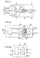
- a first embodiment of the linearizer circuit 6 will be described in connection with FIG. 5a.
- the linearizer circuit 6 advantageously comprises a rectifier-separator circuit 24 delivering, from the corrected error signal ⁇ , delivered by the servo-correction circuit 5, the positive and negative alternations, rectified by the signal d 'error corrected ⁇ .
- the circuit 24 in fact delivers the positive, respectively negative, rectified values, of the corrected error signal ⁇ , the latter being presumed to correspond to an input signal AC e for which the error signal ⁇ and the corrected error signal ⁇ are themselves formed by a signal with positive and negative alternation.
- the circuit 24 separator rectifier could be constituted by two circuits of alignment of the alternations of conventional type, a first circuit making it possible to align the positive alternations from the value 0, and a second circuit, similar to the first, allowing the negative half-waves to be aligned on the value 0.
- This type of conventional circuit will not be described since it is perfectly known to those skilled in the art.
- the linearizer circuit 6 can advantageously include a first, 25a, and a second, 25b, circuit for calculating the square root of the amplitude of the positive and negative alternations, rectified by the signal d 'error corrected ⁇ .
- the aforementioned circuits 25a and 25b can be produced by analog circuits and deliver proportional signals, respectively to ⁇ ⁇ at and ⁇ ⁇ b .
- the linearizer circuit 6 comprises a first, 27a, and a second, 27b, correction multiplier circuit receiving the signals respectively.
- ⁇ ⁇ at , respectively ⁇ ⁇ b , delivered by the calculation circuits 25a, 25b.
- a subtractor circuit 26a and a summing circuit 26b receive, on the one hand, the differential detection signal sd, proportional to d, displacement of the movable magnetic part 17, and, on the other hand, a signal representative of the value eo of the air gaps when the movable magnetic part 17 is in the middle position and deliver signals representative of the values eo-d, eo + d at the first, 27a, respectively second, 27b, correction circuit.
- circuits 27a and 27b deliver a first, sa, respectively a second, sb, symmetrical control signal to the first, 7, respectively second, 8, current amplifier.
- the linearizer circuit 6, as shown in FIG. 5a, makes it possible to ensure linearization of the nonlinear characteristic of the electromagnets, with regard to the expression of the force that the latter produce as a function of the intensity traversing the corresponding windings.
- the aforementioned force therefore varies as the square of the current and as the inverse of the square of the value of the air gap.
- the control signal ⁇ of the linearizer 6 represents the force setpoint. This is, in the first place, separated in its positive part and in its negative part by the circuit 24 described above due to the fact that an electromagnet can only produce attractive forces. According to the sign of the force to be produced, it is necessary to supply one or the other of the windings of the electromagnet, respectively of the electromagnet against.
- Circuit 25a or 25b calculates the square root of the signal, and circuit 27a or 27b multiplies the result by a voltage representative of the instantaneous value of the air gap, i.e. proportional to e0 + d or to e0-d, depending on the value efa, efb of the air gap 18 or 19 considered.
- the servo-control can be made more efficient by the servo-control of the magnetic flux in the electromagnet and the electromagnet against the value of the displacement command reference signal e and no longer by servo-controlling the current.
- the carcass 1 of the electromagnet and the carcass 1 'of the electromagnet against advantageously comprise at the air gap 18, 19 a Hall effect measurement probe 27,29, as shown for example in Figure 3b.
- the Hall effect measurement probe 27,29 delivers, via connection wires F8, F9, a signal representative of the magnetic flux generated in the air gap 18, 19 corresponding to the current amplifier 7, respectively 8 , as shown in FIG. 2.
- the magnetic flux in the air gap is proportional to the setpoint input of the current amplifiers 7 and 8.
- the linearizer circuit is simplified and comprises, a rectifier-separator circuit 24 delivering, from the corrected error signal ⁇ delivered by the servo-correction circuit 5, the positive half-waves, respectively negative, corrected by the corrected error signal ⁇ as described above in connection with FIG. 5a followed by a first, 25a, and a second, 25b, circuit for calculating the square root of the amplitude of the half-waves positive, respectively negative, adjusted by the corrected error signal ⁇ .
- Each calculation circuit 25a, 25b delivers a proportional signal, respectively to ⁇ ⁇ at , ⁇ ⁇ b , respectively constituting the differential control signals, sa, sb.
- the linearizer 6 contains only the first two stages of the linearizer shown in Figure 5a.
- the correction of the non-linearity due to the dependence of the force, exerted by the electromagnet respectively against the electromagnet, due to the square of the current flowing through their respective coil or of the magnetic flux thus created is obtained by the introduction into the feedback loop of the servo-control, that is to say at the level of the connection wires F8, F9, of Hall effect probes to amplifiers 7, respectively 8, of an operating circuit of square function, delivering to the winding 11, 12, of the electromagnet respectively of the electromagnet against a signal proportional to the square of the magnetic flux generated in each corresponding air gap 18, 19 (the linearizer circuit 6 of FIG. 5b then comprises the only rectifier-separator circuit 24 described above in connection with FIG. 5a).
- the linearizer circuit 6 of FIG. 5b then comprises the only rectifier-separator circuit 24 described above in connection with FIG. 5a).
- the practical implementation of the servo correction circuit 5 and the linearizer circuit 6 can be either analog or digital.
- these circuits can advantageously be produced by means of a fast signal processor such as the processor sold under the reference TMS 320 C 25 by the company TEXAS INSTRUMENTS.
- the servo correction circuit 5 is produced by means of operational amplifiers and the linearizer circuit 6 can be produced from analog multipliers such as the circuit sold under the reference AD 534 by the company ANALOG DEVICES, these circuits making it possible to carry out the operations of square root and multiplication.
- Hall effect sensors As regards the installation of Hall effect sensors, these can be carried out using sensors sold by the company SPRAGUE under the reference UGN 3503 U.
- the aforementioned Hall effect sensors can be placed either in the air gap, or, more advantageously, in the magnetic circuit or in a derivation of the latter, so as to deliver a signal representative of the flux generated in the air gap.
- a description of an alternative embodiment of the linearizer described above in conjunction with FIGS. 2 and 5b will now be given in conjunction with FIG. 5c, in the context of a digital control, in principle more precise than an analog control.
- the linearizer described previously in the description feeds only one coil 11 or 12 at a time. It is therefore likely to generate a distortion at the moment through the zero value of the applied force.
- the coils used have, in principle, a high impedance to the current transients, so that the current, in the coil subjected to excitation, does not have time to be established when the current in the coil switched to stop becomes zero . This results in a corresponding disturbance of the force produced.
- the numerical control makes it possible to use laws or processes of linearization much finer than the simple calculation of the square root previously described.
- the linearization process can consist in supplying each coil 11, 12, with a current of the same intensity I o when the requested force is zero.
- the forces produced by each coil 11, 12, on the moving part 17 compensate each other.
- the linearizer 6 is controlled in differential mode, the current in one of the coils is increased to a value I o + i, that in the other coil is decreased to the symmetrical value I o -i.
- the current in the corresponding coil becomes zero and that in the other coil reaches then exceeds 2 I o , and can then be determined according to the law of the square root, since we return to the case previously described in the description where only one of the coils 11, 12 is supplied.
- the air gap compensations are carried out in the same way as described above.
- circuits correctors 5, and linearizer 6, with if necessary the air gap correction 60 can be produced by a digital processor programmed so as to deliver the magnetic flux setpoints Fa and Fb as shown in FIG. 5c, for a force setpoint F given following the processing of the correction module, under the differential or exclusive supply conditions of the two respectively of a single coil 11, 12.
- FIGS. 6a and 6b An alternative embodiment of a linear motor according to the object of the present invention will be described in connection with FIGS. 6a and 6b in the case where the mobile magnetic part 17 is liable to be subjected to a rotational movement, around a center of rotation C.
- the same reference numerals designate the same elements as in the previous figures.
- the winding 11 is placed around the path of linear displacement ⁇ , which corresponds to a displacement in rotation on an arc of a circle with an opening angle ⁇ f.
- the mobile magnetic part 17 is mobile in rotation, in the direction of movement ⁇ , and mechanically guided so as to have a single degree of freedom relative to the carcass 1 of the electromagnet.
- the direction of movement ⁇ is then substantially tangent to that of the lines of the magnetic field created by the electromagnet 11 in the air gap.
- the movable magnetic part 17 is subjected to a rotational movement relative to a center of rotation C and is rotatably mounted relative to an axis of rotation 21 mechanically integral with the carcass 1 and orthogonal to the movement path ⁇ .
- FIG. 6b an alternative embodiment is shown comprising, analogously to FIG. 2, a magnet 11 and a counter magnet 12.
- a deflection angle ⁇ f M or ⁇ a M , ⁇ b M , of the mobile magnetic part less than or equal to 10 degrees.
- variable reluctance linear motor object of the present invention as shown in Figures 6a or 6b, in its rotational displacement version can be used in all cases where one has to precisely control the oscillating rotational movements of low amplitude at high frequency, for example for active control of pressure pulsations in flows using an oscillating butterfly mounted for rotation in a tube.
- the linear motor with variable reluctance object of the present invention is, secondly, particularly advantageous insofar as a linearity of movement of the moving assembly, depending only on the performance of the electronic components of the chain control, can be obtained, the linearity defect of the whole system can then be made equal to a value of the order of 0.1%.
- the linearity characteristic of the response of the linear servo motor object of the present invention associated with the value of the bandwidth or the cut-off frequency thereof makes it possible to envisage the corresponding applications in terms of reproduction.
- the linear motor with variable reluctance object of the present invention then playing the role of a transducer comparable, and in any case superior, to the electrodynamic motor of conventional type, the constraint relating to the mechanical impedance of the associated membrane in such an application to the mobile crew, and in particular to the guide index 20 of the linear motor object of the present invention to constitute for example a loudspeaker, which can be made as low as possible, or in any case completely compensated by the servo-correction circuit 5 and by the linearizer circuit to ensure faithful reproduction of the control signal and its translation in the form of corresponding sound vibrations.
Landscapes
- Engineering & Computer Science (AREA)
- Physics & Mathematics (AREA)
- General Engineering & Computer Science (AREA)
- Electromagnetism (AREA)
- Power Engineering (AREA)
- Mechanical Engineering (AREA)
- Aviation & Aerospace Engineering (AREA)
- Acoustics & Sound (AREA)
- General Physics & Mathematics (AREA)
- Control Of Linear Motors (AREA)
- Reciprocating, Oscillating Or Vibrating Motors (AREA)
- Electrostatic, Electromagnetic, Magneto- Strictive, And Variable-Resistance Transducers (AREA)
- Control Of Position Or Direction (AREA)
Applications Claiming Priority (2)
| Application Number | Priority Date | Filing Date | Title |
|---|---|---|---|
| FR9114576A FR2684251B1 (fr) | 1991-11-26 | 1991-11-26 | Moteur lineaire asservi a reluctance variable. |
| FR9114576 | 1991-11-26 |
Publications (2)
| Publication Number | Publication Date |
|---|---|
| EP0544576A1 true EP0544576A1 (de) | 1993-06-02 |
| EP0544576B1 EP0544576B1 (de) | 1998-10-28 |
Family
ID=9419337
Family Applications (1)
| Application Number | Title | Priority Date | Filing Date |
|---|---|---|---|
| EP92403147A Expired - Lifetime EP0544576B1 (de) | 1991-11-26 | 1992-11-23 | Linear Servomotor mit veränderlicher Reluktanz |
Country Status (6)
| Country | Link |
|---|---|
| US (1) | US5621293A (de) |
| EP (1) | EP0544576B1 (de) |
| JP (1) | JP2749748B2 (de) |
| DE (1) | DE69227435T2 (de) |
| ES (1) | ES2122988T3 (de) |
| FR (1) | FR2684251B1 (de) |
Cited By (9)
| Publication number | Priority date | Publication date | Assignee | Title |
|---|---|---|---|---|
| FR2711408A1 (fr) * | 1993-10-19 | 1995-04-28 | Hutchinson | Perfectionnements aux dispositifs antivibratoires hydrauliques. |
| WO1995023301A1 (de) * | 1994-02-28 | 1995-08-31 | Clouth Gummiwerke Ag | Verfahren zur aktiven schwingungsdämpfung und ein system zu dessen durchführung |
| FR2753873A1 (fr) * | 1996-09-24 | 1998-03-27 | Thomson Marconi Sonar Sas | Procede d'asservissement d'un transducteur a reluctance variable, et moteur lineaire pour la mise en oeuvre d'un tel procede |
| EP0893620A1 (de) * | 1997-07-23 | 1999-01-27 | Hutchinson | Elektromagnetischer Betätiger und hydraulisches Antischwingungslager mit einem solchen Betätiger |
| US5939793A (en) * | 1994-02-28 | 1999-08-17 | Isad Electronic Systems Gmbh & Co. Kg | Starter for drive units, especially internal combustion engines, and process for operating the same |
| FR2775538A1 (fr) * | 1998-03-02 | 1999-09-03 | Valeo Systemes De Fermetures | Actionneur electro-mecanique auto-asservi en position et vehicule automobile equipe de cet actionneur |
| US6236296B1 (en) | 1999-05-17 | 2001-05-22 | Hutchinson | Electromagnetic actuator |
| WO2007134287A1 (en) * | 2006-05-12 | 2007-11-22 | Parker-Hannifin Corporation | Displacement measurement device |
| CN101850523A (zh) * | 2010-03-18 | 2010-10-06 | 沈阳工业大学 | 数控机床直线同步电动机磁悬浮进给平台 |
Families Citing this family (25)
| Publication number | Priority date | Publication date | Assignee | Title |
|---|---|---|---|---|
| FR2705395B1 (fr) * | 1993-05-13 | 1995-07-28 | Hutchinson | Double vitrage antivibratoire. |
| US5754017A (en) * | 1995-12-26 | 1998-05-19 | Asmo Co., Ltd. | Power window with detecting function of sticking of foreign matter |
| DE19716540A1 (de) * | 1997-04-19 | 1998-10-22 | Bosch Gmbh Robert | Elektromagnet zur Betätigung des Stellglieds eines Ventils |
| FR2765647B1 (fr) * | 1997-07-07 | 2002-01-11 | Jacques Clausin | Reducteur de vibrations monoaxe accorde a bande large et de grande legerete |
| WO1999021198A1 (fr) * | 1997-10-17 | 1999-04-29 | Jacques Clausin | Dispositif de commande proportionnelle de force delivree par un electro-aimant independante des variations des tensions d'alimentation et des entrefers |
| GB2354054B (en) * | 1999-09-03 | 2001-08-08 | Avon Vibration Man Syst Ltd | Controlling vibrations |
| JP2001221653A (ja) | 1999-12-01 | 2001-08-17 | Honda Motor Co Ltd | 変位検出装置 |
| US6388417B1 (en) | 1999-12-06 | 2002-05-14 | Macrosonix Corporation | High stability dynamic force motor |
| WO2003001547A1 (en) * | 2001-06-21 | 2003-01-03 | Honeywell International Inc. | Solenoid actuator with position-independent force |
| US6701876B2 (en) * | 2001-09-27 | 2004-03-09 | Visteon Global Technologies, Inc. | Electromechanical engine valve actuator system with reduced armature impact |
| US6895809B2 (en) * | 2002-12-31 | 2005-05-24 | Spx Corporation | Method and apparatus for testing a motor |
| US7501834B2 (en) * | 2005-06-21 | 2009-03-10 | Custom Sensors & Technologies, Inc. | Voice coil actuator with embedded capacitive sensor for motion, position and/or acceleration detection |
| US7345372B2 (en) * | 2006-03-08 | 2008-03-18 | Perpetuum Ltd. | Electromechanical generator for, and method of, converting mechanical vibrational energy into electrical energy |
| CN100593767C (zh) * | 2006-06-30 | 2010-03-10 | 深圳市大族激光科技股份有限公司 | 电容传感器的控制方法 |
| KR101013588B1 (ko) | 2008-10-14 | 2011-02-14 | 한국철도기술연구원 | 선형동기전동기의 위치검출장치 |
| DE102010061955B4 (de) * | 2010-11-25 | 2014-03-13 | Rolls-Royce Deutschland Ltd & Co Kg | Induktiver Sensor |
| AT513617B1 (de) * | 2012-12-21 | 2014-06-15 | Seh Ltd | Magnetvorrichtung umfassend eine auf den Translator wirkende Beschleunigungseinheit |
| EP3005540A1 (de) * | 2013-08-26 | 2016-04-13 | Halliburton Energy Services, Inc. | Wandler mit variabler reluktanz |
| CN111035364A (zh) | 2014-09-24 | 2020-04-21 | 泰克宣技术有限公司 | 用于向用户的皮肤施加运动的设备 |
| US10573139B2 (en) | 2015-09-16 | 2020-02-25 | Taction Technology, Inc. | Tactile transducer with digital signal processing for improved fidelity |
| CN108111088B (zh) * | 2017-12-23 | 2020-08-18 | 西安交通大学 | 一种考虑气隙波动的永磁同步直线电机推力精确预测方法 |
| JP6715272B2 (ja) * | 2018-02-20 | 2020-07-01 | Ckd株式会社 | ソレノイドのプランジャの位置検出装置 |
| JP2020073279A (ja) * | 2020-02-18 | 2020-05-14 | ミネベアミツミ株式会社 | 振動発生装置及び電子機器 |
| FR3118257A1 (fr) * | 2020-12-18 | 2022-06-24 | Sagemcom Broadband Sas | Procédé et dispositif de transmission de signaux optiques à puissance moyenne adaptée à la température et au vieillissement, programme informatique et support de programme correspondants. |
| CN117938018B (zh) * | 2024-03-20 | 2024-07-12 | 深圳大学 | 一种调姿平台的电机姿态控制方法、装置及设备 |
Citations (2)
| Publication number | Priority date | Publication date | Assignee | Title |
|---|---|---|---|---|
| EP0379391A1 (de) * | 1989-01-17 | 1990-07-25 | Tektronix, Inc. | Geschwindigkeitssteuerung für Massen |
| EP0440536A1 (de) * | 1990-01-30 | 1991-08-07 | Hutchinson | Verbesserungen zu hydraulischen schwingungsverhindernden Vorrichtungen |
Family Cites Families (25)
| Publication number | Priority date | Publication date | Assignee | Title |
|---|---|---|---|---|
| US4041529A (en) * | 1976-04-12 | 1977-08-09 | The Raymond Lee Organization, Inc. | Airplane route viewing system |
| JPS5355597A (en) * | 1976-10-28 | 1978-05-20 | Inoue Japax Res Inc | Device for horizontally moving working table or spindle |
| JPS54149030A (en) * | 1978-05-15 | 1979-11-21 | Babcock Hitachi Kk | Two-layer type low-pollution combustion device |
| LU80496A1 (fr) * | 1978-11-09 | 1980-06-05 | Cockerill | Procede et diopositif pour le depot electrolytique en continu et a haute densite de courant d'un metal de recouvrement sur une tole |
| US4331263A (en) * | 1979-11-30 | 1982-05-25 | Christopher Scientific Co., Inc. | Control unit for use in a vibratory feeder system |
| US4352048A (en) * | 1980-02-19 | 1982-09-28 | Ontrax Corporation | Electromagnetic actuator apparatus |
| US4431985A (en) * | 1981-03-02 | 1984-02-14 | Honeywell Inc. | Stepper motor system for digitally measuring input quantities |
| US4370604A (en) * | 1981-06-25 | 1983-01-25 | Honeywell Inc. | Solenoid actuated servo system |
| JPS59132765A (ja) * | 1983-01-20 | 1984-07-30 | Nippon Telegr & Teleph Corp <Ntt> | 傾斜駆動制御装置 |
| JPS608540A (ja) * | 1983-06-27 | 1985-01-17 | Nissan Motor Co Ltd | 防振装置 |
| JPS6187151A (ja) * | 1984-09-11 | 1986-05-02 | Toray Ind Inc | 画像形成膜の製造方法 |
| IE55855B1 (en) * | 1984-10-19 | 1991-01-30 | Kollmorgen Ireland Ltd | Position and speed sensors |
| US4616153A (en) * | 1984-12-10 | 1986-10-07 | Lee Robert E | Closed-loop linear position servomotor |
| JPS61214011A (ja) * | 1985-03-20 | 1986-09-22 | Res Dev Corp Of Japan | 可動鉄片型電磁石アクチユエ−タ |
| JPH0619668B2 (ja) * | 1985-03-22 | 1994-03-16 | 新技術事業団 | 可動鉄心型電磁石アクチユエ−タ |
| DE3515350A1 (de) * | 1985-04-27 | 1987-01-22 | Messerschmitt Boelkow Blohm | Magnetregler fuer langstator-magnetschwebefahrzeuge |
| SU1280318A1 (ru) * | 1985-06-05 | 1986-12-30 | Специальное Конструкторско-Технологическое Бюро С Опытным Производством Минского Радиотехнического Института | Оптико-электронное устройство дл измерени линейных перемещений |
| JPS62123578A (ja) * | 1985-11-22 | 1987-06-04 | Toshiba Corp | 郵便番号自動読取区分装置 |
| DE3628535A1 (de) * | 1986-08-22 | 1988-03-03 | Vdo Schindling | Anordnung zur betaetigung eines stellgliedes |
| JPS63136113A (ja) * | 1986-11-26 | 1988-06-08 | Koyo Seiko Co Ltd | 磁気浮上スライド装置 |
| US4717865A (en) * | 1987-05-29 | 1988-01-05 | Westinghouse Electric Corp. | Transportation apparatus |
| GB8814777D0 (en) * | 1988-06-22 | 1988-07-27 | Renishaw Plc | Controlled linear motor |
| JPH07108101B2 (ja) * | 1989-02-28 | 1995-11-15 | オ−クマ株式会社 | リニアアクチュエータ駆動制御装置 |
| DE3918753C1 (de) * | 1989-06-08 | 1990-07-12 | Fa. Carl Freudenberg, 6940 Weinheim, De | |
| US5257681A (en) * | 1992-09-28 | 1993-11-02 | Trw Inc. | Apparatus for damping movement |
-
1991
- 1991-11-26 FR FR9114576A patent/FR2684251B1/fr not_active Expired - Fee Related
-
1992
- 1992-11-23 EP EP92403147A patent/EP0544576B1/de not_active Expired - Lifetime
- 1992-11-23 ES ES92403147T patent/ES2122988T3/es not_active Expired - Lifetime
- 1992-11-23 DE DE69227435T patent/DE69227435T2/de not_active Expired - Fee Related
- 1992-11-25 US US07/981,484 patent/US5621293A/en not_active Expired - Fee Related
- 1992-11-26 JP JP4317495A patent/JP2749748B2/ja not_active Expired - Lifetime
Patent Citations (2)
| Publication number | Priority date | Publication date | Assignee | Title |
|---|---|---|---|---|
| EP0379391A1 (de) * | 1989-01-17 | 1990-07-25 | Tektronix, Inc. | Geschwindigkeitssteuerung für Massen |
| EP0440536A1 (de) * | 1990-01-30 | 1991-08-07 | Hutchinson | Verbesserungen zu hydraulischen schwingungsverhindernden Vorrichtungen |
Non-Patent Citations (3)
| Title |
|---|
| IEEE JOURNAL OF SOLID-STATE CIRCUITS vol. 25, no. 2, Avril 1990, NEW YORK pages 441 - 450 FATHY F. YASSA ET AL. 'A Multichannel Digital Demodulator for LVDT/RVDT Position Sensors' * |
| JAPANESE PATENTS REPORT Section EI, Week 8733, 26 Août 1987 Derwent Publications Ltd., London, GB; Class S, AN 87-233564 & SU-A-1 280 318 (MINSK WIRELESS ENG) 30 Décembre 1986 * |
| TECHNISCHES MESSEN TM. vol. 49, no. 2, Février 1982, MUNCHEN DE pages 43 - 49 P. KRISCHKER ET AL. 'Induktiver Differential-Querankergeber hoher Auflösung' * |
Cited By (15)
| Publication number | Priority date | Publication date | Assignee | Title |
|---|---|---|---|---|
| FR2711408A1 (fr) * | 1993-10-19 | 1995-04-28 | Hutchinson | Perfectionnements aux dispositifs antivibratoires hydrauliques. |
| US5921149A (en) * | 1994-02-28 | 1999-07-13 | Isad Electronic Systems Gmbh & Co. Kg | System and process for active vibration damping |
| WO1995023301A1 (de) * | 1994-02-28 | 1995-08-31 | Clouth Gummiwerke Ag | Verfahren zur aktiven schwingungsdämpfung und ein system zu dessen durchführung |
| US5939793A (en) * | 1994-02-28 | 1999-08-17 | Isad Electronic Systems Gmbh & Co. Kg | Starter for drive units, especially internal combustion engines, and process for operating the same |
| WO1998014033A1 (fr) * | 1996-09-24 | 1998-04-02 | Thomson Marconi Sonar S.A.S. | Procede d'asservissement d'un transducteur a reluctance variable, et moteur lineaire pour la mise en oeuvre d'un tel procede |
| FR2753873A1 (fr) * | 1996-09-24 | 1998-03-27 | Thomson Marconi Sonar Sas | Procede d'asservissement d'un transducteur a reluctance variable, et moteur lineaire pour la mise en oeuvre d'un tel procede |
| FR2766607A1 (fr) * | 1997-07-23 | 1999-01-29 | Hutchinson | Actionneur electromagnetique, et support antivibratoire hydraulique comportant un tel actionneur |
| EP0893620A1 (de) * | 1997-07-23 | 1999-01-27 | Hutchinson | Elektromagnetischer Betätiger und hydraulisches Antischwingungslager mit einem solchen Betätiger |
| US5961104A (en) * | 1997-07-23 | 1999-10-05 | Hutchinson | Electromagnetic actuator, and a hydraulic antivibration support including such an actuator |
| FR2775538A1 (fr) * | 1998-03-02 | 1999-09-03 | Valeo Systemes De Fermetures | Actionneur electro-mecanique auto-asservi en position et vehicule automobile equipe de cet actionneur |
| US6236296B1 (en) | 1999-05-17 | 2001-05-22 | Hutchinson | Electromagnetic actuator |
| WO2007134287A1 (en) * | 2006-05-12 | 2007-11-22 | Parker-Hannifin Corporation | Displacement measurement device |
| US7969146B2 (en) | 2006-05-12 | 2011-06-28 | Parker-Hannifin Corporation | Displacement measurement device |
| CN101850523A (zh) * | 2010-03-18 | 2010-10-06 | 沈阳工业大学 | 数控机床直线同步电动机磁悬浮进给平台 |
| CN101850523B (zh) * | 2010-03-18 | 2011-12-07 | 沈阳工业大学 | 数控机床直线同步电动机磁悬浮进给平台 |
Also Published As
| Publication number | Publication date |
|---|---|
| ES2122988T3 (es) | 1999-01-01 |
| US5621293A (en) | 1997-04-15 |
| EP0544576B1 (de) | 1998-10-28 |
| FR2684251A1 (fr) | 1993-05-28 |
| FR2684251B1 (fr) | 1995-07-28 |
| DE69227435T2 (de) | 1999-04-22 |
| JP2749748B2 (ja) | 1998-05-13 |
| DE69227435D1 (de) | 1998-12-03 |
| JPH05300718A (ja) | 1993-11-12 |
Similar Documents
| Publication | Publication Date | Title |
|---|---|---|
| EP0544576B1 (de) | Linear Servomotor mit veränderlicher Reluktanz | |
| EP1012609A1 (de) | Gerät mit bandpass grosser bandbreite zum messen electrischer stromstärke ineinem leiter | |
| EP0077739B1 (de) | Gerät zur Messung einer durch einen Ionenstrahl erzeugten Ionenströmung | |
| EP0320341B1 (de) | Strommessgerät mit magnetischer Kopplung | |
| EP2288871B1 (de) | Trägheitsdrehungssensor mit driftkompensation | |
| EP0665416A1 (de) | Magnetischer Lagesensor mit Hallsonde | |
| FR2509048A1 (fr) | Dispositif transducteur de pression capacitif a caracteristique lineaire | |
| EP0359886A1 (de) | Vorrichtung zur Messung von hohen Strömen | |
| EP0865679B1 (de) | Vorrichtung und verfahren zur korrektur der magnetischen anziehung in einer scheibenförmigen maschine | |
| EP0317497A2 (de) | Positionsgeber | |
| FR3038063A1 (fr) | Appareil pour mesurer un champ magnetique | |
| EP0002417B1 (de) | Lageregelungsystem für ein bewegliches Organ in Abhängigkeit von digitalen Steuersignalen und digital-analoge Interfaceschaltung für ein solches System | |
| FR2663751A1 (fr) | Magnetometre directionnel a resonance. | |
| FR2742497A1 (fr) | Palier magnetique a actionneurs et capteurs alternes | |
| EP2511665B1 (de) | Vorrichtung zur axialen Positionserfassung einer Drehwelle, und Verwendung in einer Turbomolekularpumpe | |
| EP1166295B1 (de) | Verfahren zur positionsbestimmung eines beweglichen elements in mindestens einem hauptluftspalt eines elektromagnetischen aktuators | |
| EP0500431A1 (de) | Winkelgeber, insbesondere für drehende Maschinen mit sehr hoher Laufgeschwindigkeit | |
| EP0350363A1 (de) | Verfahren und Anordnung zum Bestimmen der Entladungsimpedanz in einem Plasmareaktor | |
| CH641896A5 (fr) | Capteur servant a mesurer les deplacements d'une piece en metal non ferro-magnetique. | |
| EP1727998A1 (de) | Aktives magnetlager mit automatischer erfassung von dessen position | |
| CH578959A5 (de) | ||
| FR2671870A1 (fr) | Capteurs de force a ferrofluide. | |
| FR2688586A1 (fr) | Capteur de position et application a la mesure de l'angle du papillon d'un carburateur. | |
| FR2494432A1 (fr) | Dispositif pour mesurer le debit unitaire de liquides, notamment pour des installations de chauffage | |
| WO2018020102A1 (fr) | Capteur de champ magnetique |
Legal Events
| Date | Code | Title | Description |
|---|---|---|---|
| PUAI | Public reference made under article 153(3) epc to a published international application that has entered the european phase |
Free format text: ORIGINAL CODE: 0009012 |
|
| AK | Designated contracting states |
Kind code of ref document: A1 Designated state(s): BE DE ES FR GB IT LU NL SE |
|
| 17P | Request for examination filed |
Effective date: 19930413 |
|
| 17Q | First examination report despatched |
Effective date: 19950208 |
|
| APAB | Appeal dossier modified |
Free format text: ORIGINAL CODE: EPIDOS NOAPE |
|
| APAA | Appeal reference recorded |
Free format text: ORIGINAL CODE: EPIDOS REFN |
|
| APCB | Communication from the board of appeal sent |
Free format text: ORIGINAL CODE: EPIDOS OBAPE |
|
| APCB | Communication from the board of appeal sent |
Free format text: ORIGINAL CODE: EPIDOS OBAPE |
|
| APAB | Appeal dossier modified |
Free format text: ORIGINAL CODE: EPIDOS NOAPE |
|
| GRAG | Despatch of communication of intention to grant |
Free format text: ORIGINAL CODE: EPIDOS AGRA |
|
| GRAG | Despatch of communication of intention to grant |
Free format text: ORIGINAL CODE: EPIDOS AGRA |
|
| GRAH | Despatch of communication of intention to grant a patent |
Free format text: ORIGINAL CODE: EPIDOS IGRA |
|
| GRAH | Despatch of communication of intention to grant a patent |
Free format text: ORIGINAL CODE: EPIDOS IGRA |
|
| GRAA | (expected) grant |
Free format text: ORIGINAL CODE: 0009210 |
|
| AK | Designated contracting states |
Kind code of ref document: B1 Designated state(s): BE DE ES FR GB IT LU NL SE |
|
| PG25 | Lapsed in a contracting state [announced via postgrant information from national office to epo] |
Ref country code: LU Free format text: LAPSE BECAUSE OF NON-PAYMENT OF DUE FEES Effective date: 19981123 |
|
| REF | Corresponds to: |
Ref document number: 69227435 Country of ref document: DE Date of ref document: 19981203 |
|
| GBT | Gb: translation of ep patent filed (gb section 77(6)(a)/1977) |
Effective date: 19981127 |
|
| REG | Reference to a national code |
Ref country code: ES Ref legal event code: FG2A Ref document number: 2122988 Country of ref document: ES Kind code of ref document: T3 |
|
| PLBE | No opposition filed within time limit |
Free format text: ORIGINAL CODE: 0009261 |
|
| STAA | Information on the status of an ep patent application or granted ep patent |
Free format text: STATUS: NO OPPOSITION FILED WITHIN TIME LIMIT |
|
| 26N | No opposition filed | ||
| PGFP | Annual fee paid to national office [announced via postgrant information from national office to epo] |
Ref country code: NL Payment date: 20011016 Year of fee payment: 10 |
|
| PGFP | Annual fee paid to national office [announced via postgrant information from national office to epo] |
Ref country code: SE Payment date: 20011018 Year of fee payment: 10 |
|
| PGFP | Annual fee paid to national office [announced via postgrant information from national office to epo] |
Ref country code: ES Payment date: 20011112 Year of fee payment: 10 |
|
| PGFP | Annual fee paid to national office [announced via postgrant information from national office to epo] |
Ref country code: DE Payment date: 20011115 Year of fee payment: 10 |
|
| PGFP | Annual fee paid to national office [announced via postgrant information from national office to epo] |
Ref country code: GB Payment date: 20011116 Year of fee payment: 10 |
|
| PGFP | Annual fee paid to national office [announced via postgrant information from national office to epo] |
Ref country code: FR Payment date: 20011121 Year of fee payment: 10 |
|
| PGFP | Annual fee paid to national office [announced via postgrant information from national office to epo] |
Ref country code: BE Payment date: 20011129 Year of fee payment: 10 |
|
| REG | Reference to a national code |
Ref country code: GB Ref legal event code: IF02 |
|
| PG25 | Lapsed in a contracting state [announced via postgrant information from national office to epo] |
Ref country code: GB Free format text: LAPSE BECAUSE OF NON-PAYMENT OF DUE FEES Effective date: 20021123 |
|
| PG25 | Lapsed in a contracting state [announced via postgrant information from national office to epo] |
Ref country code: SE Free format text: LAPSE BECAUSE OF NON-PAYMENT OF DUE FEES Effective date: 20021124 Ref country code: ES Free format text: LAPSE BECAUSE OF NON-PAYMENT OF DUE FEES Effective date: 20021124 |
|
| PG25 | Lapsed in a contracting state [announced via postgrant information from national office to epo] |
Ref country code: BE Free format text: LAPSE BECAUSE OF NON-PAYMENT OF DUE FEES Effective date: 20021130 |
|
| BERE | Be: lapsed |
Owner name: *HUTCHINSON Effective date: 20021130 |
|
| PG25 | Lapsed in a contracting state [announced via postgrant information from national office to epo] |
Ref country code: NL Free format text: LAPSE BECAUSE OF NON-PAYMENT OF DUE FEES Effective date: 20030601 |
|
| PG25 | Lapsed in a contracting state [announced via postgrant information from national office to epo] |
Ref country code: DE Free format text: LAPSE BECAUSE OF NON-PAYMENT OF DUE FEES Effective date: 20030603 |
|
| EUG | Se: european patent has lapsed | ||
| GBPC | Gb: european patent ceased through non-payment of renewal fee | ||
| PG25 | Lapsed in a contracting state [announced via postgrant information from national office to epo] |
Ref country code: FR Free format text: LAPSE BECAUSE OF NON-PAYMENT OF DUE FEES Effective date: 20030731 |
|
| NLV4 | Nl: lapsed or anulled due to non-payment of the annual fee |
Effective date: 20030601 |
|
| REG | Reference to a national code |
Ref country code: FR Ref legal event code: ST |
|
| REG | Reference to a national code |
Ref country code: ES Ref legal event code: FD2A Effective date: 20031213 |
|
| APAH | Appeal reference modified |
Free format text: ORIGINAL CODE: EPIDOSCREFNO |
|
| PG25 | Lapsed in a contracting state [announced via postgrant information from national office to epo] |
Ref country code: IT Free format text: LAPSE BECAUSE OF NON-PAYMENT OF DUE FEES;WARNING: LAPSES OF ITALIAN PATENTS WITH EFFECTIVE DATE BEFORE 2007 MAY HAVE OCCURRED AT ANY TIME BEFORE 2007. THE CORRECT EFFECTIVE DATE MAY BE DIFFERENT FROM THE ONE RECORDED. Effective date: 20051123 |