EP0317497A2 - Positionsgeber - Google Patents
Positionsgeber Download PDFInfo
- Publication number
- EP0317497A2 EP0317497A2 EP88810641A EP88810641A EP0317497A2 EP 0317497 A2 EP0317497 A2 EP 0317497A2 EP 88810641 A EP88810641 A EP 88810641A EP 88810641 A EP88810641 A EP 88810641A EP 0317497 A2 EP0317497 A2 EP 0317497A2
- Authority
- EP
- European Patent Office
- Prior art keywords
- coil
- detector
- increase
- temperature
- detector according
- Prior art date
- Legal status (The legal status is an assumption and is not a legal conclusion. Google has not performed a legal analysis and makes no representation as to the accuracy of the status listed.)
- Granted
Links
Images
Classifications
-
- G—PHYSICS
- G01—MEASURING; TESTING
- G01D—MEASURING NOT SPECIALLY ADAPTED FOR A SPECIFIC VARIABLE; ARRANGEMENTS FOR MEASURING TWO OR MORE VARIABLES NOT COVERED IN A SINGLE OTHER SUBCLASS; TARIFF METERING APPARATUS; MEASURING OR TESTING NOT OTHERWISE PROVIDED FOR
- G01D5/00—Mechanical means for transferring the output of a sensing member; Means for converting the output of a sensing member to another variable where the form or nature of the sensing member does not constrain the means for converting; Transducers not specially adapted for a specific variable
- G01D5/12—Mechanical means for transferring the output of a sensing member; Means for converting the output of a sensing member to another variable where the form or nature of the sensing member does not constrain the means for converting; Transducers not specially adapted for a specific variable using electric or magnetic means
- G01D5/14—Mechanical means for transferring the output of a sensing member; Means for converting the output of a sensing member to another variable where the form or nature of the sensing member does not constrain the means for converting; Transducers not specially adapted for a specific variable using electric or magnetic means influencing the magnitude of a current or voltage
- G01D5/20—Mechanical means for transferring the output of a sensing member; Means for converting the output of a sensing member to another variable where the form or nature of the sensing member does not constrain the means for converting; Transducers not specially adapted for a specific variable using electric or magnetic means influencing the magnitude of a current or voltage by varying inductance, e.g. by a movable armature
- G01D5/2006—Mechanical means for transferring the output of a sensing member; Means for converting the output of a sensing member to another variable where the form or nature of the sensing member does not constrain the means for converting; Transducers not specially adapted for a specific variable using electric or magnetic means influencing the magnitude of a current or voltage by varying inductance, e.g. by a movable armature by influencing the self-induction of one or more coils
- G01D5/202—Mechanical means for transferring the output of a sensing member; Means for converting the output of a sensing member to another variable where the form or nature of the sensing member does not constrain the means for converting; Transducers not specially adapted for a specific variable using electric or magnetic means influencing the magnitude of a current or voltage by varying inductance, e.g. by a movable armature by influencing the self-induction of one or more coils by movable a non-ferromagnetic conductive element
-
- G—PHYSICS
- G01—MEASURING; TESTING
- G01D—MEASURING NOT SPECIALLY ADAPTED FOR A SPECIFIC VARIABLE; ARRANGEMENTS FOR MEASURING TWO OR MORE VARIABLES NOT COVERED IN A SINGLE OTHER SUBCLASS; TARIFF METERING APPARATUS; MEASURING OR TESTING NOT OTHERWISE PROVIDED FOR
- G01D3/00—Indicating or recording apparatus with provision for the special purposes referred to in the subgroups
- G01D3/028—Indicating or recording apparatus with provision for the special purposes referred to in the subgroups mitigating undesired influences, e.g. temperature, pressure
-
- G—PHYSICS
- G01—MEASURING; TESTING
- G01D—MEASURING NOT SPECIALLY ADAPTED FOR A SPECIFIC VARIABLE; ARRANGEMENTS FOR MEASURING TWO OR MORE VARIABLES NOT COVERED IN A SINGLE OTHER SUBCLASS; TARIFF METERING APPARATUS; MEASURING OR TESTING NOT OTHERWISE PROVIDED FOR
- G01D5/00—Mechanical means for transferring the output of a sensing member; Means for converting the output of a sensing member to another variable where the form or nature of the sensing member does not constrain the means for converting; Transducers not specially adapted for a specific variable
- G01D5/12—Mechanical means for transferring the output of a sensing member; Means for converting the output of a sensing member to another variable where the form or nature of the sensing member does not constrain the means for converting; Transducers not specially adapted for a specific variable using electric or magnetic means
- G01D5/14—Mechanical means for transferring the output of a sensing member; Means for converting the output of a sensing member to another variable where the form or nature of the sensing member does not constrain the means for converting; Transducers not specially adapted for a specific variable using electric or magnetic means influencing the magnitude of a current or voltage
- G01D5/20—Mechanical means for transferring the output of a sensing member; Means for converting the output of a sensing member to another variable where the form or nature of the sensing member does not constrain the means for converting; Transducers not specially adapted for a specific variable using electric or magnetic means influencing the magnitude of a current or voltage by varying inductance, e.g. by a movable armature
- G01D5/2006—Mechanical means for transferring the output of a sensing member; Means for converting the output of a sensing member to another variable where the form or nature of the sensing member does not constrain the means for converting; Transducers not specially adapted for a specific variable using electric or magnetic means influencing the magnitude of a current or voltage by varying inductance, e.g. by a movable armature by influencing the self-induction of one or more coils
- G01D5/2013—Mechanical means for transferring the output of a sensing member; Means for converting the output of a sensing member to another variable where the form or nature of the sensing member does not constrain the means for converting; Transducers not specially adapted for a specific variable using electric or magnetic means influencing the magnitude of a current or voltage by varying inductance, e.g. by a movable armature by influencing the self-induction of one or more coils by a movable ferromagnetic element, e.g. a core
Definitions
- the present invention relates to a position detector comprising a coil supplied by an alternating current source in which a core moves axially, the position of which must be measured.
- Such a position detector is described in patent CH 509 573.
- the measuring coil is connected in one of the branches of a measuring bridge, the other branches of which include resistors.
- a temperature-dependent resistor is connected in one of the branches of the bridge, which produces good compensation only within a relatively limited range and does not allow the detector to be used for high temperatures.
- Document US 4,667,158 also describes a position detector operating by eddy current, the coil being connected in a branch of a measuring bridge. Like the previous one, the detector can only be compensated in temperature in a relatively narrow range and it is not intended to operate at high temperature.
- the temperature dependence of the detector is compensated for by a differential measurement of the variation in impedance of the coil as a function of the position of the core inside the latter.
- a differential measurement requires a set of coils arranged axially next to each other, the length of the assembly being practically three times that of a single measurement coil used in direct measurement. It is clear that depending on the type of application, it could be useful to reduce not only the size of the detector but also its weight. This is more particularly the case in applications intended for aviation where the detector can be used for example to measure the inclination of the blades directing the air flow sent by a distributor to the turbine or to measure the inclination of the elevator rudder flaps.
- the detector In the first application, measuring the inclination of the blades, the detector must operate at a temperature up to + 250 ° C. In the second application, the detector must operate at room temperature which can drop to -40 ° C. It would therefore be interesting to have a position detector of low weight and size, capable of operating between 40 ° C and + 250 ° C with good temperature stability and not requiring differential connection to simplify and reduce costs.
- the aim of the present invention is to produce a position detector of low weight and bulk, capable of operating in a wide temperature range, in particular at high temperature, the detector being temperature compensated in the range in question.
- the position detector according to the invention is produced as described in the characterizing part of claim 1. It has been found that a combination of different materials for the detector core makes it possible to achieve excellent compensation in a wide temperature range.
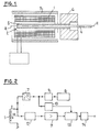
- FIG. 1 shows that the detector comprises a coil 1 whose length along the longitudinal axis A - A is practically equal to the magnitude of the measurement path traveled by the core 2 at the center of this coil.
- the coil 1 is protected from external electromagnetic influences by a shield 3.
- FIG. 1 shows that the core 2 is in two parts and that it comprises in its center a ferromagnetic rod 4 surrounded by a tube 5 with good electrical conductivity but of low magnetic permeability, eg a tube made of aluminum or copper or any other suitable material.
- the rod 4 can be made of iron or steel or any other suitable ferromagnetic material.
- the tube 5 with the rod 4 is linked by a support 6 to the external device (not shown) whose position must be measured.
- the detector operates by eddy currents, that is to say that the coil is supplied by an alternating current which creates by induction eddy currents in a thin layer on the outer surface of the conductive tube 5.
- the displacement of the core 2 in the coil 1 causes a variation in the impedance of the coil, due to the eddy current losses in this core.
- the temperature compensation is obtained by the particular constitution of the core, as follows.
- An increase in temperature causes a corresponding increase in the resistivity of the conductive tube 5. This increase in resistivity results in a decrease in the tube of the eddy currents which results in a decrease in sensitivity.
- an increase in temperature causes a corresponding increase in the magnetic permeability of the ferromagnetic rod 4, this increase in permeability resulting in an increase in the inductivity of the coil 1 and consequently in an increase in sensitivity. .
- the above shows that the Effects of temperature on core components are in opposite directions. It is therefore possible to obtain temperature compensation for the detector by an adequate choice of the materials of the core and the dimensions of the components. Practice has shown that the temperature drift can be reduced in a temperature range between - 40 ° C and + 250 ° C.
- the invention makes it possible to produce a position detector comprising only a single measuring coil whose axial length is practically equal to the measuring path, so that this detector is of simple construction, of low weight and size.
- the detector can operate between - 40 ° C and + 250 ° C without substantial temperature drift, which allows it to be used in an environment subject to both low and high temperatures. 'at high temperatures.
- the combination of core materials reduces the effects of temperature within the range indicated.
- Fig.2 shows a block diagram of an electronic circuit intended to process the voltage across the coil 1 by eliminating the resistive component of this voltage and creating an output signal depending only on the inductive component of the voltage .
- the coil 1 is supplied by a constant alternating current I delivered by a voltage / current converter 7 receiving the output signal from an oscillator 8, through a level adapter 9.
- the oscillator delivers for example a signal d a frequency of 10 kHz which is also the frequency of the current I.
- the adapter 9 delivers a reference signal to the converter 7 and to a phase shifter 10.
- the voltage V L at the terminals of the coil 1 is sent through a follower 12 to an amplifier 11.
- the output of the amplifier 11 is connected to the input of a demodulator 13 receiving the signal from the phase shifter 10.
- the output of the demodulator 13 is connected to a low-pass filter 14 which delivers a continuous output signal of value proportional to the position of the core 2 in the coil 1.
- the phase shifter 10 produces an output signal whose phase is offset by 90 ° to that of the reference signal, this phase shifted signal controlling the demodulator 13 so that the latter exclusively delivers a signal corresponding to the inductive component of the voltage V L at the terminals of the coil 1, this inductive component being phase shifted by 90 ° relative to the resistive component of this same voltage, itself in phase with the current I.
- This arrangement allows '' eliminate the influence of the variable temperature resistive component in the electronics output signal, resp. of the low-pass filter 14.
Landscapes
- Physics & Mathematics (AREA)
- General Physics & Mathematics (AREA)
- Measurement Of Length, Angles, Or The Like Using Electric Or Magnetic Means (AREA)
- Transmission And Conversion Of Sensor Element Output (AREA)
- Investigating Or Analyzing Materials By The Use Of Magnetic Means (AREA)
Applications Claiming Priority (2)
| Application Number | Priority Date | Filing Date | Title |
|---|---|---|---|
| CH4529/87 | 1987-11-20 | ||
| CH4529/87A CH674896A5 (de) | 1987-11-20 | 1987-11-20 |
Publications (3)
| Publication Number | Publication Date |
|---|---|
| EP0317497A2 true EP0317497A2 (de) | 1989-05-24 |
| EP0317497A3 EP0317497A3 (de) | 1991-01-30 |
| EP0317497B1 EP0317497B1 (de) | 1993-04-14 |
Family
ID=4277799
Family Applications (1)
| Application Number | Title | Priority Date | Filing Date |
|---|---|---|---|
| EP88810641A Expired - Lifetime EP0317497B1 (de) | 1987-11-20 | 1988-09-20 | Positionsgeber |
Country Status (4)
| Country | Link |
|---|---|
| US (1) | US5003258A (de) |
| EP (1) | EP0317497B1 (de) |
| CH (1) | CH674896A5 (de) |
| DE (1) | DE3880268T2 (de) |
Cited By (6)
| Publication number | Priority date | Publication date | Assignee | Title |
|---|---|---|---|---|
| FR2664045A1 (fr) * | 1990-06-27 | 1992-01-03 | Bosch Gmbh Robert | Detecteur de course, avec une bobine de mesure dont le corps est un materiau ferromagnetique. |
| EP0466604A1 (de) * | 1990-07-13 | 1992-01-15 | Societe D'applications Generales D'electricite Et De Mecanique Sagem | Vorrichtung zur Messung der relativen Lage von 2 zueinander beweglichen Teilen, die durch wenigstens einen teleskopischen Stossdämpfer verbunden sind |
| WO1996021841A1 (de) * | 1995-01-14 | 1996-07-18 | Robert Bosch Gmbh | Weggeber |
| EP1063496A1 (de) * | 1999-06-23 | 2000-12-27 | Peugeot Citroen Automobiles SA | Magnetischer Verschiebungssensor |
| FR2795502A1 (fr) * | 1999-06-23 | 2000-12-29 | Peugeot Citroen Automobiles Sa | Capteur de deplacement comportant une cible magnetique et un transducteur magnetique, destine notamment a un vehicule automobile |
| CN104534974A (zh) * | 2015-01-28 | 2015-04-22 | 长沙亿拓土木工程监测仪器有限公司 | 一种大量程电感调频式位移测量装置及方法 |
Families Citing this family (10)
| Publication number | Priority date | Publication date | Assignee | Title |
|---|---|---|---|---|
| US5430342A (en) | 1993-04-27 | 1995-07-04 | Watson Industries, Inc. | Single bar type vibrating element angular rate sensor system |
| DE60217457T2 (de) * | 2001-06-29 | 2007-10-25 | Matsushita Electric Works, Ltd., Kadoma | Positionssensor |
| DE10216635B4 (de) | 2002-04-15 | 2008-03-13 | Siemens Ag | Bewegungsdetektor nach dem Ferrarisprinzip |
| AU2002333765A1 (en) * | 2002-08-30 | 2004-03-19 | Fev Motorentechnik Gmbh | Sensor assembly for detecting the movement of a controlling element, which has a short overall length and which is displaced back and forth by an actuator |
| EP1617181A4 (de) * | 2003-04-22 | 2013-10-30 | Panasonic Corp | Verschiebungsdetektionseinrichtung |
| DE102005014659A1 (de) * | 2005-03-31 | 2006-10-05 | Robert Bosch Gmbh | Verfahren und Vorrichtung zur berührungslosen Drehwinkelerfassung eines drehbaren Elements |
| US7598734B2 (en) * | 2005-05-12 | 2009-10-06 | Panasonic Electric Works Co., Ltd. | Position sensor with a shield member for improving linearity of impedance of the detection coil |
| JP4960767B2 (ja) * | 2007-05-25 | 2012-06-27 | パナソニック株式会社 | 変位センサ |
| US8674685B2 (en) * | 2009-07-17 | 2014-03-18 | Hamilton Sundstrand Corporation | Magnetic flux oil level sensor for use in aircraft lubrication systems |
| FR2972795B1 (fr) * | 2011-03-15 | 2013-10-11 | Crouzet Automatismes | Capteur inductif de proximite et procede de montage dudit capteur |
Family Cites Families (16)
| Publication number | Priority date | Publication date | Assignee | Title |
|---|---|---|---|---|
| US2141890A (en) * | 1935-07-26 | 1938-12-27 | Siemens Ag | Variable inductance device |
| US2332868A (en) * | 1939-09-30 | 1943-10-26 | Nowak Alfred | High frequency variable inductance |
| US2340609A (en) * | 1940-08-03 | 1944-02-01 | Kobe Inc | Apparatus for determining displacements |
| GB1092362A (en) * | 1963-05-23 | 1967-11-22 | David Theodore Nelson Williams | Improvements in detectors for electrically conductive or magnetic particles |
| CH509573A (de) * | 1969-06-06 | 1971-06-30 | Vibro Meter Ag | Wechselstrom-Messanordnung mit einem Weggeber |
| US3891918A (en) * | 1971-03-23 | 1975-06-24 | James F Ellis | Linear displacement transducer utilizing an oscillator whose average period varies as a linear function of the displacement |
| GB1558206A (en) * | 1977-11-02 | 1979-12-19 | Tioxide Group Ltd | Position indicator |
| US4406999A (en) * | 1980-04-07 | 1983-09-27 | Clarostat Mfg. Co., Inc. | Inductive sensor |
| GB2074736B (en) * | 1980-04-26 | 1984-03-07 | Lucas Industries Ltd | Displacement measuring transducers and their use for sensing vehicle suspension displacements |
| DE3109930A1 (de) * | 1981-03-14 | 1982-09-23 | Robert Bosch Gmbh, 7000 Stuttgart | Weggeber |
| JPS6013405U (ja) * | 1983-07-05 | 1985-01-29 | 株式会社 東京衡機製造所 | アクチユエ−タ |
| US4717874A (en) * | 1984-02-10 | 1988-01-05 | Kabushiki Kaisha Sg | Reluctance type linear position detection device |
| FR2563368B1 (fr) * | 1984-04-20 | 1987-06-19 | Jeumont Schneider | Procede de compensation thermique d'un circuit magnetique |
| FR2565695B1 (fr) * | 1984-06-08 | 1986-09-26 | Europ Propulsion | Procede et dispositif de mesure de la composante reactive d'une impedance complexe |
| US4667158A (en) * | 1985-04-01 | 1987-05-19 | Redlich Robert W | Linear position transducer and signal processor |
| US4857824A (en) * | 1987-07-16 | 1989-08-15 | Cadillac Gage Textron Inc. | Movable core position transducer |
-
1987
- 1987-11-20 CH CH4529/87A patent/CH674896A5/fr not_active IP Right Cessation
-
1988
- 1988-09-20 EP EP88810641A patent/EP0317497B1/de not_active Expired - Lifetime
- 1988-09-20 DE DE88810641T patent/DE3880268T2/de not_active Expired - Fee Related
- 1988-09-23 US US07/248,352 patent/US5003258A/en not_active Expired - Lifetime
Cited By (8)
| Publication number | Priority date | Publication date | Assignee | Title |
|---|---|---|---|---|
| FR2664045A1 (fr) * | 1990-06-27 | 1992-01-03 | Bosch Gmbh Robert | Detecteur de course, avec une bobine de mesure dont le corps est un materiau ferromagnetique. |
| EP0466604A1 (de) * | 1990-07-13 | 1992-01-15 | Societe D'applications Generales D'electricite Et De Mecanique Sagem | Vorrichtung zur Messung der relativen Lage von 2 zueinander beweglichen Teilen, die durch wenigstens einen teleskopischen Stossdämpfer verbunden sind |
| FR2664538A1 (fr) * | 1990-07-13 | 1992-01-17 | Sagem | Dispositif de determination de la position relative de deux pieces montees mobiles l'une par rapport a l'autre, et reliees par au moins un amortisseur telescopique. |
| WO1996021841A1 (de) * | 1995-01-14 | 1996-07-18 | Robert Bosch Gmbh | Weggeber |
| EP1063496A1 (de) * | 1999-06-23 | 2000-12-27 | Peugeot Citroen Automobiles SA | Magnetischer Verschiebungssensor |
| FR2795502A1 (fr) * | 1999-06-23 | 2000-12-29 | Peugeot Citroen Automobiles Sa | Capteur de deplacement comportant une cible magnetique et un transducteur magnetique, destine notamment a un vehicule automobile |
| FR2795503A1 (fr) * | 1999-06-23 | 2000-12-29 | Peugeot Citroen Automobiles Sa | Capteur de deplacement comportant une cible magnetique et un transducteur magnetique, par exemple pour vehicule automobile |
| CN104534974A (zh) * | 2015-01-28 | 2015-04-22 | 长沙亿拓土木工程监测仪器有限公司 | 一种大量程电感调频式位移测量装置及方法 |
Also Published As
| Publication number | Publication date |
|---|---|
| EP0317497A3 (de) | 1991-01-30 |
| DE3880268D1 (de) | 1993-05-19 |
| CH674896A5 (de) | 1990-07-31 |
| US5003258A (en) | 1991-03-26 |
| EP0317497B1 (de) | 1993-04-14 |
| DE3880268T2 (de) | 1993-10-14 |
Similar Documents
| Publication | Publication Date | Title |
|---|---|---|
| EP0317497B1 (de) | Positionsgeber | |
| EP3814782B1 (de) | Stromsensor mit flux-gate | |
| WO2003014675A2 (fr) | Dispositif de detection | |
| EP0587491A1 (de) | Messanordnung mit Rogowski-Spule | |
| EP3555642B1 (de) | Stromsensor mit fluxgate | |
| EP1012609A1 (de) | Gerät mit bandpass grosser bandbreite zum messen electrischer stromstärke ineinem leiter | |
| EP0544576A1 (de) | Linear Servomotor mit veränderlicher Reluktanz | |
| WO2020002475A1 (fr) | Transformateur de mesure comportant un circuit imprime | |
| FR2692074A1 (fr) | Bobine de Rogowski. | |
| EP0401136B1 (de) | Detektionsverfahren und Einrichtung zum Temperaturkompensieren der Schwingung einer Resonanzschaltung | |
| FR2551864A1 (fr) | Appareil de mesure du niveau du metal fondu dans le moule d'une machine de coulee en continu | |
| EP2425212B1 (de) | Sensor und verfahren zur messung des oberflächenniveaus eines flüssigphasenmetalls | |
| FR2571845A1 (fr) | Systeme de mesure de distance inductif sans contact, notamment pour la detection du niveau d'un bain de metal liquide | |
| WO2020002484A1 (fr) | Circuit imprimé intégrant un pont diviseur de courant | |
| US4088027A (en) | Force balance servo accelerometer | |
| EP4127737B1 (de) | Schneller und spannungsdriftunempfindlicher rogowski-stromsensor | |
| JPH0743387A (ja) | 同軸シャント抵抗器 | |
| EP0492394B1 (de) | Gerät zur zerstörungsfreien Untersuchung mit Wirbelströmen mit Umschaltung zur Flussaddition-Flusssubtraktion | |
| FR2695479A1 (fr) | Capteur d'accélération. | |
| EP0151089B1 (de) | Vorrichtung zur Drehmoment- oder Torsionswinkelmessung | |
| FR2752059A1 (fr) | Dispositif de mesure d'un courant circulant dans un conducteur | |
| FR2624980A1 (fr) | Magnetometre vectoriel continu a capteur capacitif magnetostrictif et gradientmetre comportant application de ce capteur | |
| WO2000058976A1 (fr) | Procede pour la determination de la position d'un organe mobile dans au moins un entrefer principal d'un actionneur electromagnetique | |
| EP1020728B1 (de) | Anordnung zum messen eines Stromes in einer Leitung | |
| EP1063496B1 (de) | Magnetischer Verschiebungssensor |
Legal Events
| Date | Code | Title | Description |
|---|---|---|---|
| PUAI | Public reference made under article 153(3) epc to a published international application that has entered the european phase |
Free format text: ORIGINAL CODE: 0009012 |
|
| AK | Designated contracting states |
Kind code of ref document: A2 Designated state(s): DE FR GB IT |
|
| PUAL | Search report despatched |
Free format text: ORIGINAL CODE: 0009013 |
|
| AK | Designated contracting states |
Kind code of ref document: A3 Designated state(s): DE FR GB IT |
|
| 17P | Request for examination filed |
Effective date: 19901221 |
|
| 17Q | First examination report despatched |
Effective date: 19920226 |
|
| GRAA | (expected) grant |
Free format text: ORIGINAL CODE: 0009210 |
|
| ITF | It: translation for a ep patent filed | ||
| AK | Designated contracting states |
Kind code of ref document: B1 Designated state(s): DE FR GB IT |
|
| GBT | Gb: translation of ep patent filed (gb section 77(6)(a)/1977) |
Effective date: 19930414 |
|
| REF | Corresponds to: |
Ref document number: 3880268 Country of ref document: DE Date of ref document: 19930519 |
|
| PLBE | No opposition filed within time limit |
Free format text: ORIGINAL CODE: 0009261 |
|
| STAA | Information on the status of an ep patent application or granted ep patent |
Free format text: STATUS: NO OPPOSITION FILED WITHIN TIME LIMIT |
|
| 26N | No opposition filed | ||
| REG | Reference to a national code |
Ref country code: GB Ref legal event code: IF02 |
|
| PGFP | Annual fee paid to national office [announced via postgrant information from national office to epo] |
Ref country code: FR Payment date: 20050823 Year of fee payment: 18 |
|
| PGFP | Annual fee paid to national office [announced via postgrant information from national office to epo] |
Ref country code: GB Payment date: 20050912 Year of fee payment: 18 Ref country code: DE Payment date: 20050912 Year of fee payment: 18 |
|
| PGFP | Annual fee paid to national office [announced via postgrant information from national office to epo] |
Ref country code: IT Payment date: 20060930 Year of fee payment: 19 |
|
| PG25 | Lapsed in a contracting state [announced via postgrant information from national office to epo] |
Ref country code: DE Free format text: LAPSE BECAUSE OF NON-PAYMENT OF DUE FEES Effective date: 20070403 |
|
| GBPC | Gb: european patent ceased through non-payment of renewal fee |
Effective date: 20060920 |
|
| REG | Reference to a national code |
Ref country code: FR Ref legal event code: ST Effective date: 20070531 |
|
| PG25 | Lapsed in a contracting state [announced via postgrant information from national office to epo] |
Ref country code: GB Free format text: LAPSE BECAUSE OF NON-PAYMENT OF DUE FEES Effective date: 20060920 |
|
| PG25 | Lapsed in a contracting state [announced via postgrant information from national office to epo] |
Ref country code: FR Free format text: LAPSE BECAUSE OF NON-PAYMENT OF DUE FEES Effective date: 20061002 |
|
| PG25 | Lapsed in a contracting state [announced via postgrant information from national office to epo] |
Ref country code: IT Free format text: LAPSE BECAUSE OF NON-PAYMENT OF DUE FEES Effective date: 20070920 |